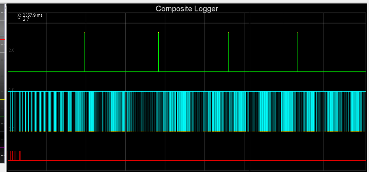
Part 2... catching up now.
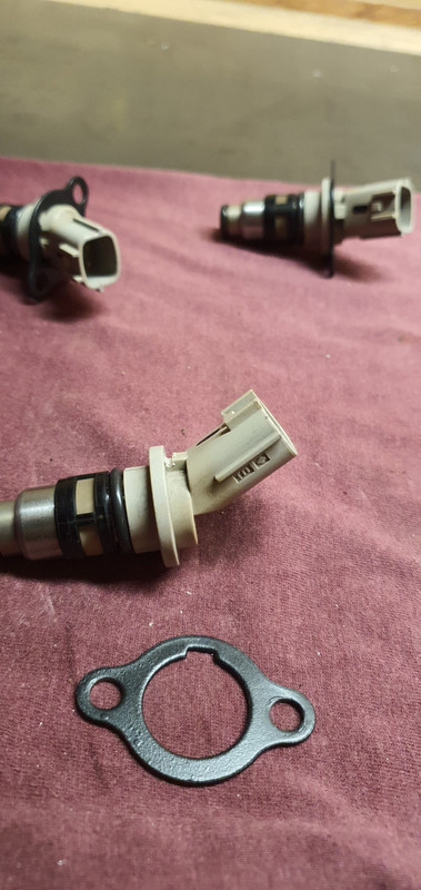
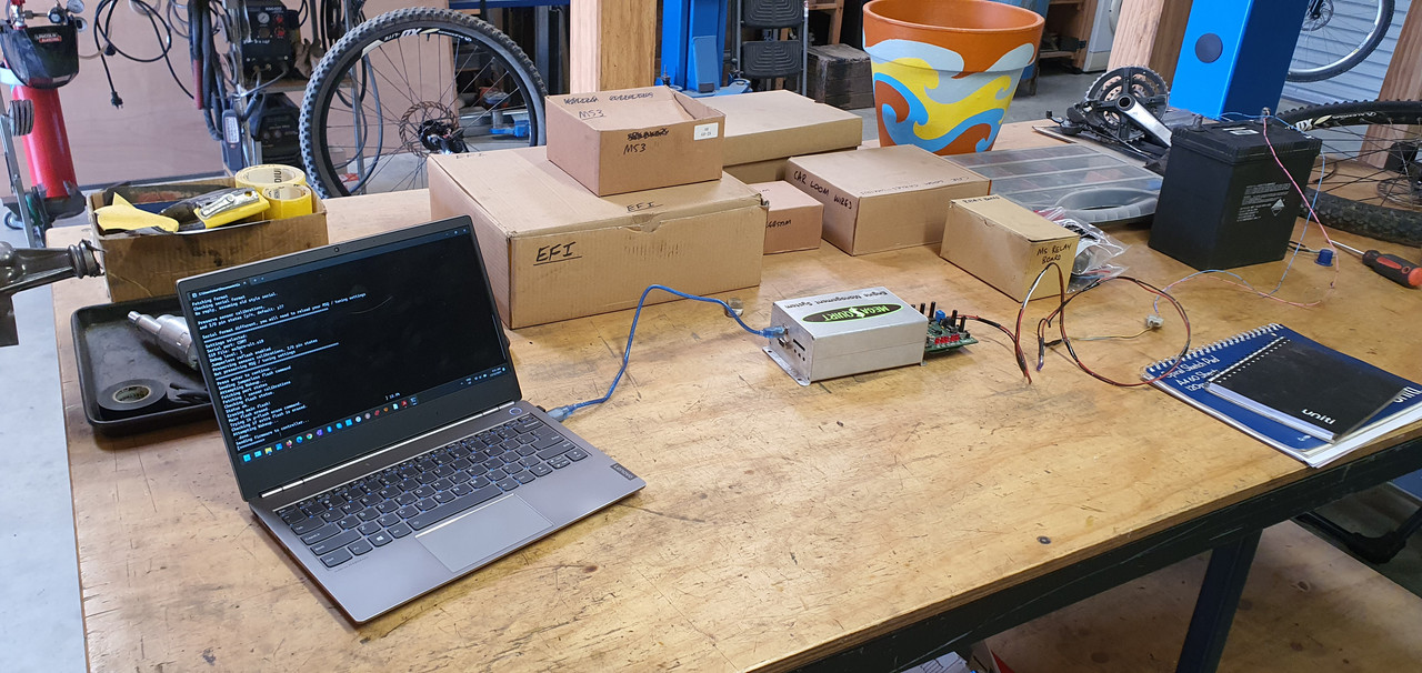
I finished what I needed to on the loom to enable testing of the injectors. I had made a simple little alloy jig that I could bolt the two rails onto and it sat high enough that 6 matching jam jars could sit below. We set this lot up on the big mobile steel bench and rolled it down to the front of the workshop near the entrance just in case it all goes a bit wrong. Set the ecu up along with a little 'ignition' switch and starter button for later testing of various engine sensors/ test running.
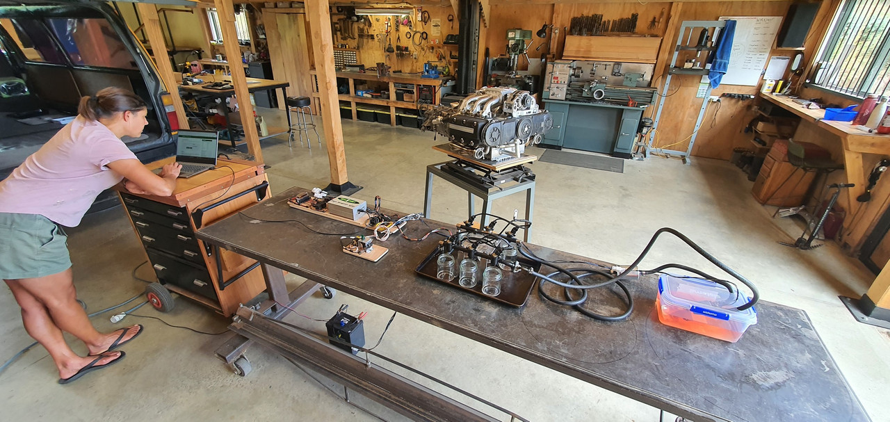
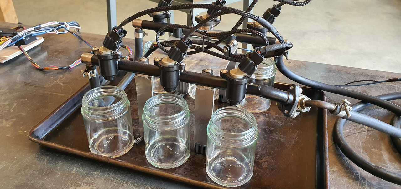
The tuning software that megasquirt uses, Tunerstudio, has a good set of testing programs built in including injector testing. Started using that and as soon as the injectors primed and started squirting we found a tiny leak.
Poos.
My home made rails were brazed together and there was one teeny bit the bronze hadn't flowed into leaving a tiny pin hole that let out a comical jet of fuel. Glad I tested them now.
Here under that lovely layer of carefully applied epoxy black...
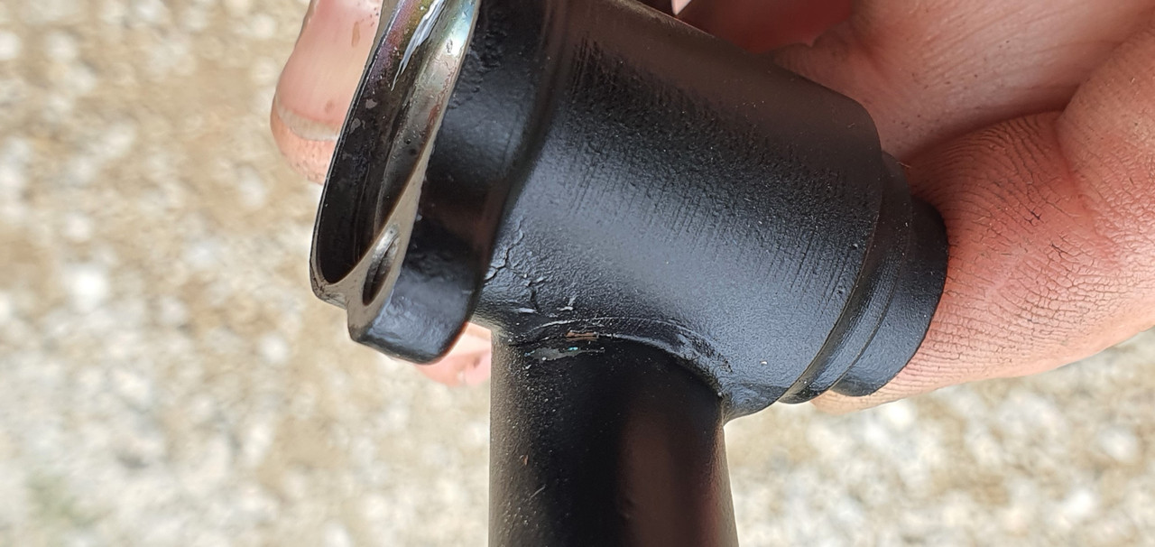
was a tiny hole..
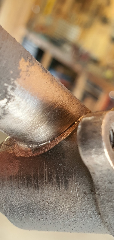
So out with the oxycet and I brazed it up.
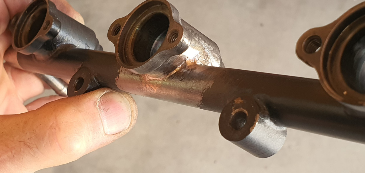
Then re-tested the setup. No more leaks

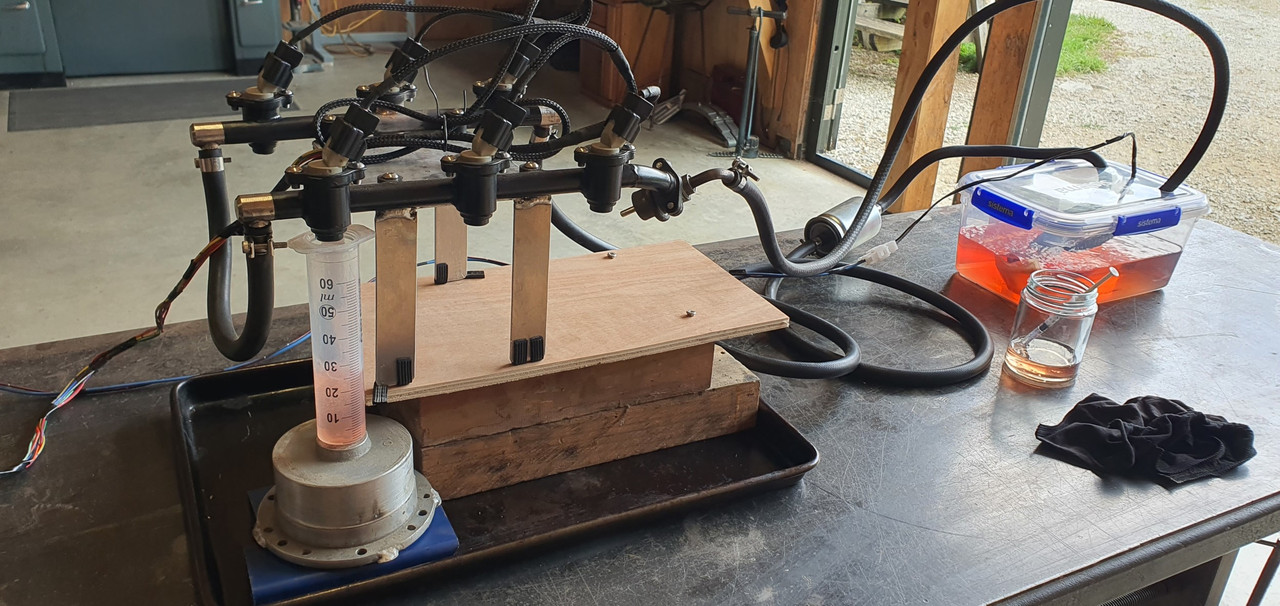
We ran through a few tests and made notes on fill rates at different opening times/frequencies etc etc to work out the injector dead times. Not a crucial thing to do but since it was setup as such it seemed rude not to. The battery I had was a bit tired and my charger couldn't keep up so I installed a larger Nissan charger at the front of the workshop. This also meant the testing was being done at a realistic voltage you'd expect to see.
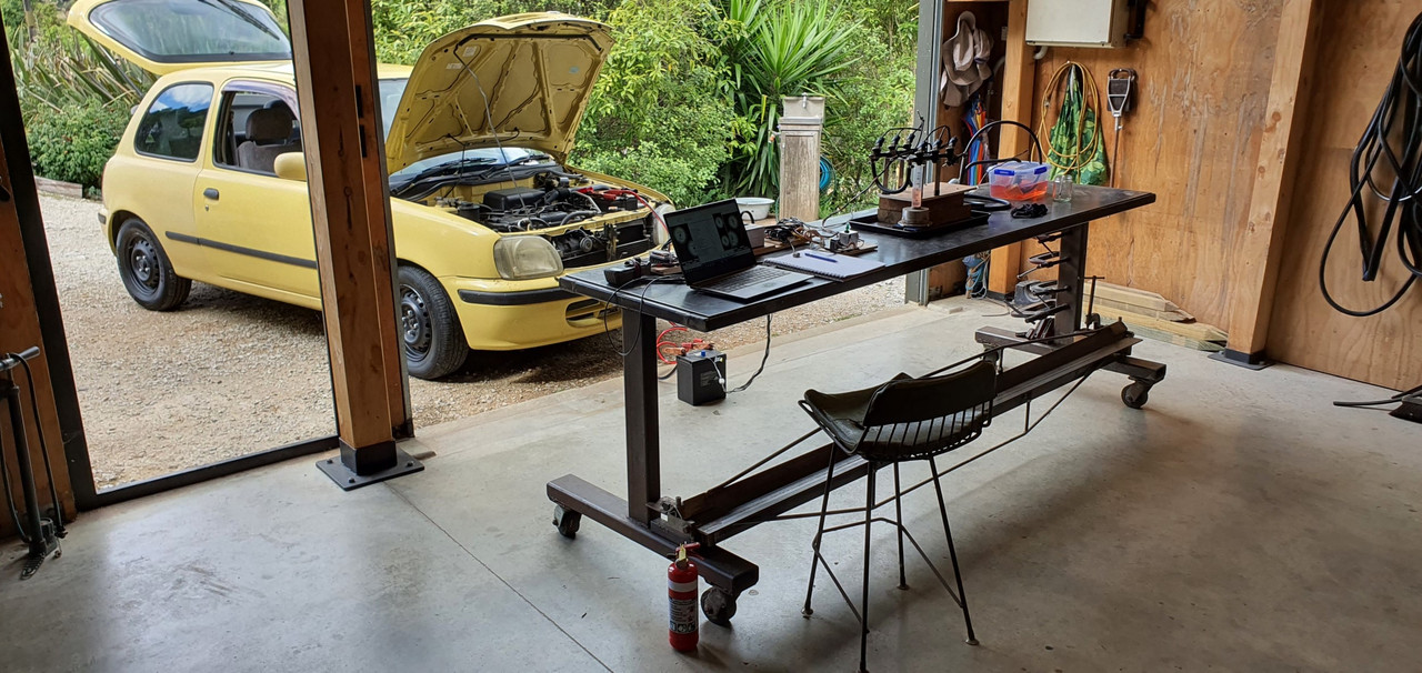
Happy the injectors were all matched and meeting the factory Nissan specs I packed all the stuff away.
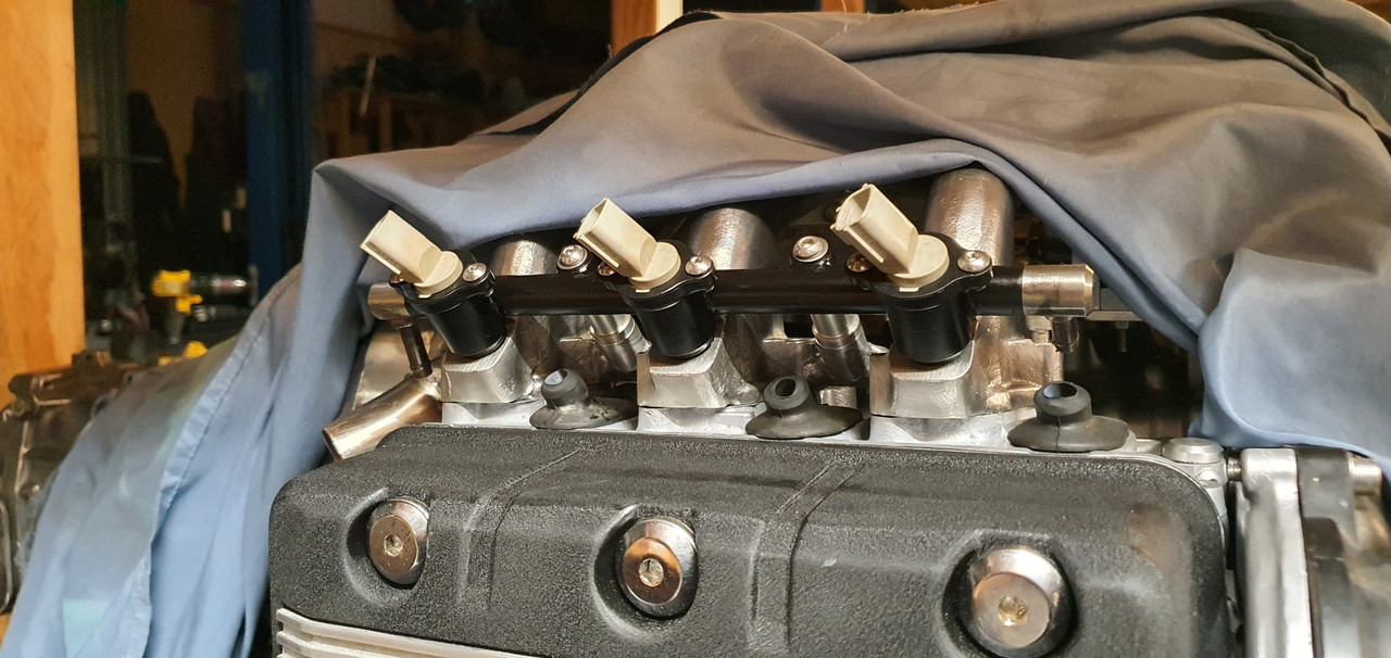
Then I fitted the inlet manifold gaskets and bolted the inlet in place on the engine, followed by the rails, with the repaired bit hand painted with epoxy as best I could to match.
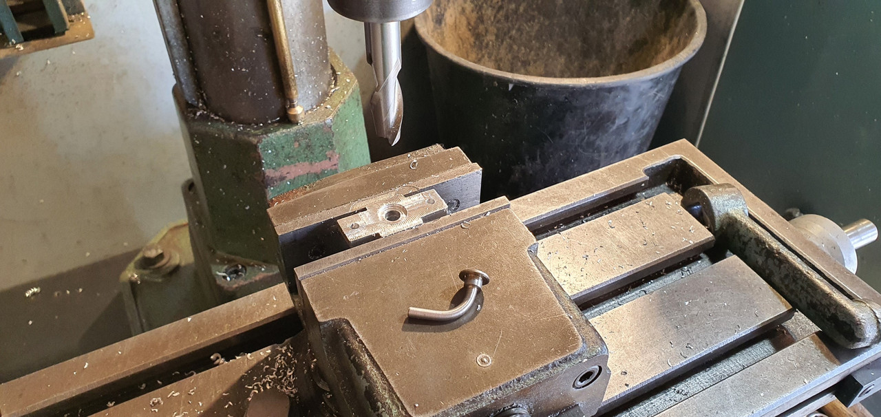
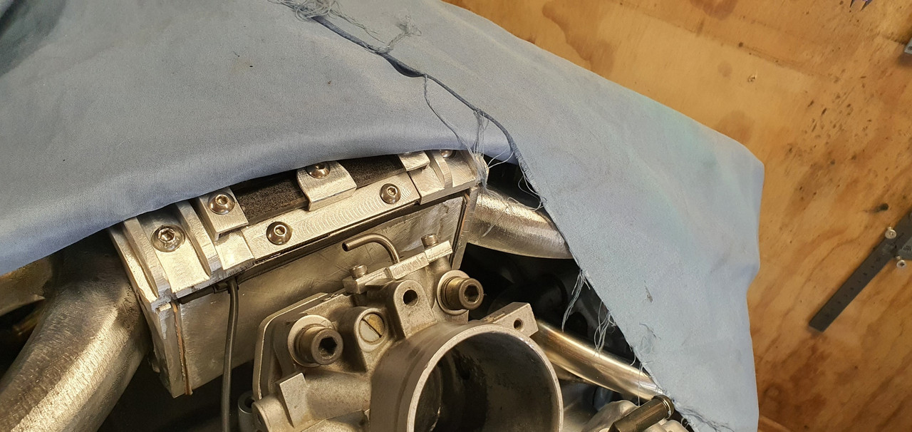
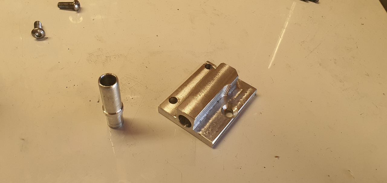
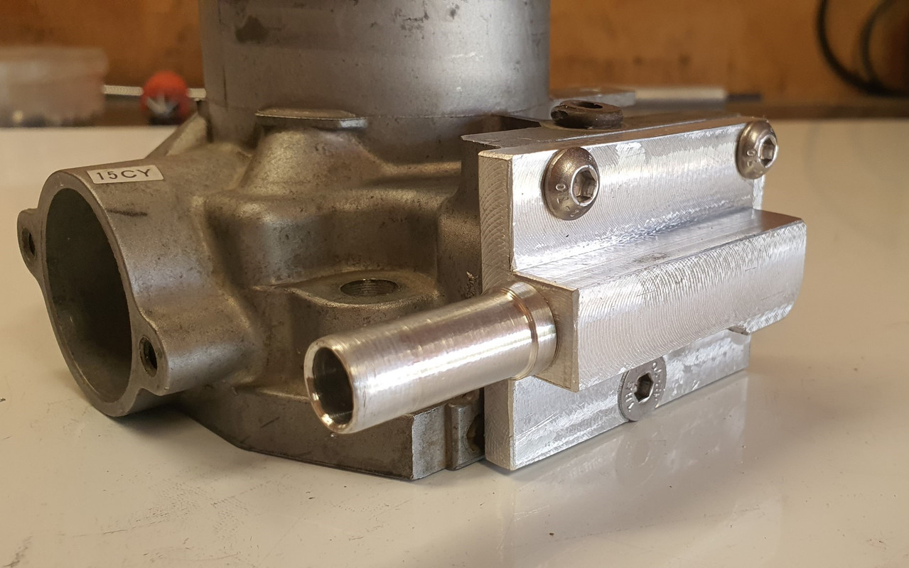
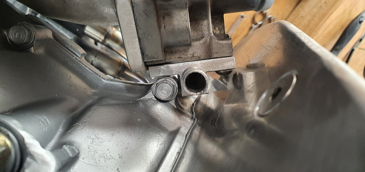
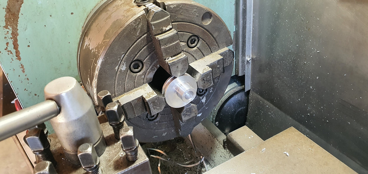
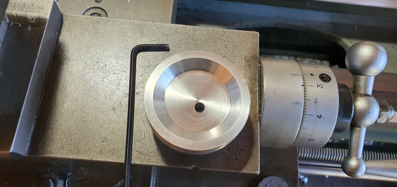
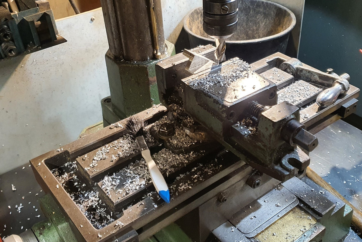
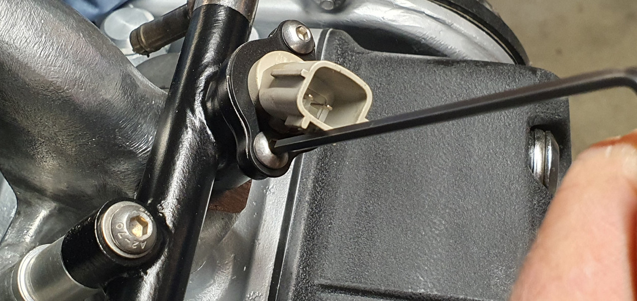
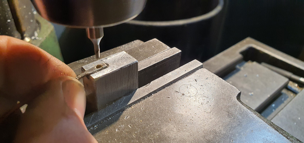
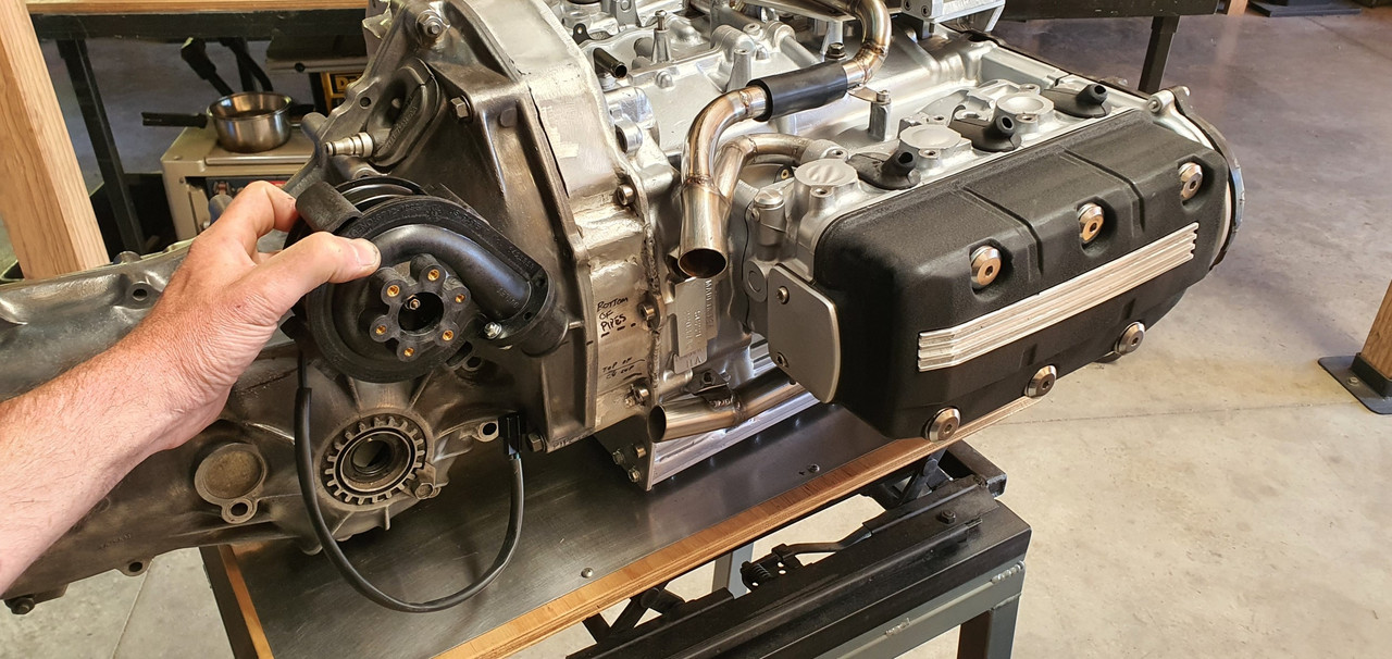
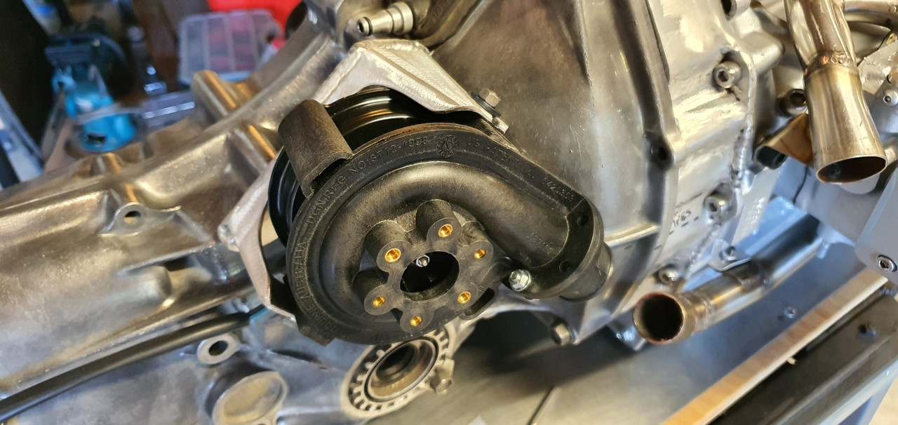
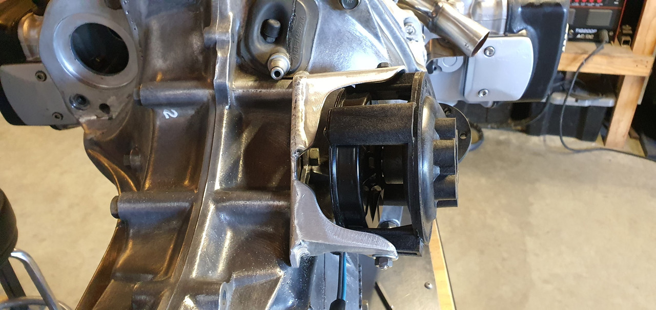
Next job to finish was the Bosch style idle air control valve. It had far too big in and out bosses so I machine up some stepdown parts to suit a more sensible sized tubing. I needed to mount it somewhere out of the way, safe and not on view because its not very pretty. I spotted a handy bracket on the bottom of the starter motor that has a threaded hole. Perfect! I made a little P clip to suit mounting the iacv.
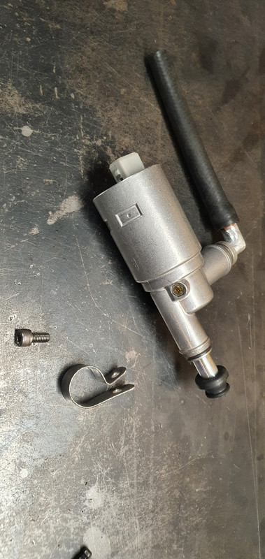
which bolts here..
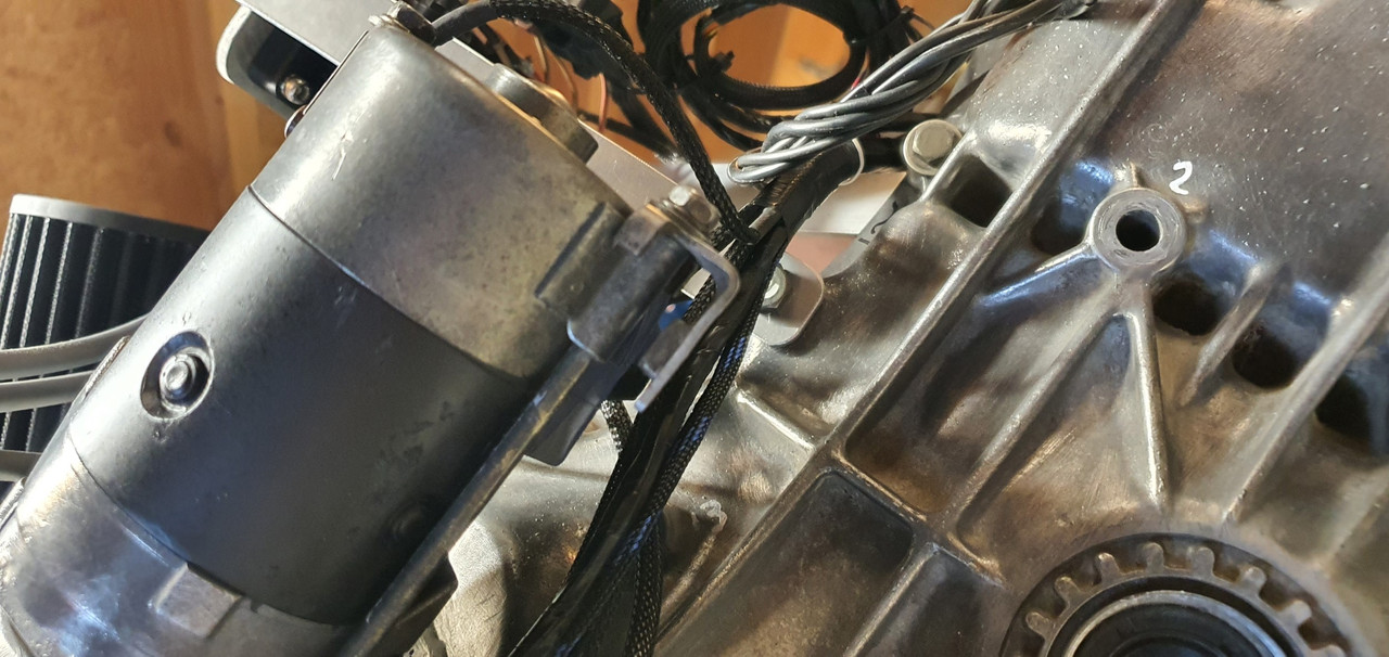
Like so...
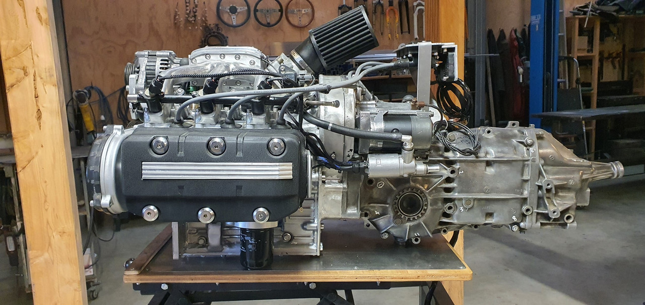
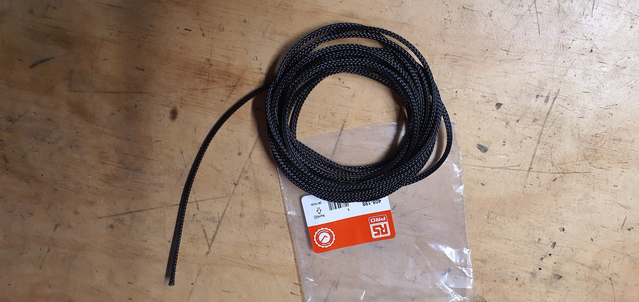
I did some more plumbing to suit and after a few last little bits of wiring the engine was about complete. I pod fitted the filter I'd bought a while back directly onto the throttle body but it will actually end up remotely mounted in a cooler spot. I was just waiting on some posh ventilation hose to arrive.
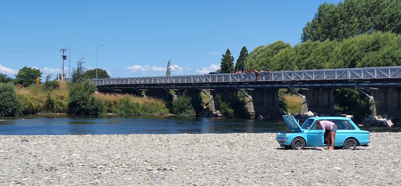
The Imp got a fresh wof and we took some pics of it when down at a local swimming spot near Motueka. It looked neat on the river stone so I took some pics..
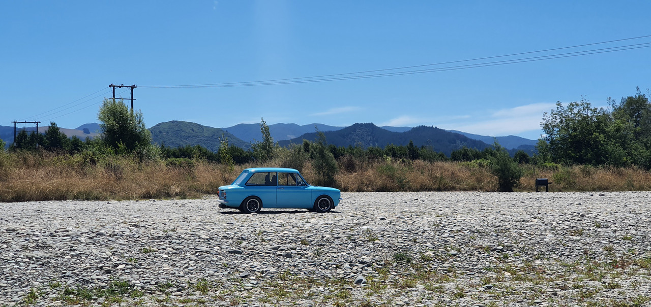
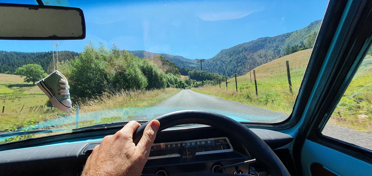
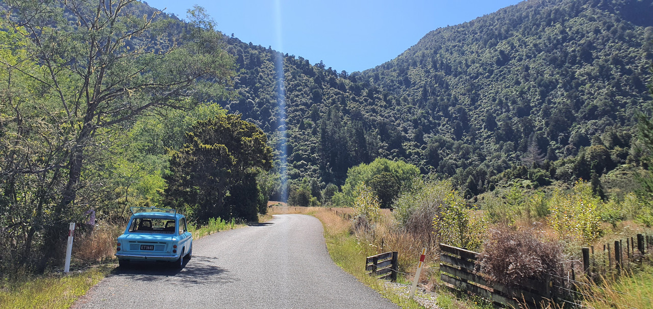
Went hooning up a local valley to get wild plums..
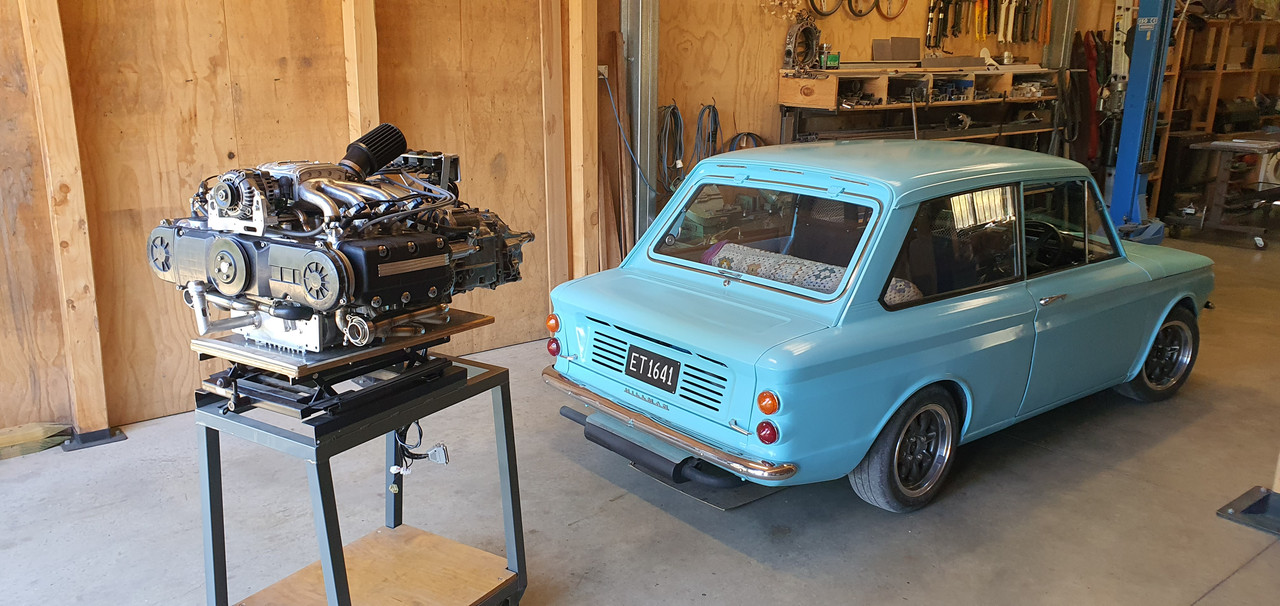
Got home and snapped some pics of the engine next to car. The perspective makes the engine look huge...
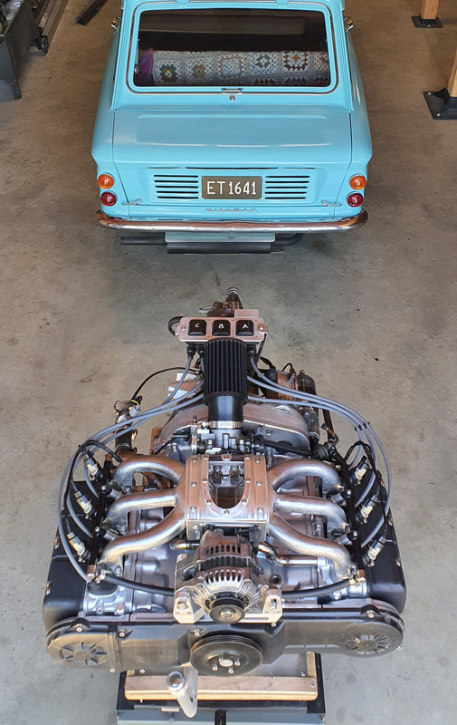
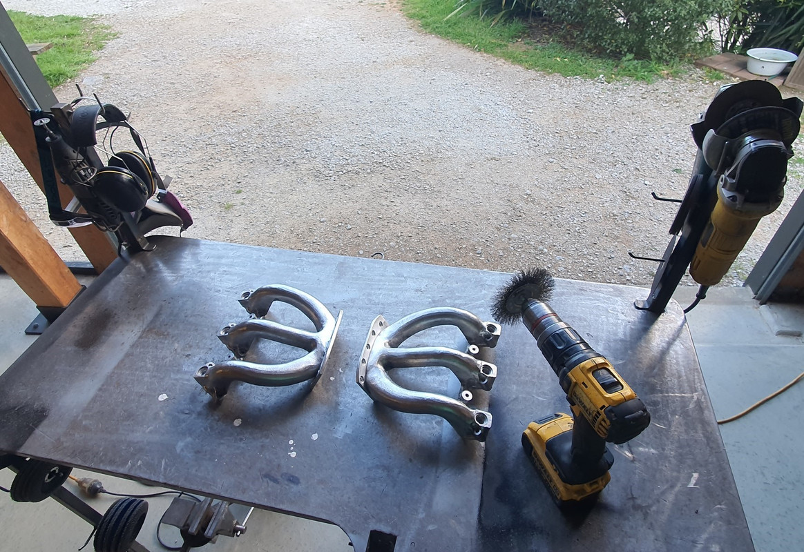
Next stage was to bolt the exhaust headers in place properly with the new gaskets and special nuts I'd bought.
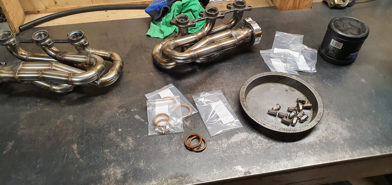
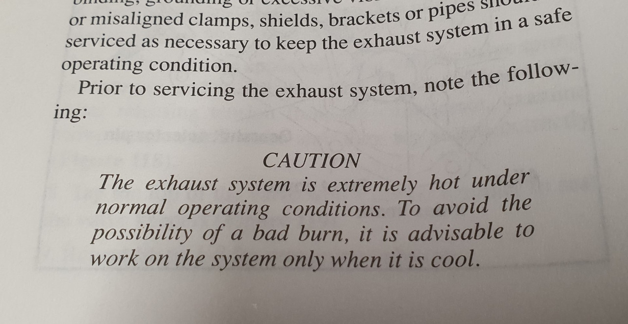
But before playing with exhausts always be aware of the potential dangers, as so carefully pointed out in the workshop manual !...
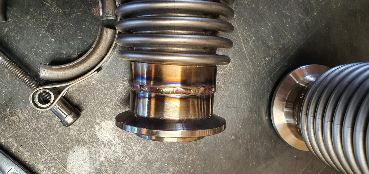
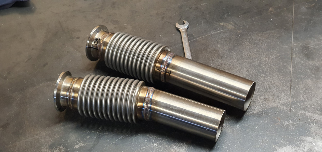
Manifolds bolted up fine but a few of the nuts are awkward to get started as its tight on space around the header pipes. Next parts in the exhaust chain was the flexible joints.
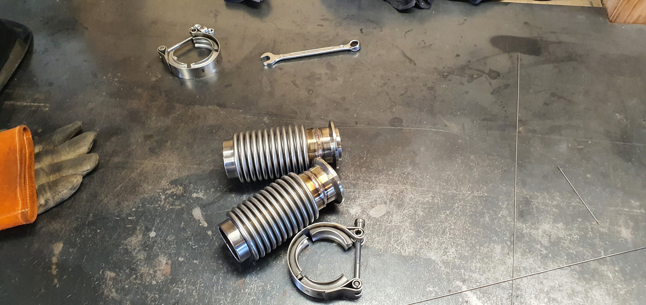
My welding was improved a bit by wearing some reading glasses.
I guess I just have to accept that aging thing and embrace the power of +1.5 because now I could actually see what I was welding. Its still not instagram weld porn but it'll do for this project
Bolted the cross member in place and with a bit of alloy I was able to check the heights to weld the next sections at.
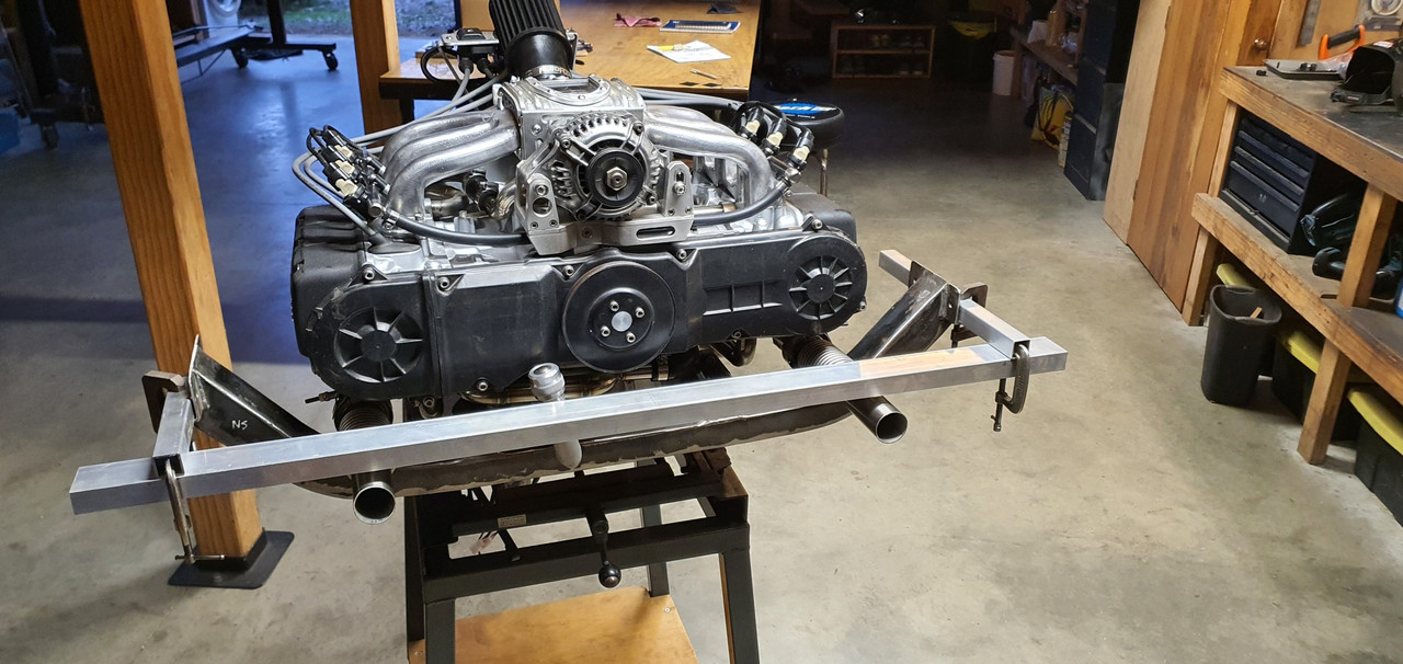
Unfortunately I must have fabricated the LH manifold out of line and I have ended up having to weld the secondary pipe at an angle to make sure the outlet heights match. It wont be easy to spot when its on the car, with a exhaust box hiding them. But I know its there...:doubt:
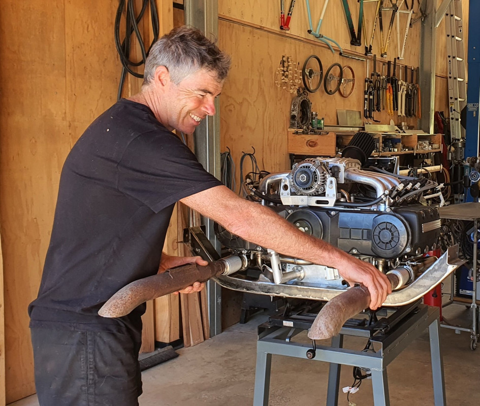
Or maybe I don't bother with a single large tranversely mounted silencer and just run a couple of old dumpy mufflers...
I was now at the point I could fill the engine with oil and test the oil system. Quite a while back I bought some quality oil when on sale..
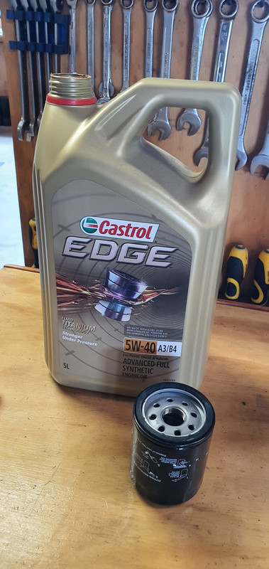
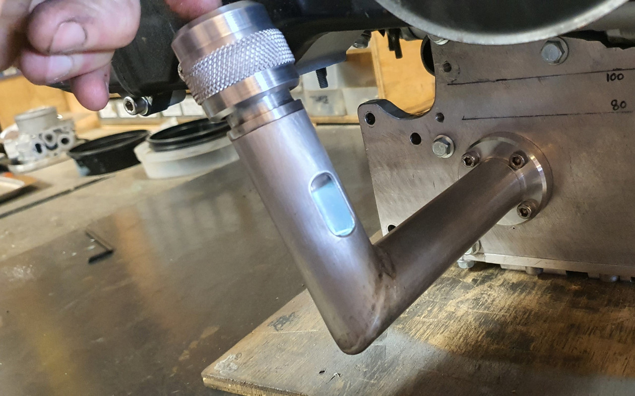
I filled the filter up first and then carefully filled the engine. Up until this point I had no real idea of exactly how much my resized sump would take before it got to height I wanted it at. I'd done some basic sketches and napkin formula and I knew it would be more than 3 litres. Hopefully more than 4. It almost took 5 litres to get to the halfway point on the sight glass and that will drop once the oil pump primed up and filled the oilways.
Cool. Great news then. I'm really happy it'll have a decent amount of oil in there.
Now remember back to around the end of December 2021 when I wrote this...
"Lastly I needed to bolt the sump cover in place. I had to think carefully about bolt placement for sealing purposes and get the bolts square. This sump plate is going to have to be sealed well because there is no usual high sided sump like most cars. Hence I built it rigid to help against flex. Good quality sealant will be the order of the day*
*It will leak. Its a British car. Its destined to leak."
Well then. Guess what. It leaked! Ha.
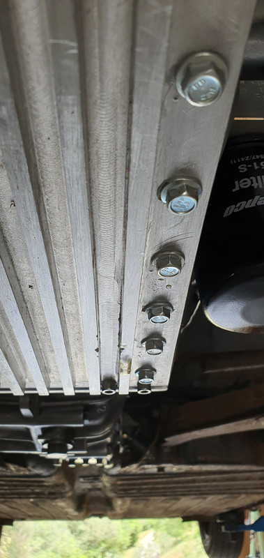
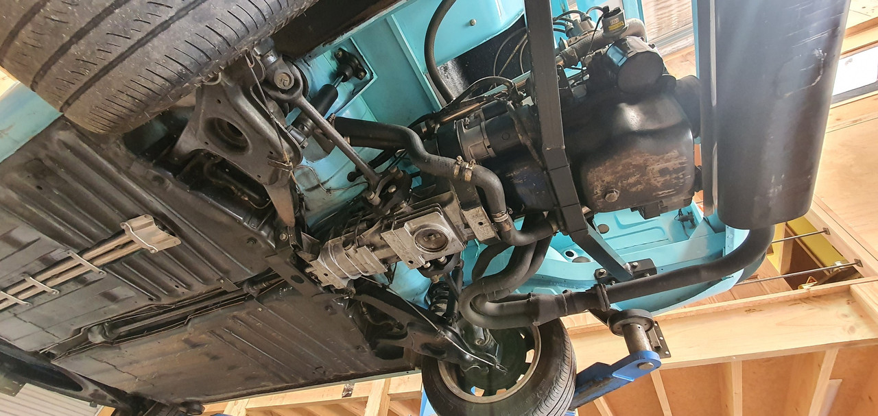
Just after patting myself on the back at having a great sump capacity the level started to drop and was leaving a good puddle on the engine stand top. So Hannah helped me move the engine so I could drain the sump and then I mounted the engine/box assembly into the spare imp. On a positive note I was chuffed with how quick and easy it was to bolt up in place by myself - all of about 5 or 10 minutes. Engine in place and with the car up in the air I took that above photo. I had a good idea where it was coming from and wasn't feeling to glum ( no even a single toy was even lifted from my cot)
I unbolted the sump plate and found the hole...
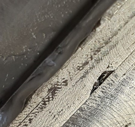
When I was making the sump plate and milling the slots in the plate it had shifted out of line without me spotting it had done so until too late. I had to weld up the resulting mess and re-machine that area. I thought it was fine but I'd missed a tiny pinhole, maybe exposed when I machined the inside of the plate out to take some weight off it.
The plate got a good clean (that threebond sealant is tenacious stuff! ) and I fixed the hole with a dollop of JB weld.
Took some pics of engine from below with its innards exposed..
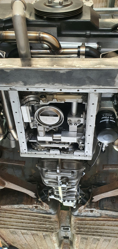
Little pistons...
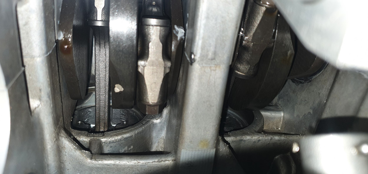
Bolted the sump plate back up, waited till the following day and refilled it. This time no puddles.
Yay.
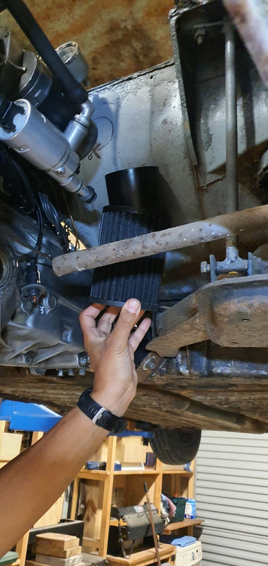
While the engine was bolted into the spare imp I took the chance to double check measurements and clearances. It was all looking good and I was very happy that I had placed things ideally, especially as most measurements were taken in awkward areas by all sorts of various ruler/tape measure/level balancing acts. The coils, just mounted on their makeshift bracket for bench testing, are actually almost bang on in the right place and only sitting a touch too high. The filter hose will just clear the underside of the parcel shelf and there's heaps of room for the remote filter..
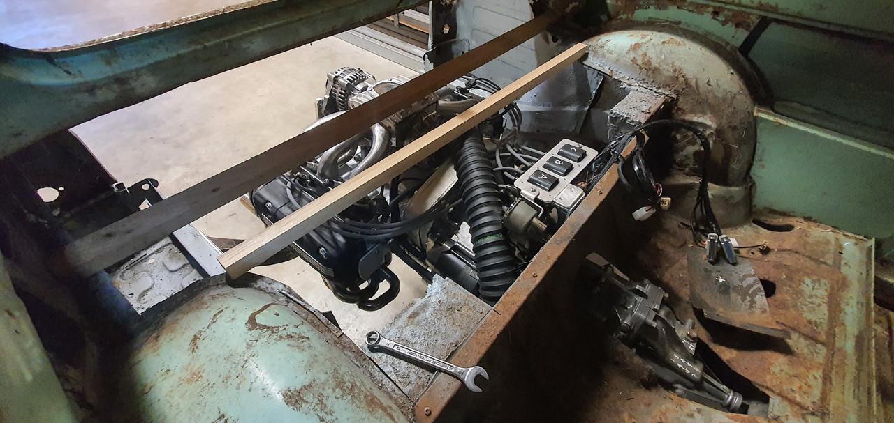
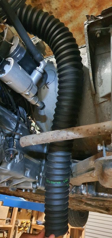
Hose (turned up the day before) ..
Hannah's hand holding filter roughly where it will be mounted to the bulkhead...
Lots of room out back between engine and where the removable rear valance bolts in place..
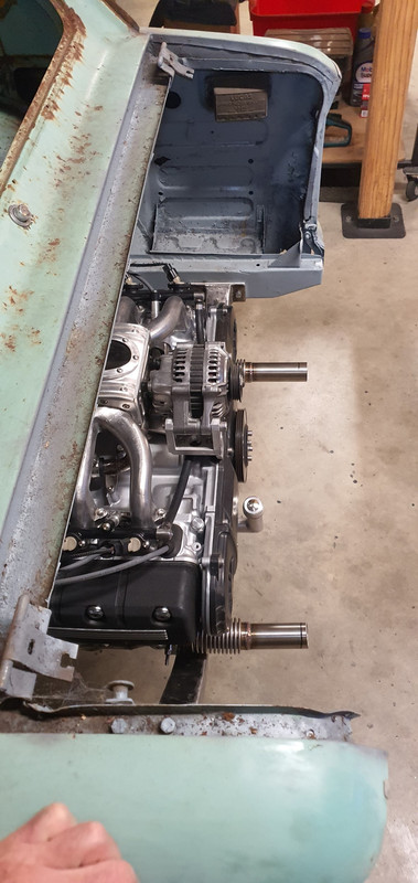
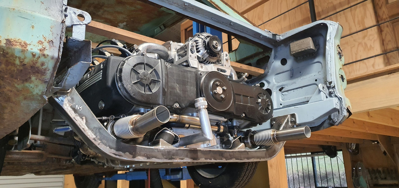
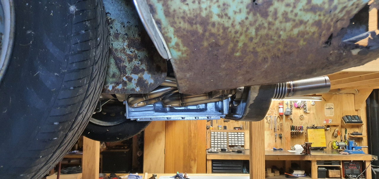
and lastly, the 'Mandalorian spaceship' will not at all be hidden by the rear parcel shelf ..
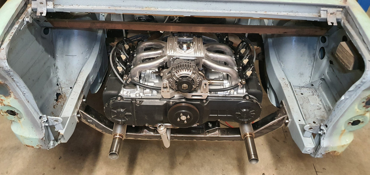
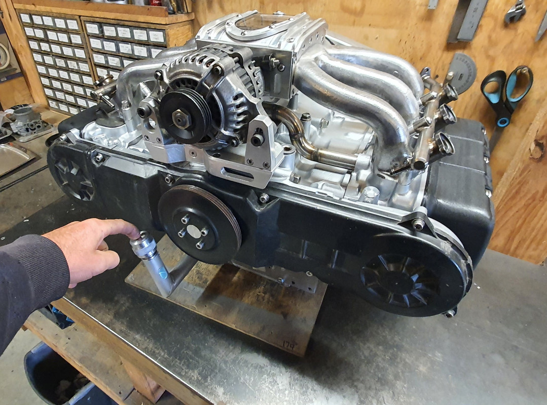
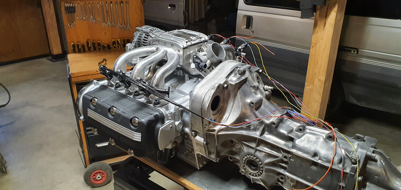
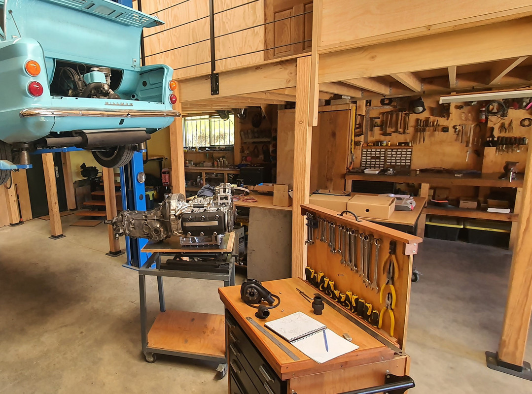
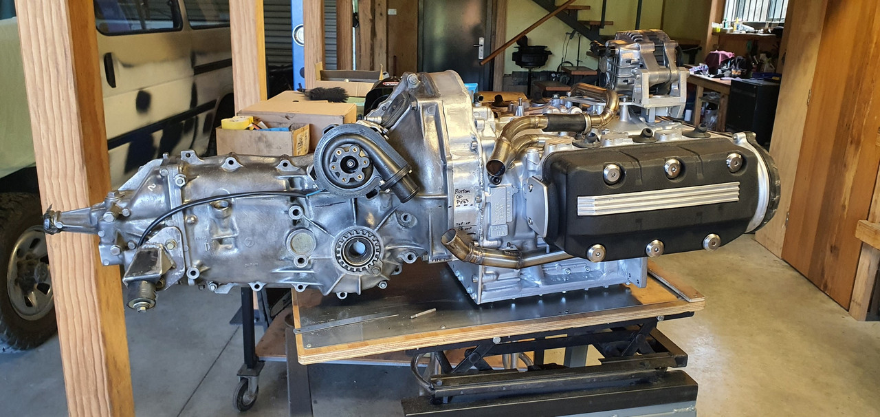
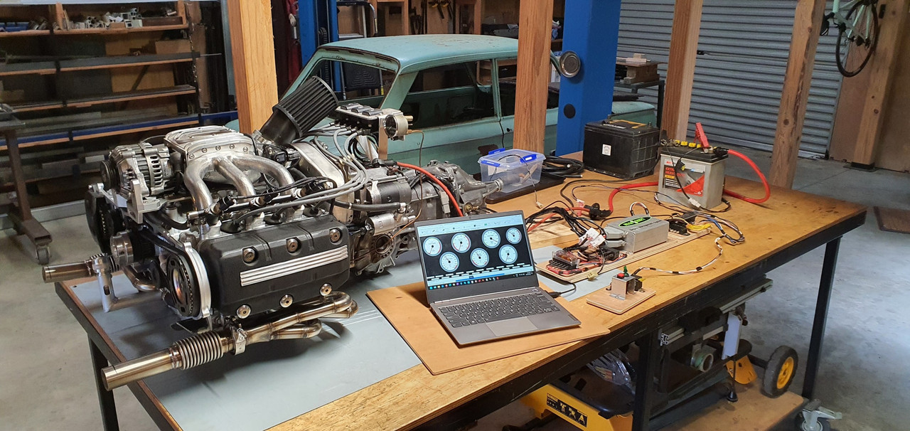
Engine is now out and back on the bench for more 'bench testing'...


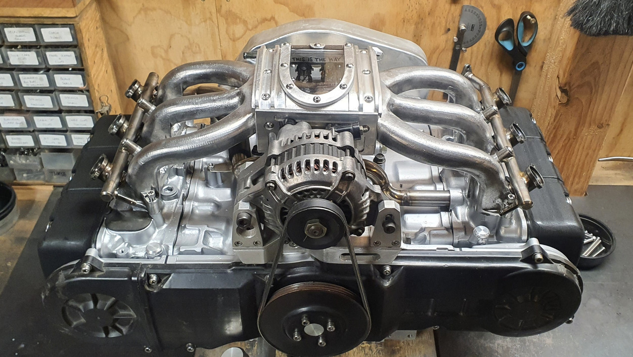
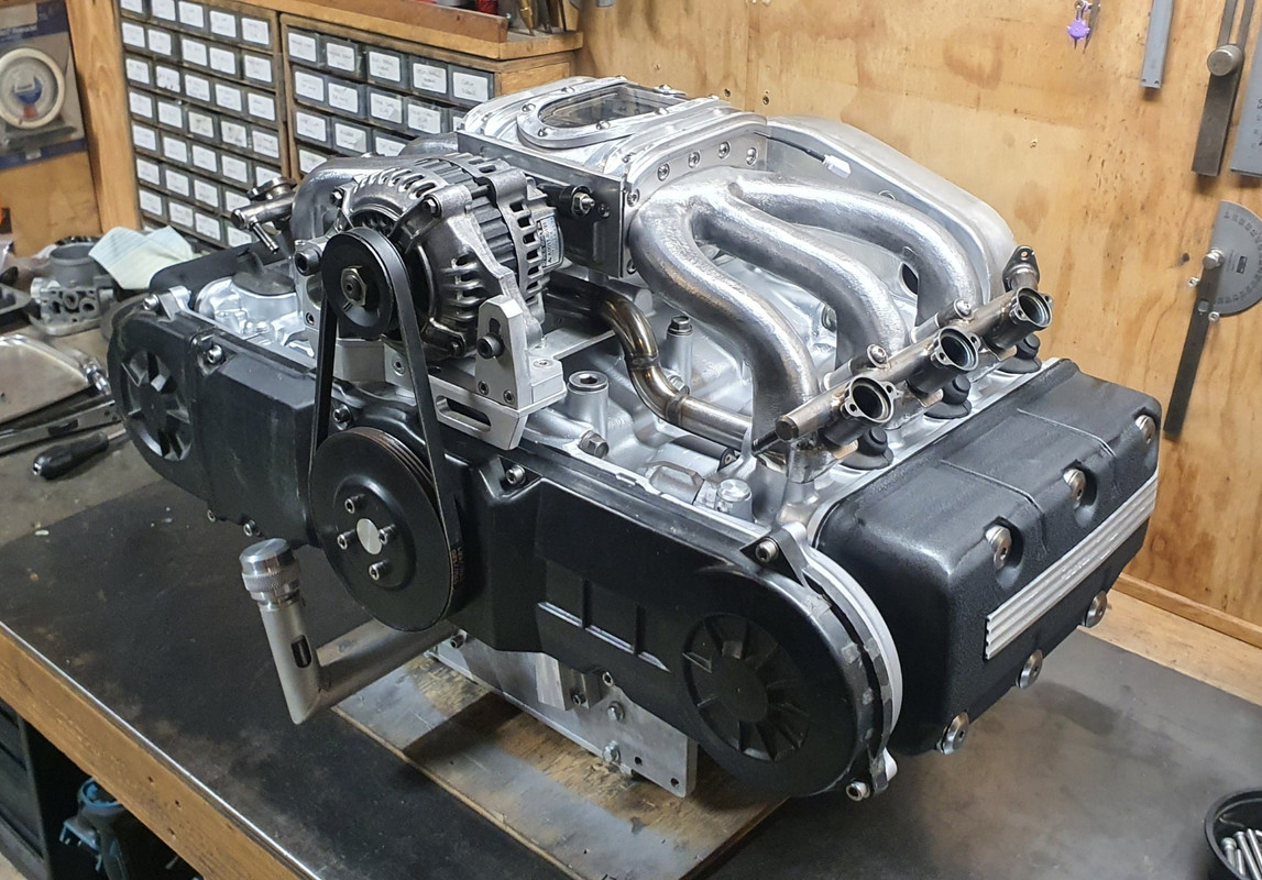
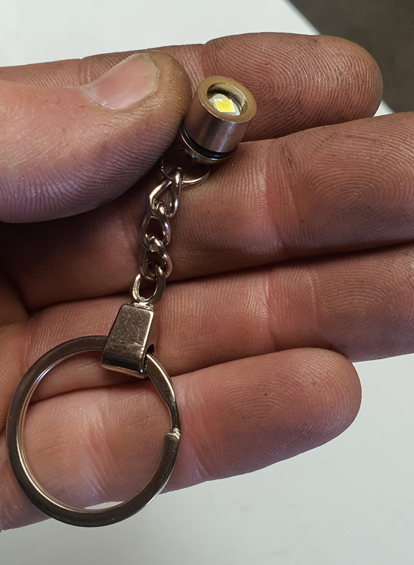

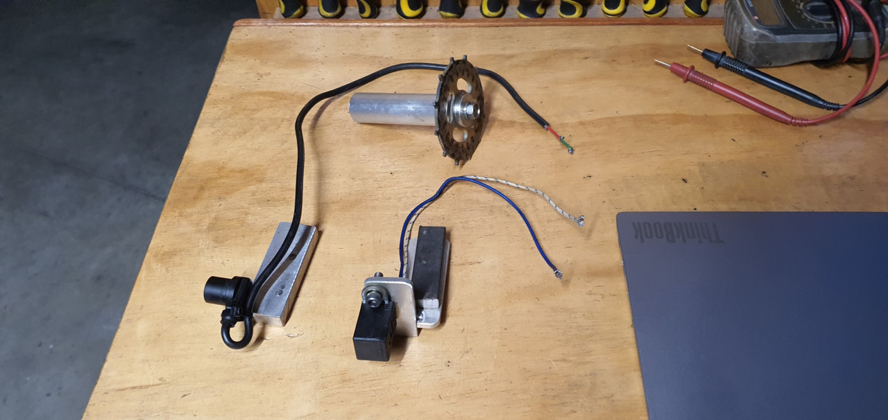
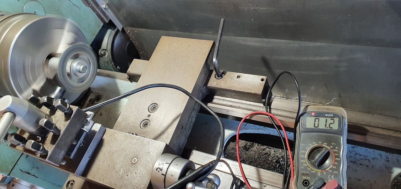
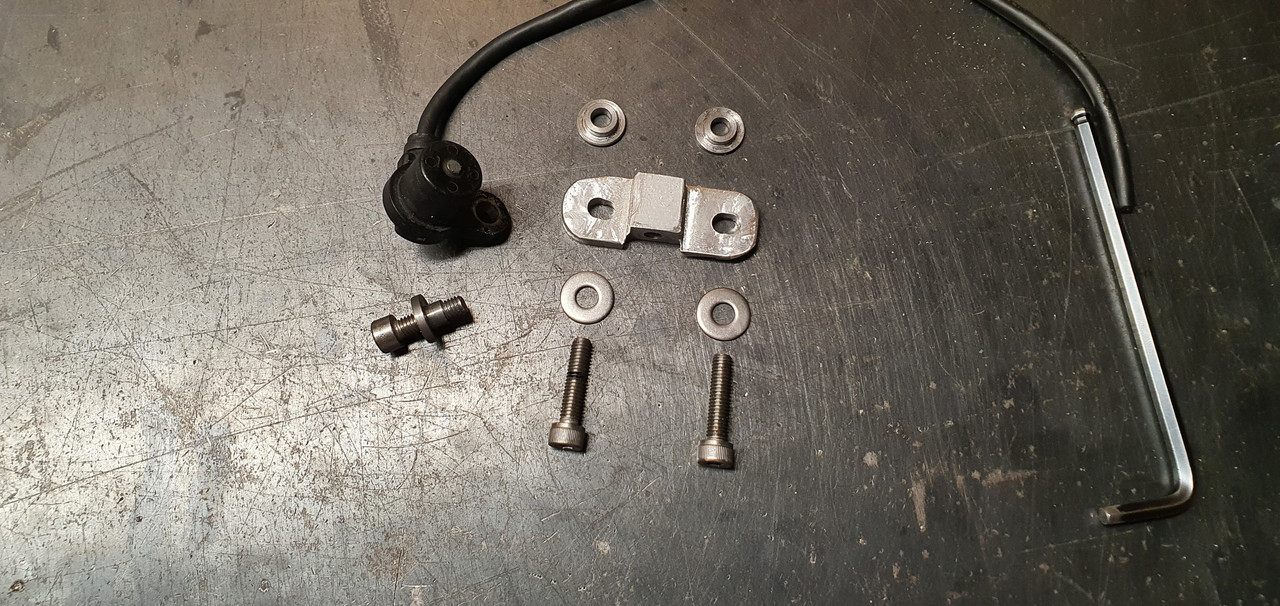
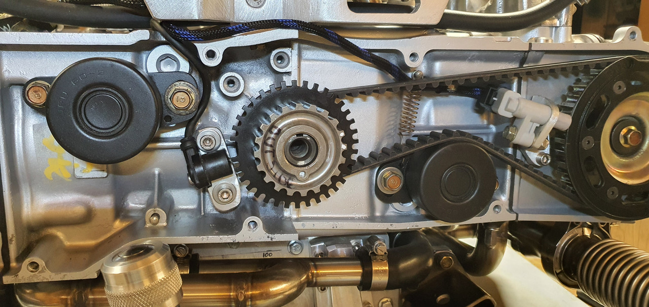
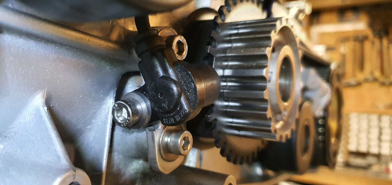
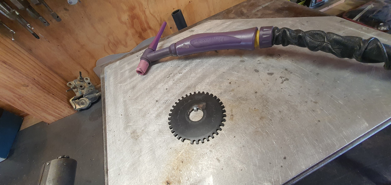
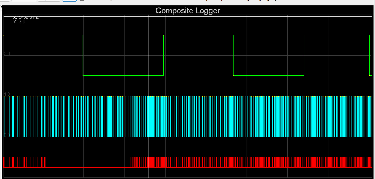
 I was tired so off to bed.