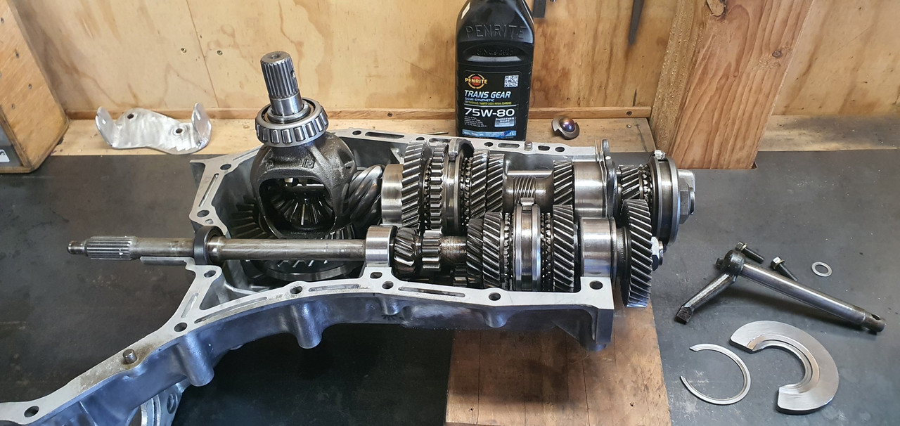
I glooped the two halves together, bolted them up, bolted the tailhousing on and let it set. Following morning it was bolted onto the engine, unsurprisingly a bit heftier with all the gubbins placed back within the box. Its about 9kg heavier than the standard imp box.
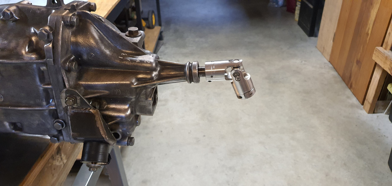
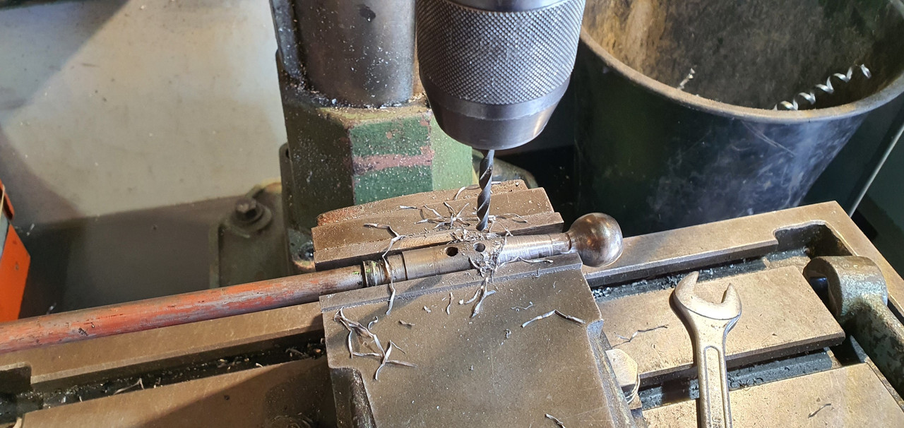
I then started to fit the first part of the gearshift linkage. The first of those snazzy universal joints, handily available in a diameter to suit the shifter shaft on the Subaru box. I just needed to add a small locating hole for the grub screw...
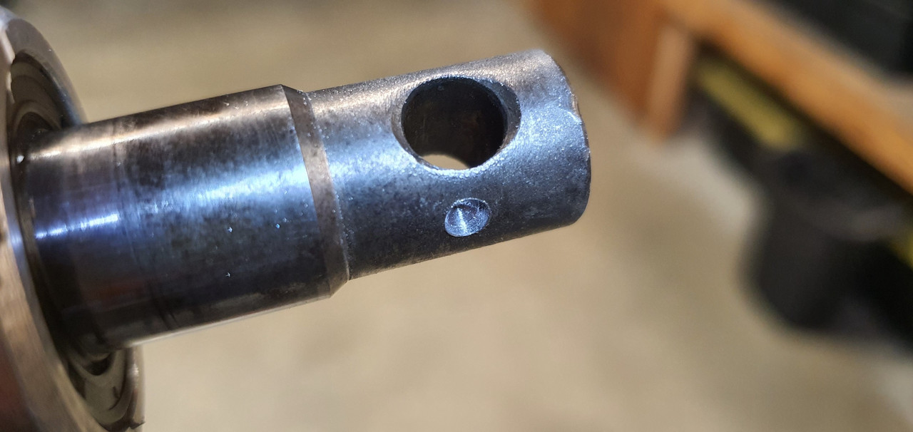
Universal in place..
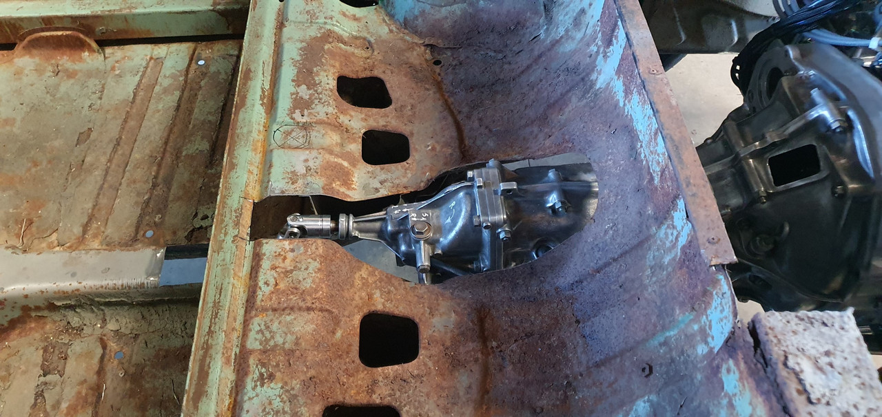
Engine and box were then bolted back into the car. This bit is so quick and easy when using the 'engine stand 2000'. It takes about 10 mins and I'm getting quicker. It'll be slower when there's shift linkage to undo and driveshafts to slip out of the way. But at least the main heavy awkward part is actually easy.
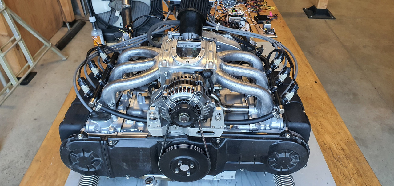
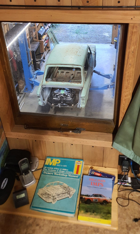
That lot in place I took some pics. Its neat to be able to look out from the one of the lounge room windows down onto the workshop floor and see this...
With that lot in place I was able to suss out the angles I could get away with, as shallow as possible and allowing for the handbrake mechanism.
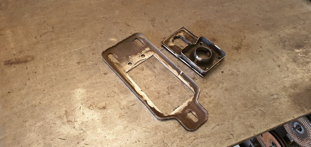
I had this old imp gearstick assembly that a fellow Imp friend kindly posted over to me. Some previous owner of the car he got it from liked painting things. Everything. Multiple times...
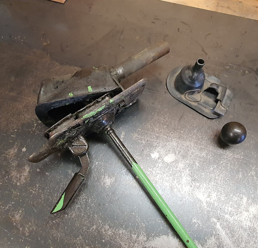
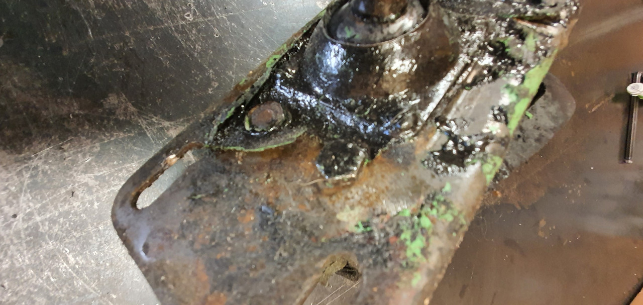
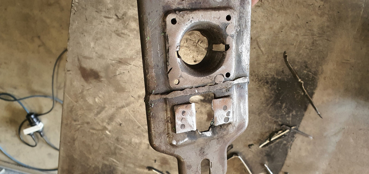
I scrapped all the layers off, took it apart and cleaned off the dirty old grease. Discovered it had been cobbled together from two old shifter bases. It was originally a very early Imp unit when the very first cars had an automatic choke, which often proved problematic. Hillman then changed the cars over to a manual choke with a nifty little lever in front of the shifter. This mount had been added to the early base. Which means they must have chopped up a later baseplate to get the choke mount. Why they didn't just fit the entire newer base plate I don't know. But what I had in front of me was a frankenstein of base plates with barry spec welding and fixes, but also including a not too badly made bronze bush on the lever where there is normally a (wornout) plastic bush.
I had a couple of shift rods to choose from. I chose the least worn.
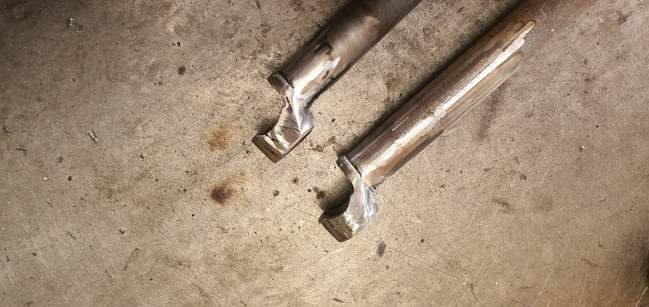
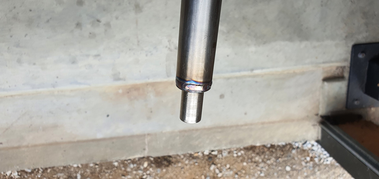
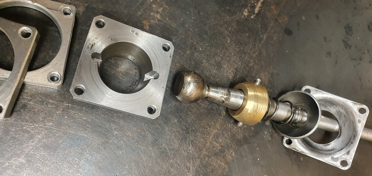
Moving back to the gearbox end I machined up some shaft ends from stainless bar to suit the universal joints. I had some stainless tube and welded the ends in place on the first shaft that runs from the gearbox universal down to the tunnel.
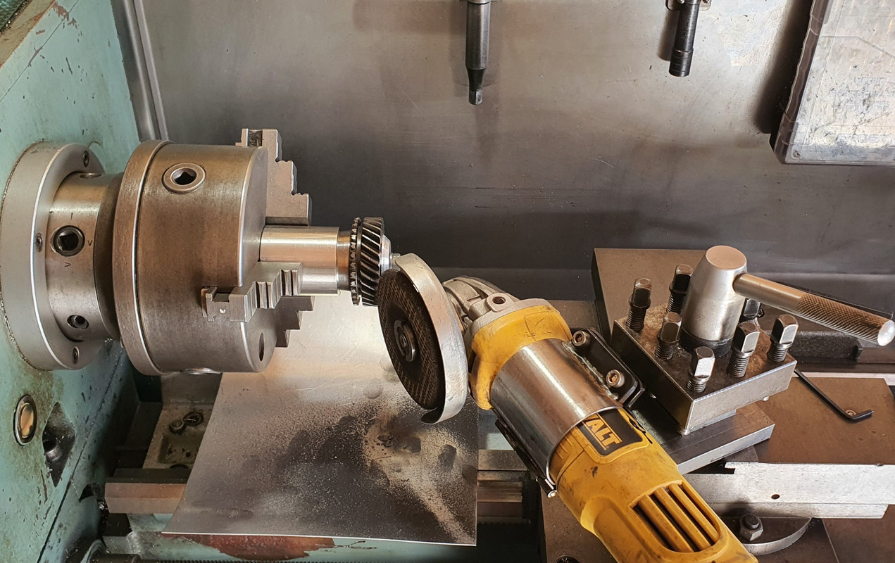
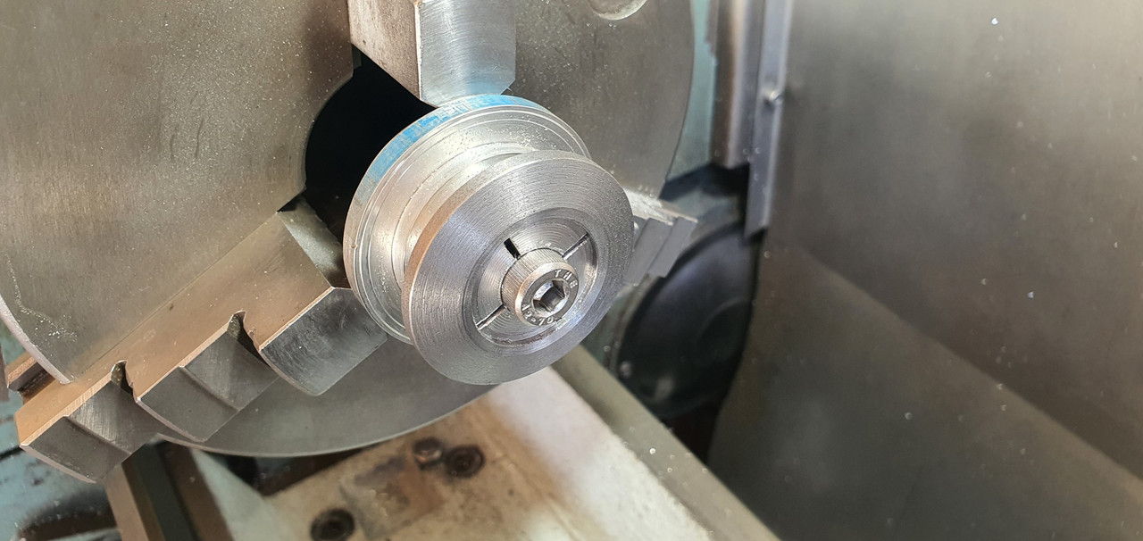
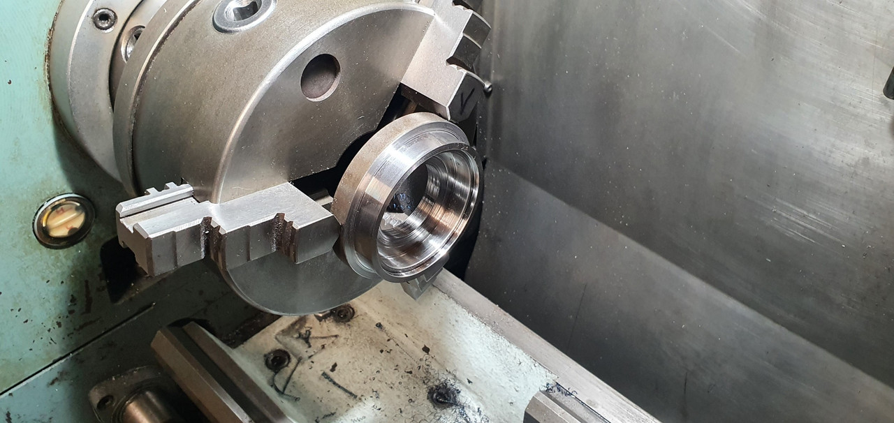
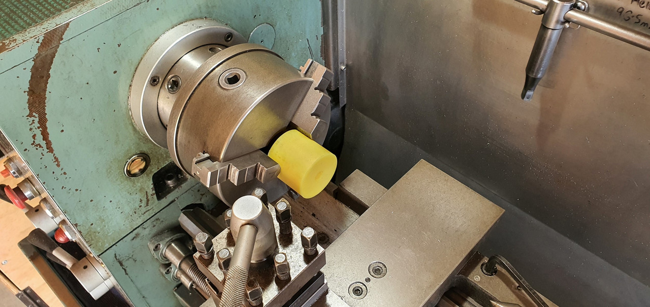
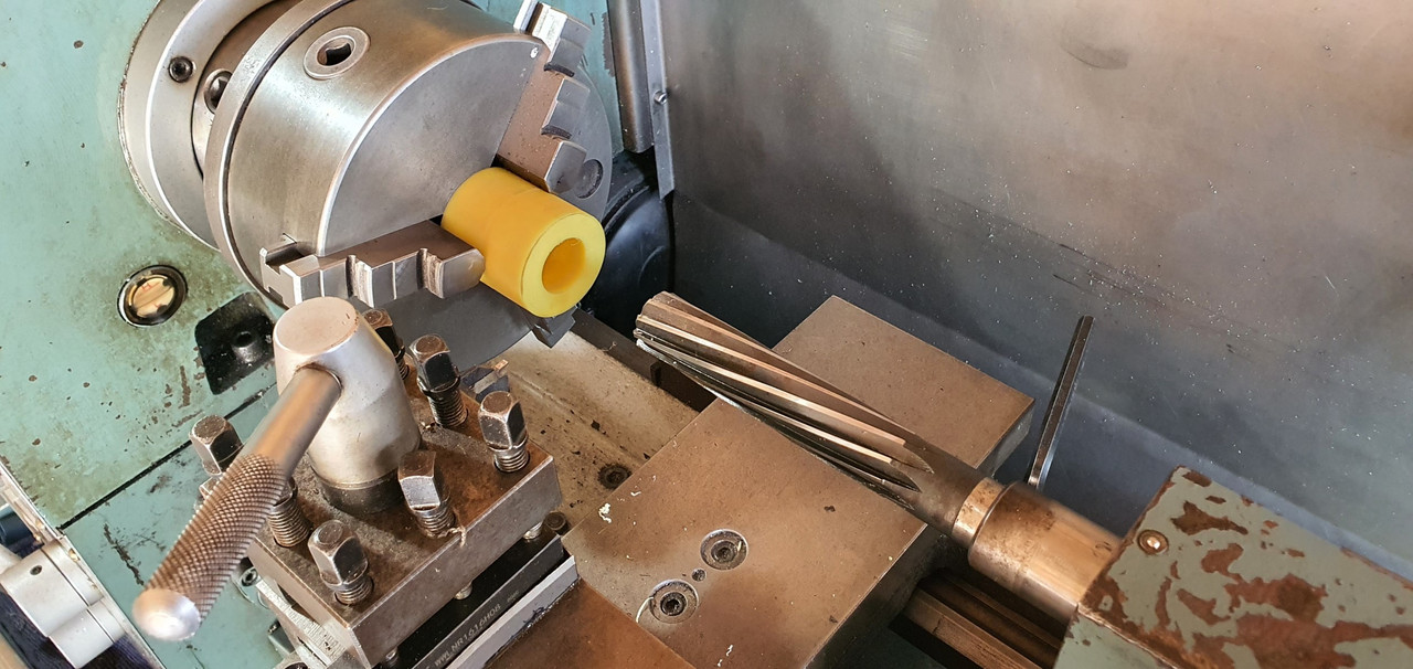
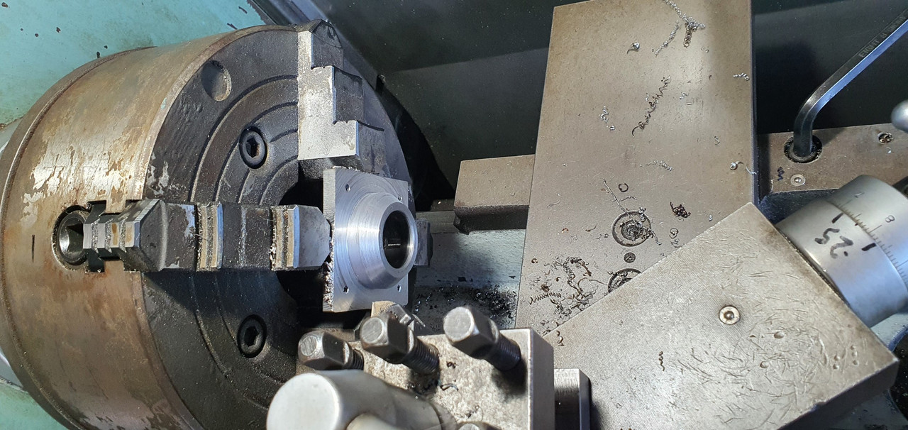
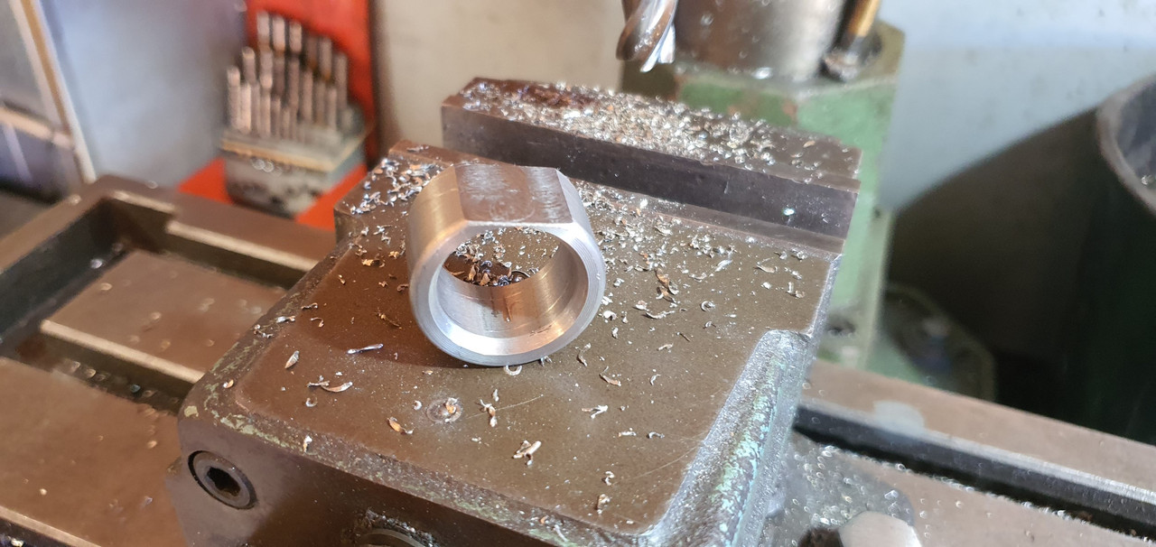
Now I needed a sturdy, slippery support to mount in place of the second universal joint. This will not only take back and forth movement on the shaft but also a bit of thrust loading created by the angle on the connecting shaft. I had already bought a lump of slippery hard engineering plastic with this application in mind when I had ordered the plastic for the flywheel thrust bearing a while back. It was bright yellow. Luckily not seen under the car as it would clash with the blue paint. I put a hole in it and machined the outside down.
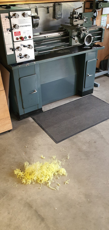
Which also created a pile of pretty swarf..
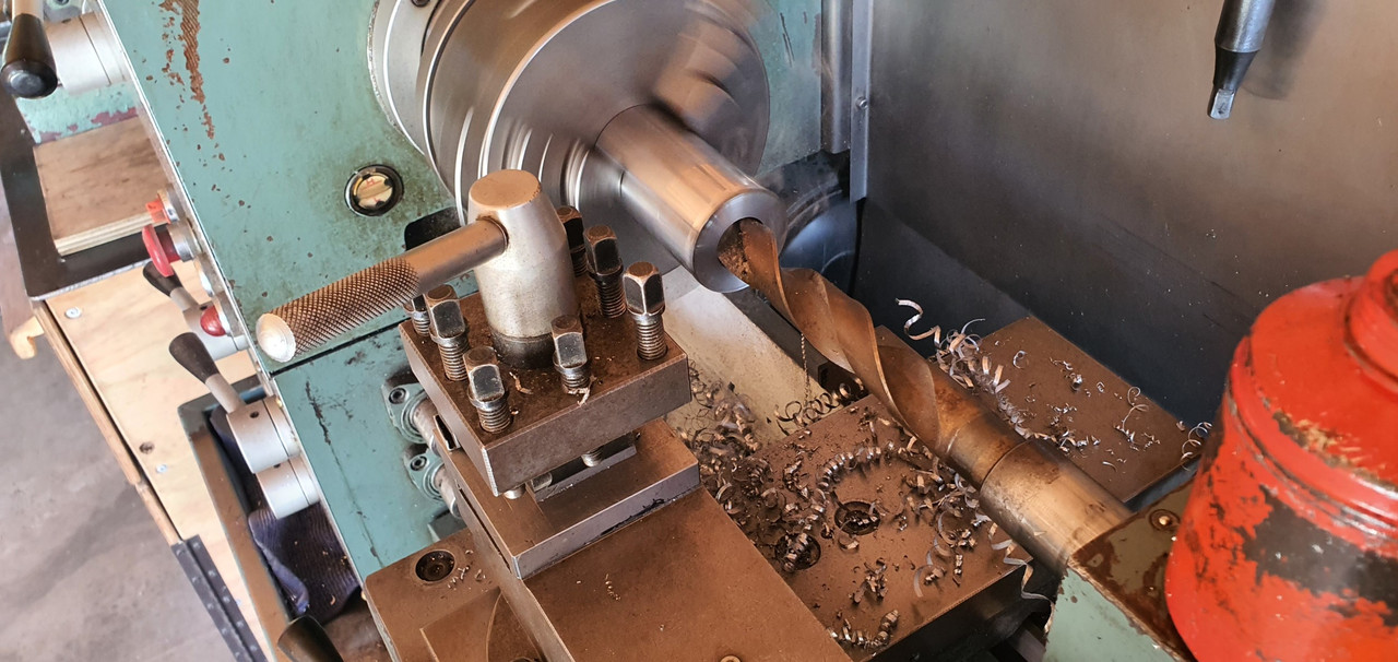
Then reamed it out to 1"
Still a bit tight so out with the adjustable reamers..
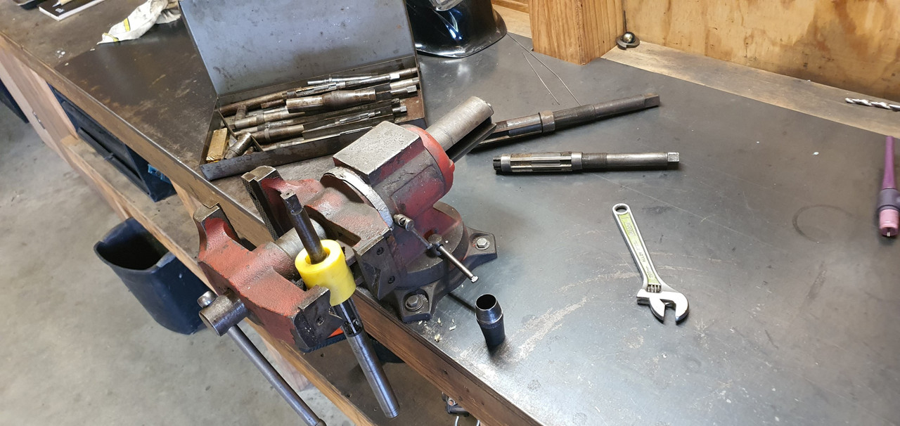
until it was just right...
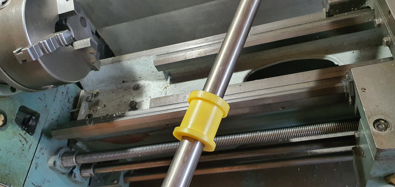
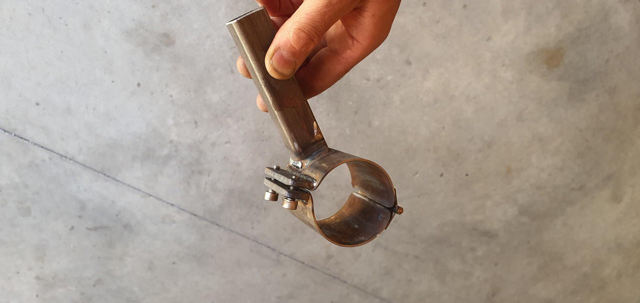
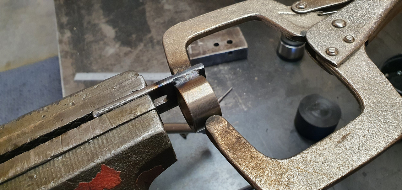
Then made a stainless cradle ..
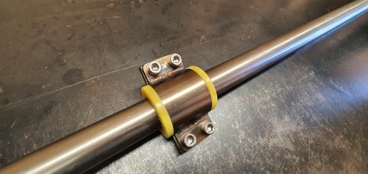
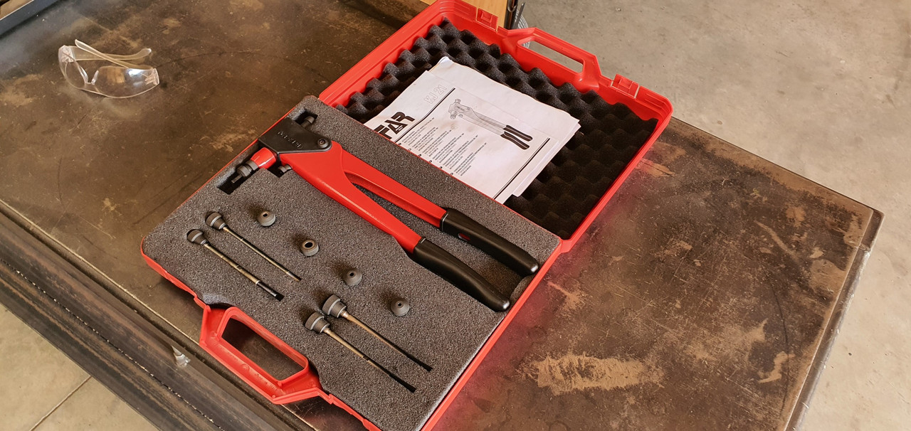
The cradle got some wings welded in place and I dug the rivnut tool out..
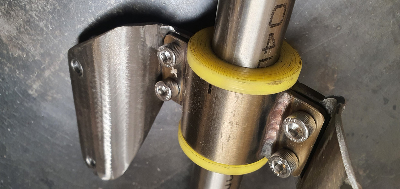
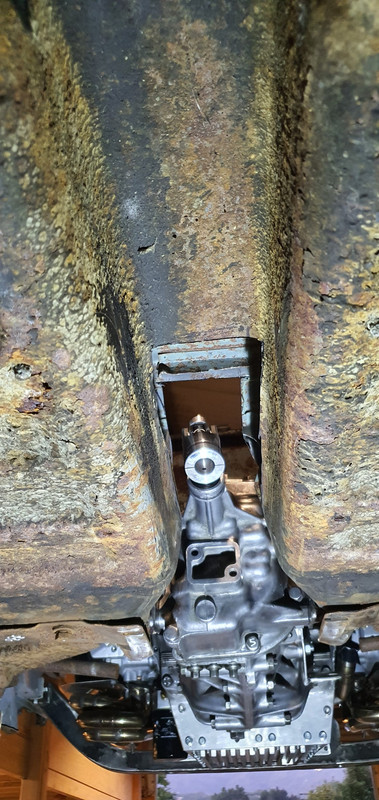
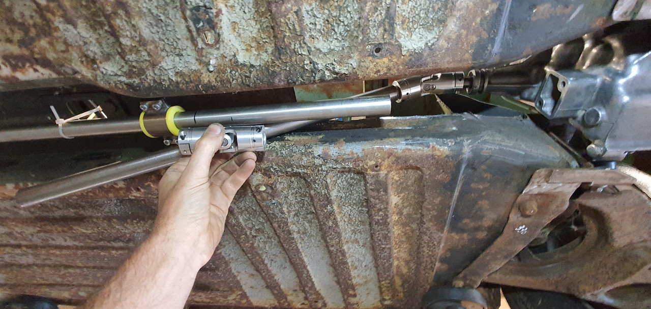
Mount now bolted in place in the tunnel I had to chop the last tube to the right length, weld on the end and bolt the universal in place..
The front end below the shifter was was standard imp stuff and this is where problems popped up to throw a medium sized spanner in my workings. The side to side gearstick movement across the gate was minimal. Ridiculously so. Like about 1". Or 25mm in new money. Yet the fore and aft movement was about right. But quite stiff.
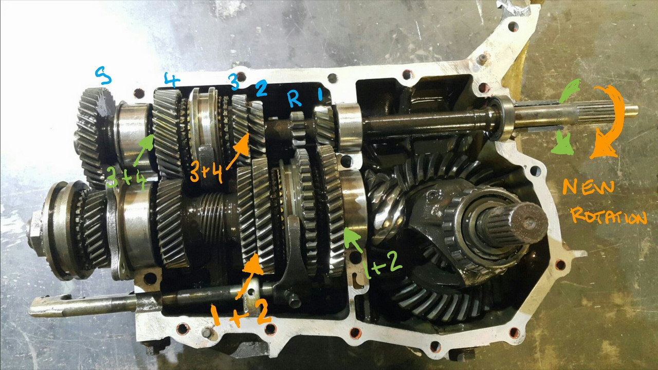
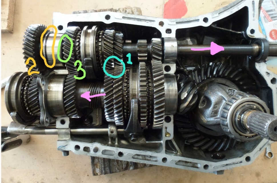
I was contemplating why this was so and what I could do to remedy this when I also noted that 1st gear was where 3rd was and 3rd was where 1st was.
Poos.
Four years ago when I had compared the Subaru gearshift pattern at the box to the imp unit I thought they were exactly the same. But I had not accounted for the reverse rotation taking place under the imp gearstick. Also I never really thought much about how little of rotation the Subaru box needed on its shifter shaft to shift the internal selector across the 3 rods. Its a tiny amount, like 3 degrees say. Whereas the Imp box has a shorter internal selector and requires more rotation at the shaft. Hence the Imps gearstick knob only moves a teeny bit when coupled to the Subaru box. But the Subaru box has a standard/similar amount of rod movement within (ie 1-2 and 3-4th) which was going to make things trickier to fix.
Simple linkage/leverage multiplications that is easier to see than explain.
Sorry if your brain hurts.
I had to hurt my brain a little bit to suss out a solution but there was only a little bit of smoke.
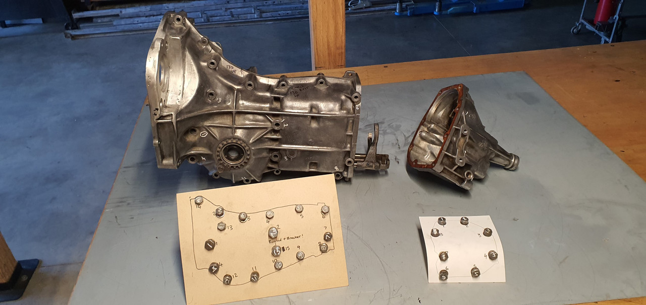
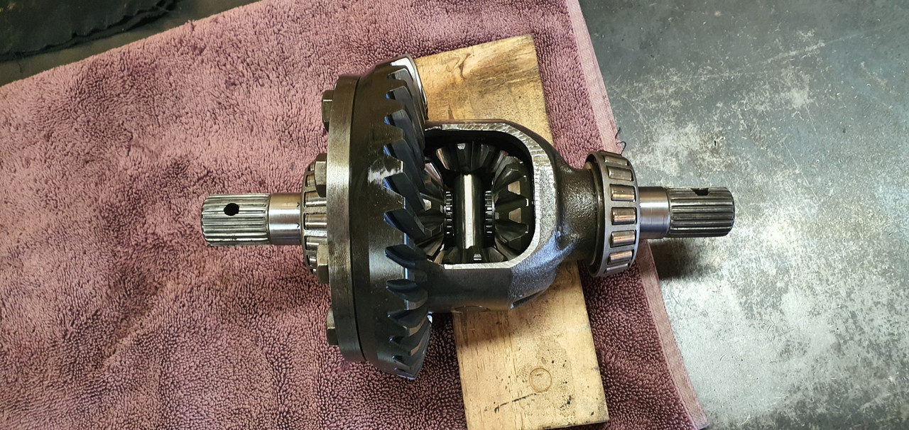
The reason the scooby box is different becomes obvious when you see the scooby shifter setup. Which luckily I can show you because last week thanks to a Subaru leone owner on oldschool.co.nz forum I was put onto a local fella to me who happens to have many old Leones and Brats kicking about his property and he had a spare leone front wheel drive box that I wanted (always handy just in case...)
His property is amazing!!! Long 4wd only driveway up to a ridgetop house with stunning views out over Tasman Bay. Old leones just kicking about...

Luckily we have our trusty old 4wd Hiace and that became the days gearbox transporter...
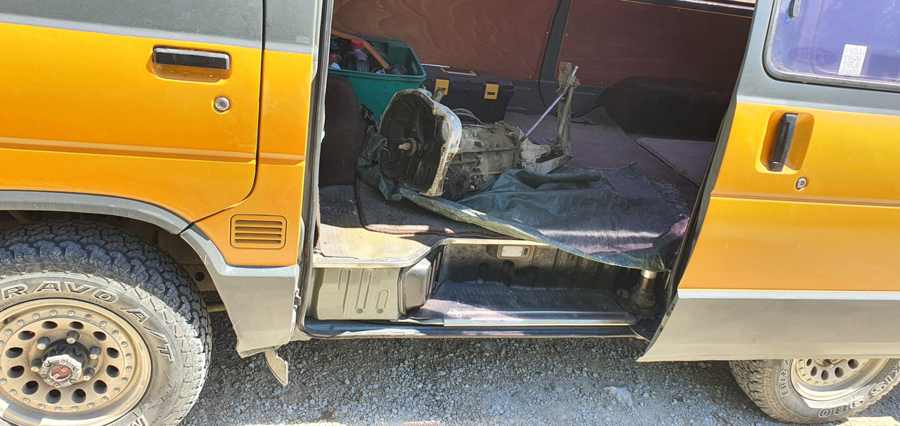
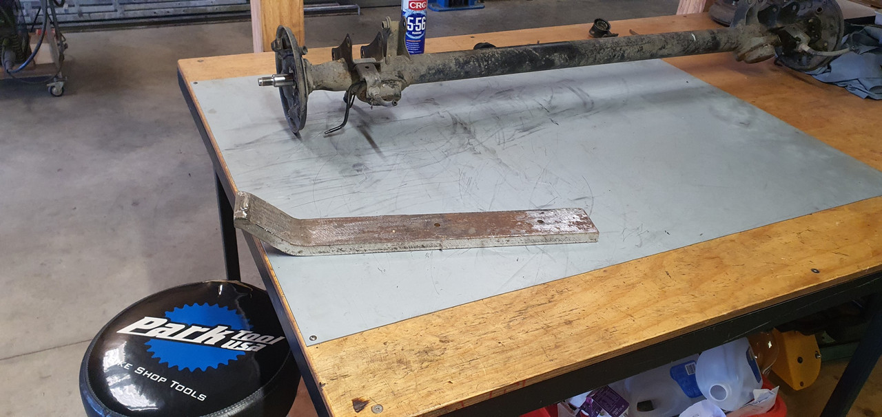
Box on bench. Look at that shifter mechanism...
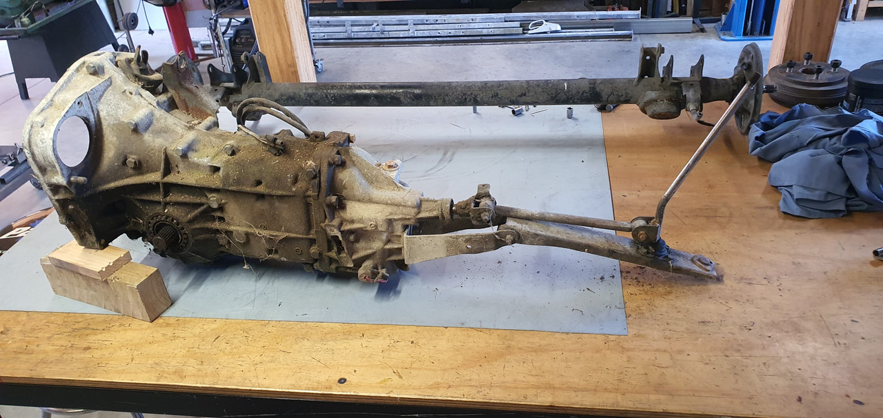
The shifter rod attached to the gearstick only rotates a tiny amount when the stick is moved sideways across the gate. But the rod moves 10mm in each direction when shifting for and aft. Simple. Robust. Very Subaru.
I can't copy it though because I have turned my box 180 degrees. No matter where I put my pivot point (below or above) I'll have one of the planes working backwards.
So I decided to build a new shifter base setup. The most important thing was to reverse the rotation so the gearstick pattern is correct. The imp pivot point needed raising to allow the offset shaft end to be rotated to above rather than below the centre line, so reversing the across gate movement. I would add the ability to adjust both rotation and lineal movement.
Started with a new pivot cup because I was not happy with the worn and Barried pressed steel item..
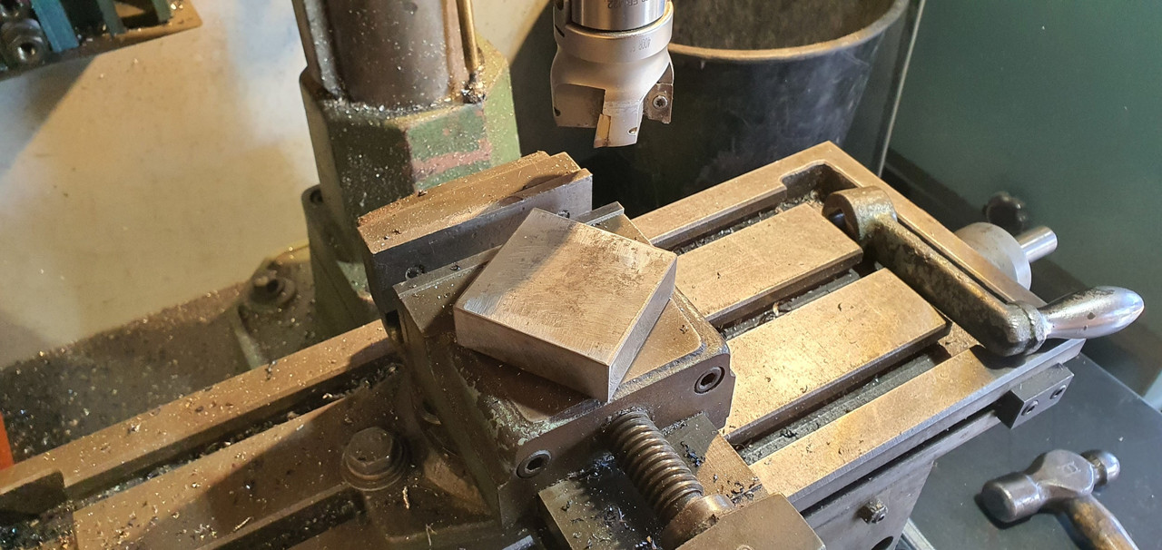
I dug out a large lump of steel bar...
Chopped out a square and cleaned it up in the mill..
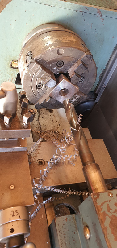
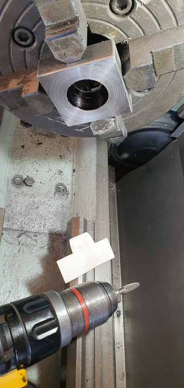
Big drill = big hole..
Rough machined out a cup shape. Cut a form in cardboard to suit the brass ball and used a die grinder bit to finish the shape...
Grinding paste time...
Slots for pivot pin..
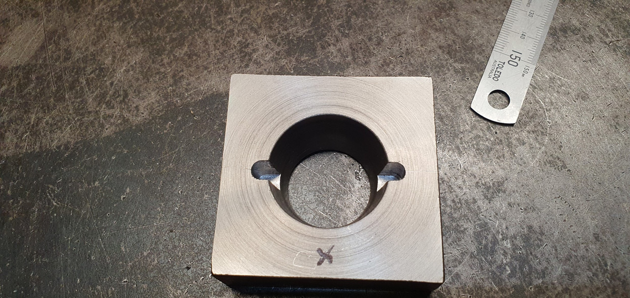
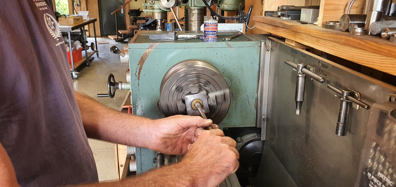
Lightened the lump down..
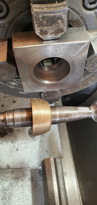
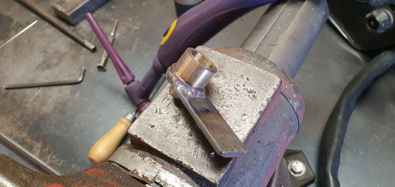
Built the shaft up with weld and machined it down so I could add a lower pivot point.
Milled some steel like so..
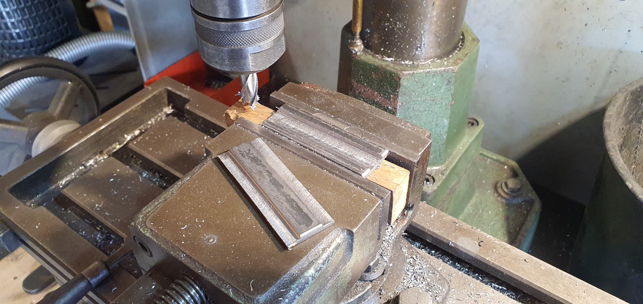
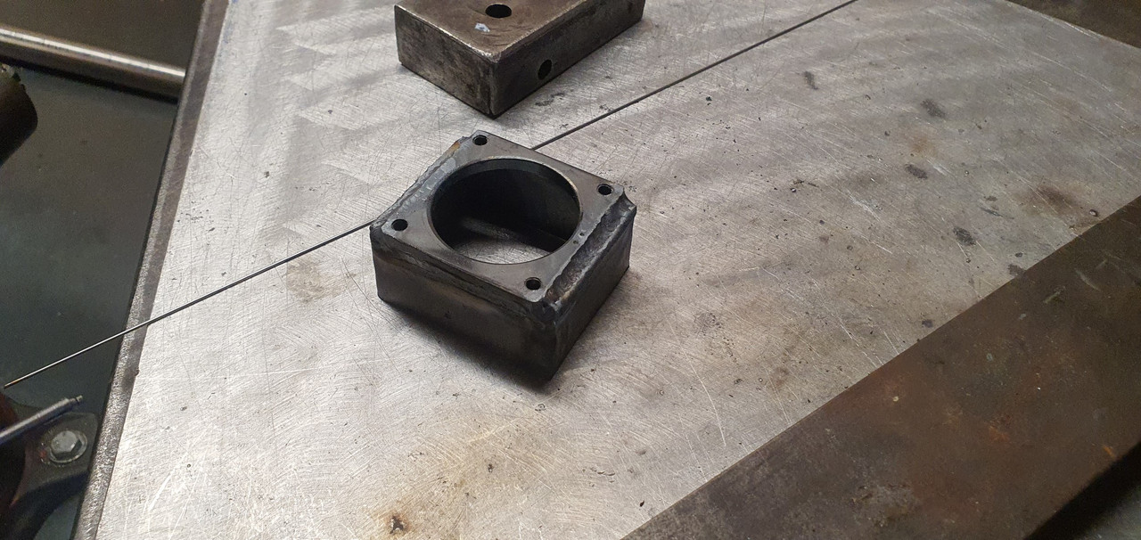
Welded a boss on..
New socket for shift lever ball end...
Cut out Barrys previous workmanship...
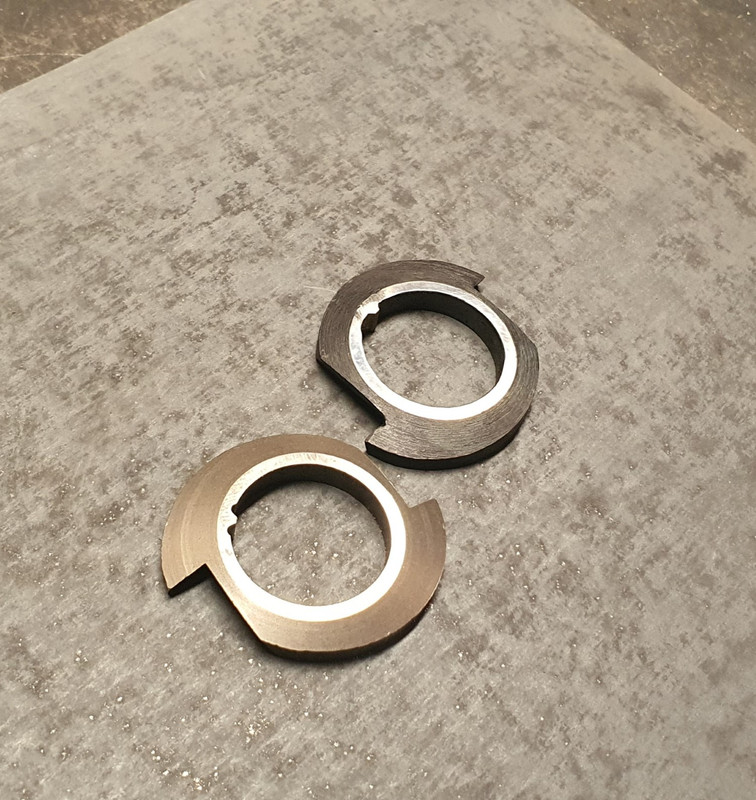
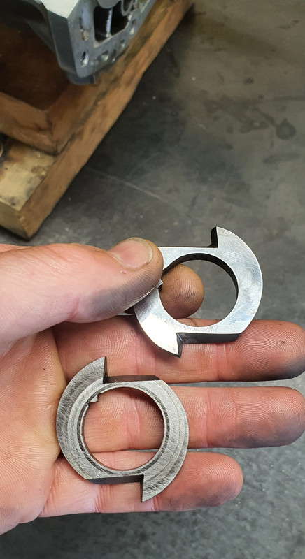
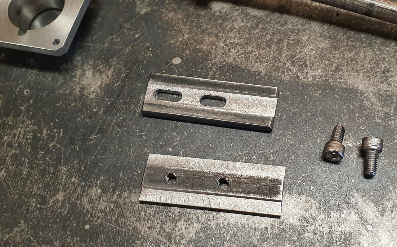
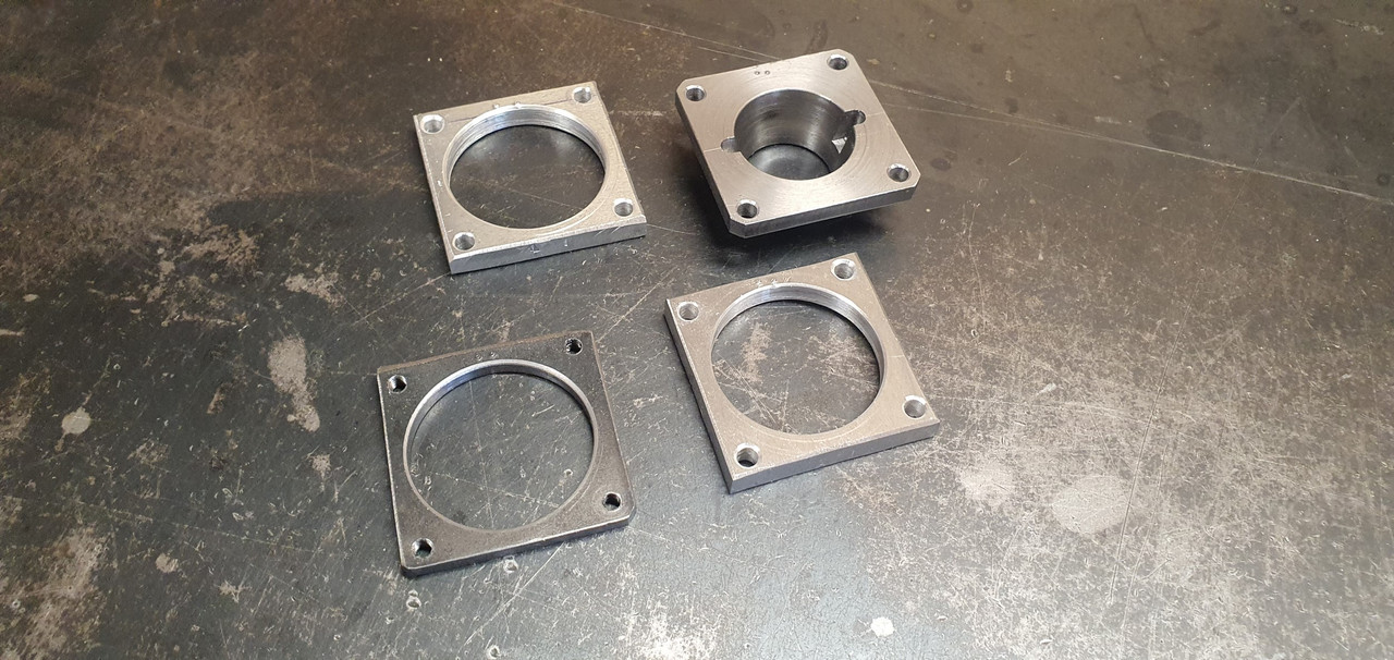
Machined up some spacers and a base plate..
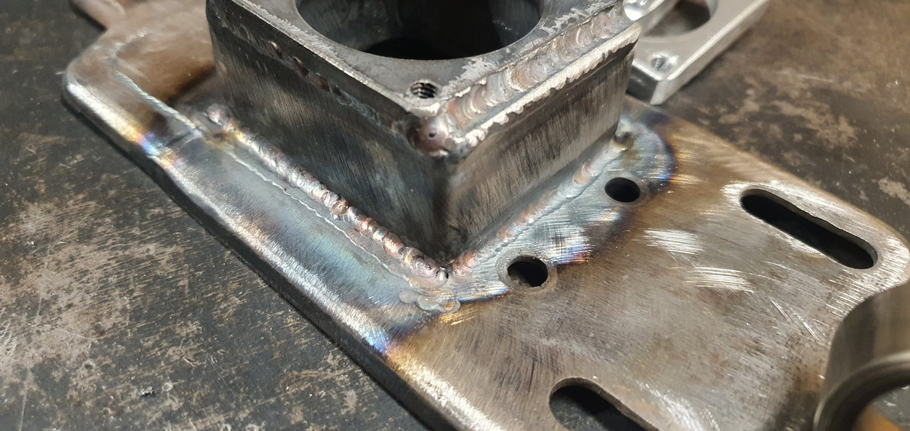
Welded up a little tower (my stainless and steel tig welding is definitely improving, helped muchly by realising that not being able to see what I'm doing does not help much and finally admitting to my age and buying some reading glasses....)
Welded tower to base..
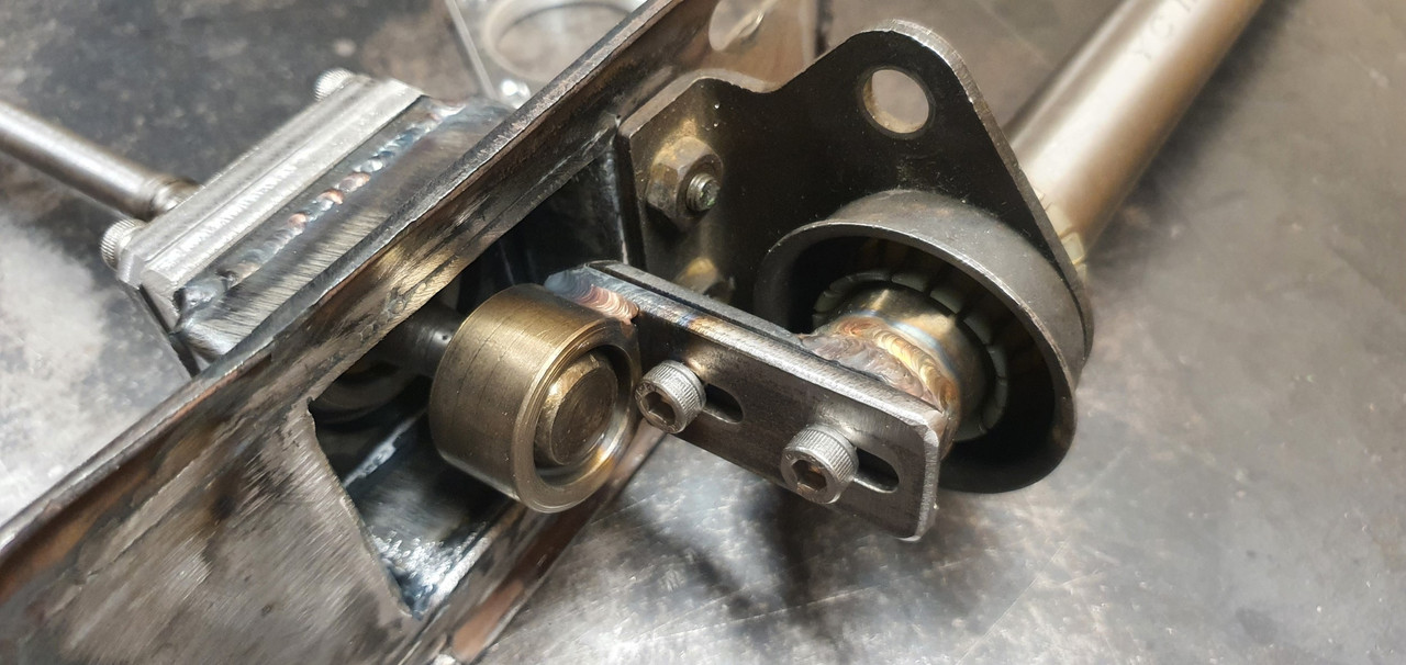
Now all together please...
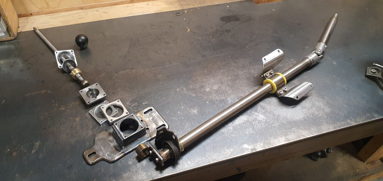
Bolted together. You can spot the adjustable rotation, which the spacers allow for, along with adjustable pivot point.
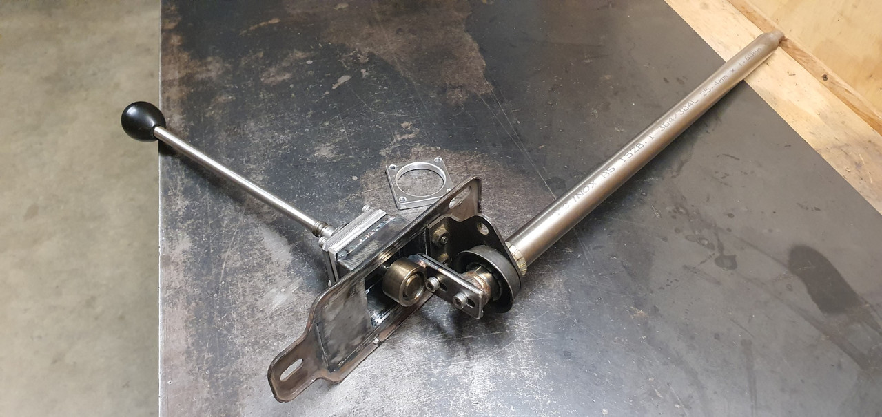
In place...
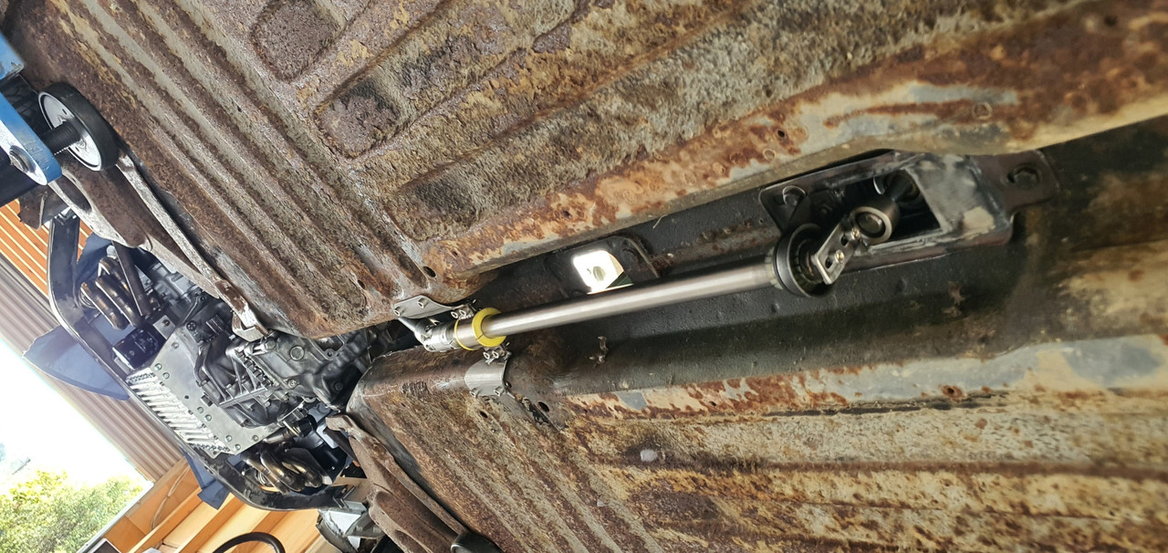
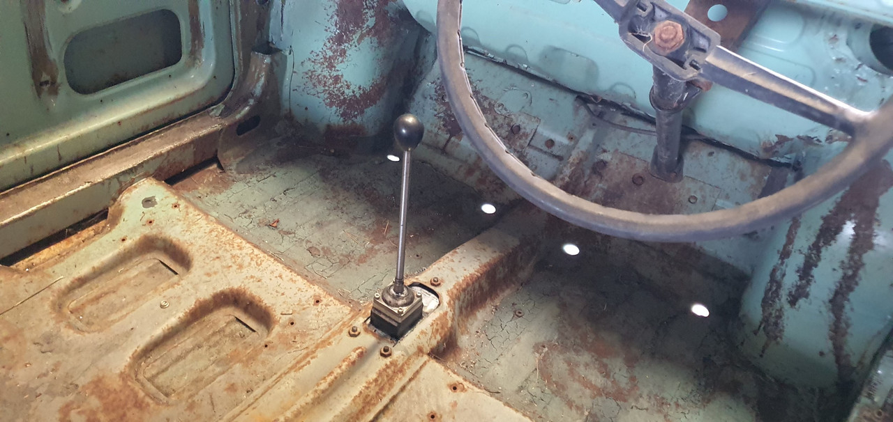
Yay- it works! The shift pattern is correct and the action is much smoother. The spring loaded indents on the internal gearbox shift rods are quite stiff, which I noted was the same on the other box with its stock shifter. Its a bit baulky to push past the synchro baulk rings into gear but I think will feel better when the gears are actually rotating. There's certainly no slop in the system and it feels very mechanical - not rubbery. I now note how much flex there is around the shifter base in the imps tunnel (granted a very rusty shell..) Its something I might just try to stiffen up on my blue Imp when fitting this lot in.
Phew. That was a little mini engineering mission I was not expecting but that's this project in general