Page 1 of 3
73T - Brake & Suspension Refurb - Part 4 - Front Install
Posted: Sat Jul 11, 2009 9:31 am
by Highfield
Having finished up on the rear installation, bar a few finishing touches, I now turn my attention to the front.
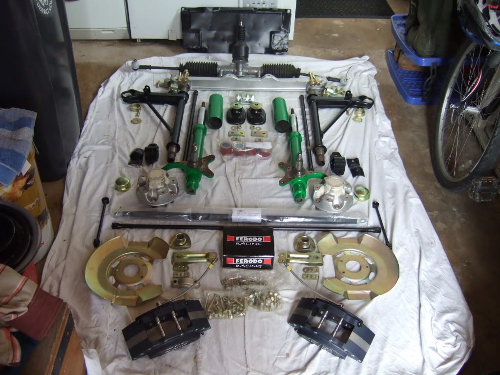
Plans for today were to get everything together to see the scale of the task, and then get the front aluminium crossmember and steering rack installed, along with the preparation for the ER Polybronze Bushings and Low friction Control Mounts.
So here is what I will start with, and and update will follow after the first part of the install.
Ian
Crossmember, Steering and ER low Friction Mounts
Posted: Sat Jul 11, 2009 5:39 pm
by Highfield
So here we go !
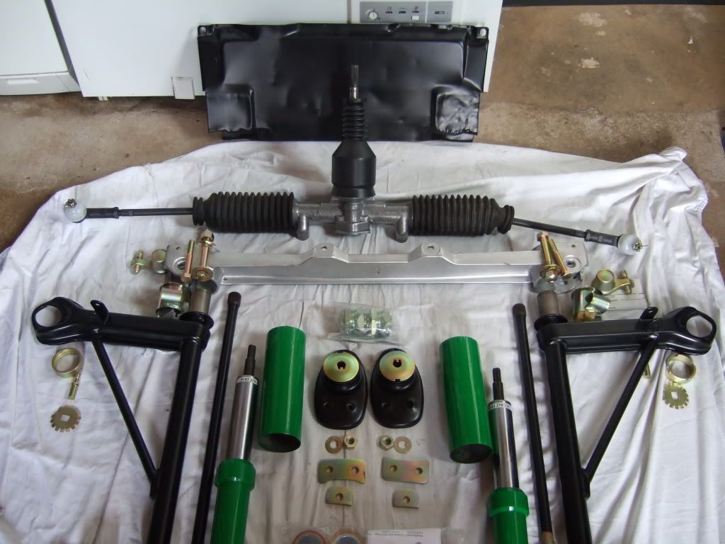
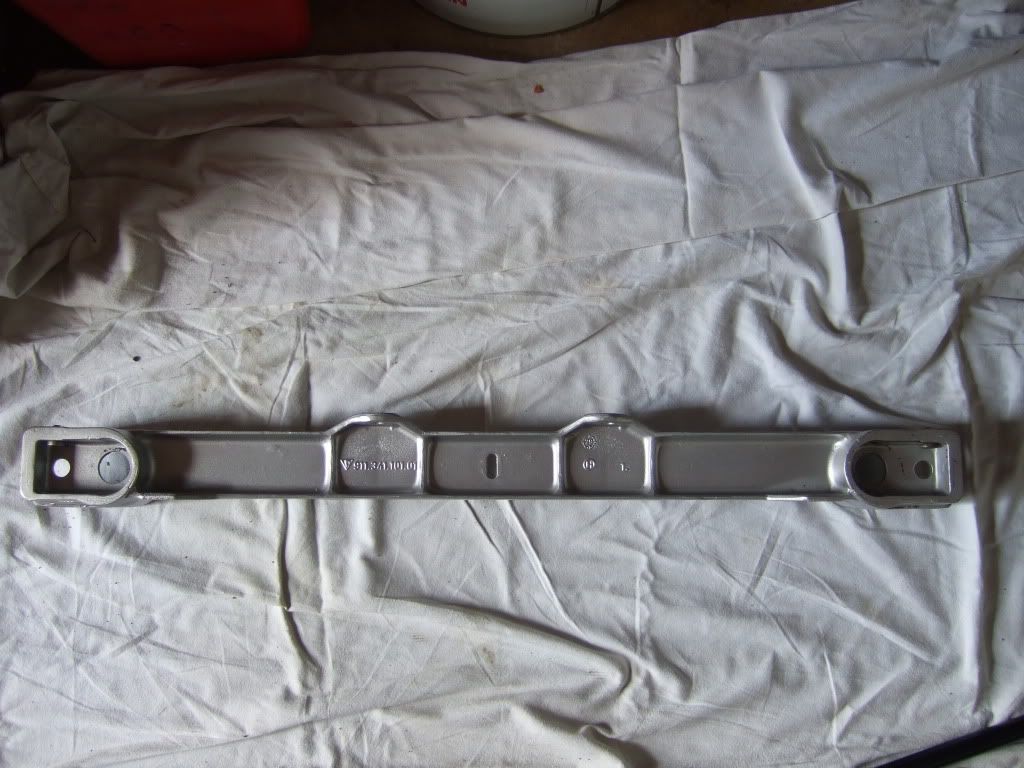
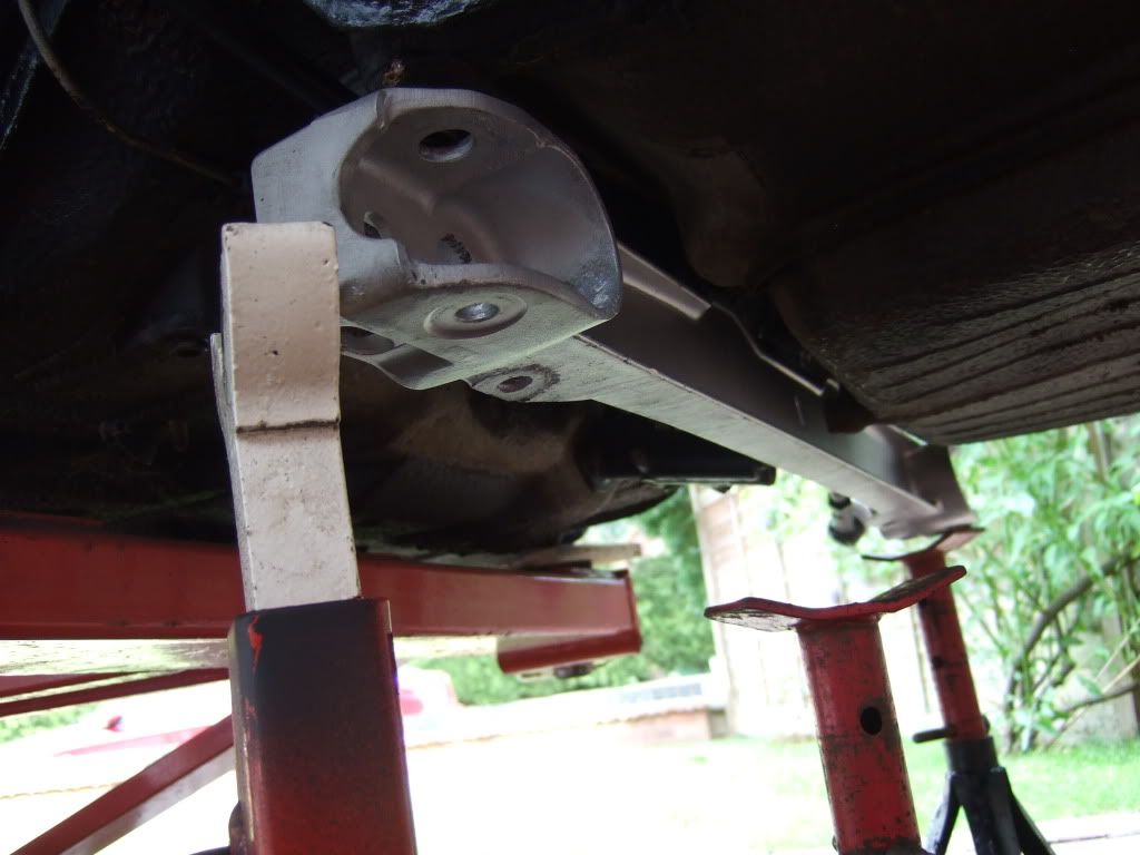
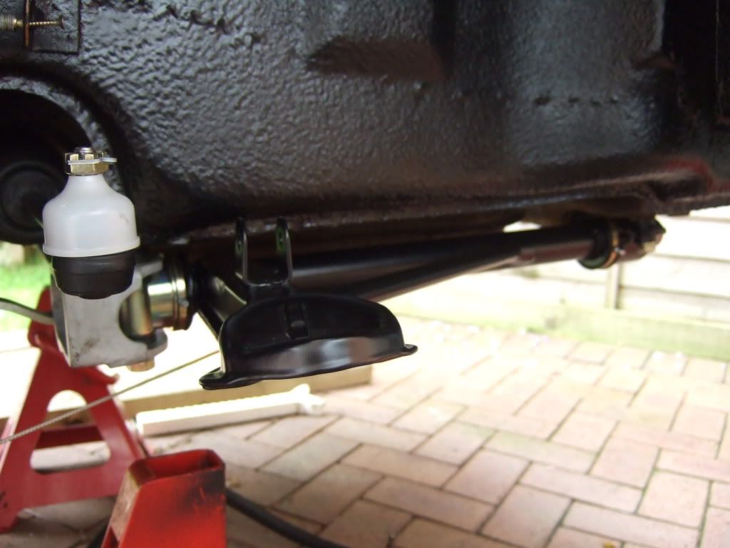
First up is the vapour blasted and super light weight aluminium front cross member - it has hard to believe how light these are.
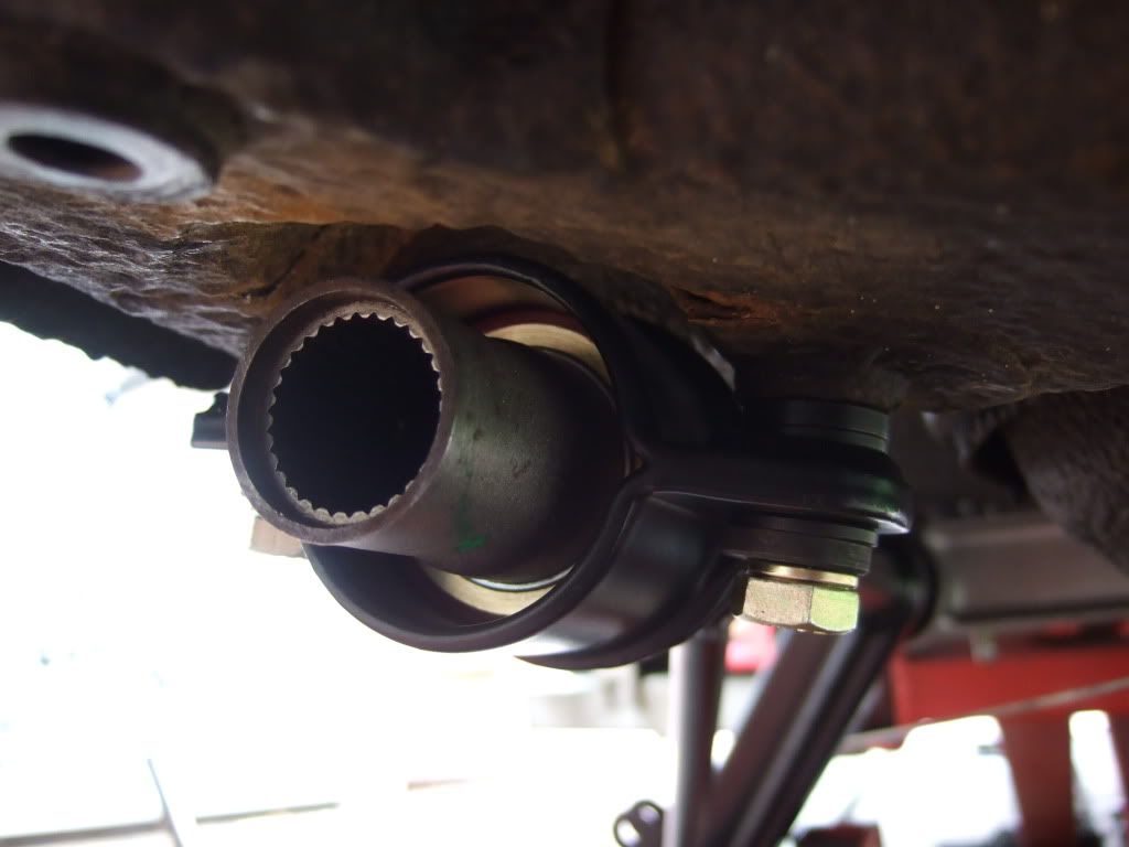
I decided to mount the steering rack with the new turbo tie rods to the cross member and install froim under the car in one piece.
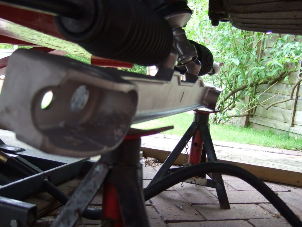
The assembly is loaded on to two axle stands and then eased up one side at a time, being careful to get the steering column aligned with the UJ as it goes up. Easier with two people, but axle stands work well.
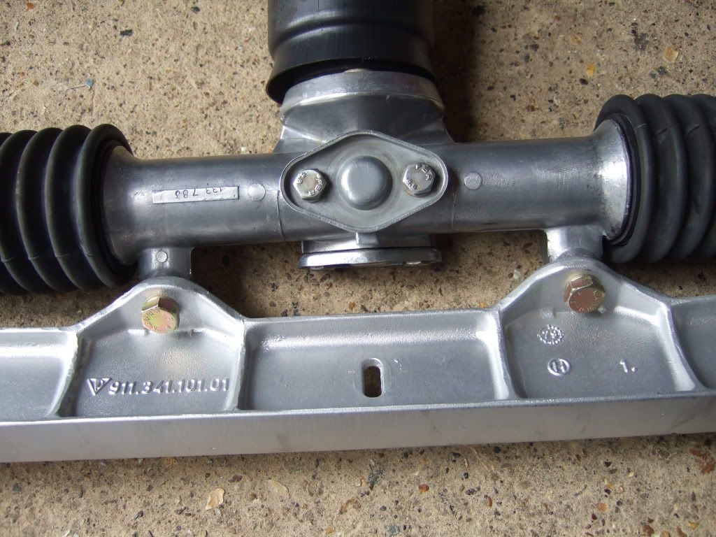
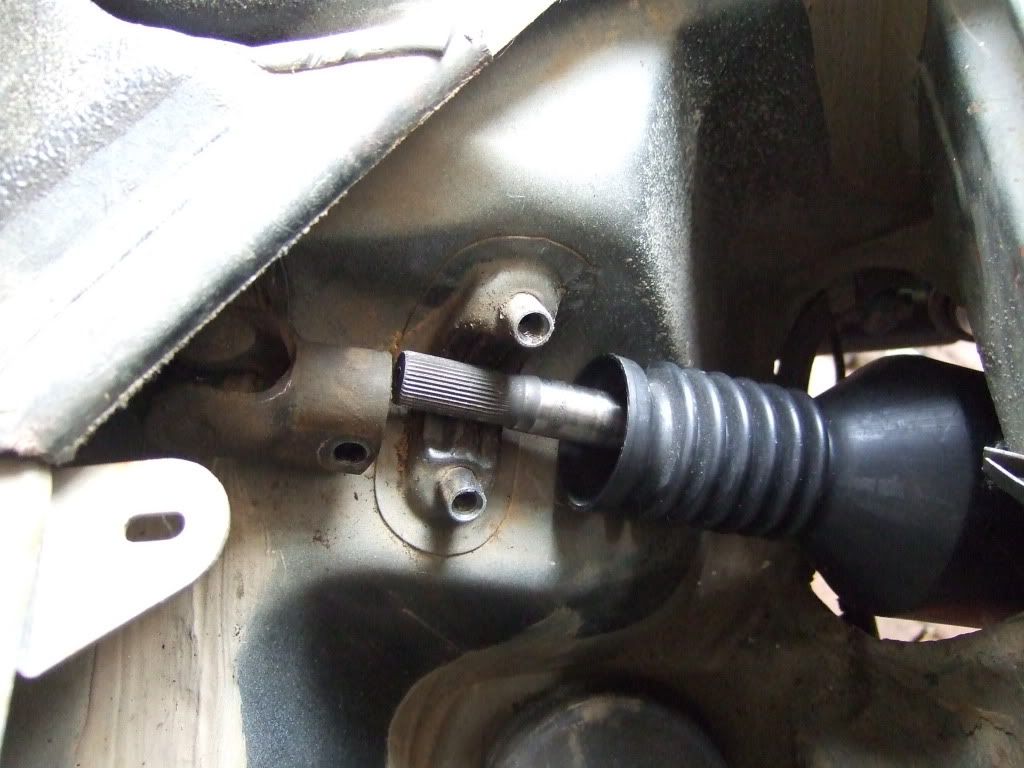
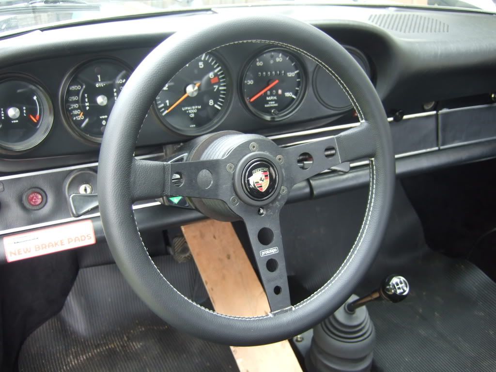
Remember to centre the rack and steering wheel before mating the UJ with the rack

Also, make sure you bend the tie rod split pins out of the way as they are a great point to take an eye out on if not careful.
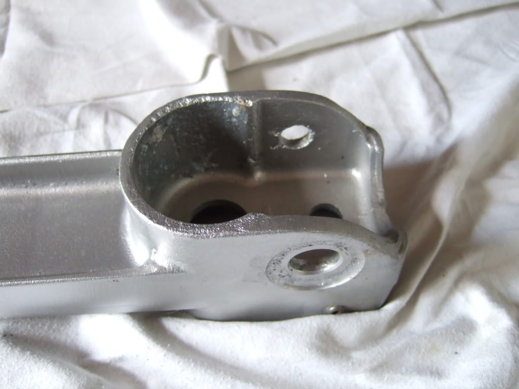
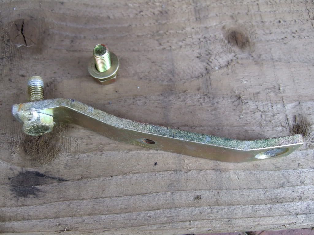
Then the replated support brackets with the welded on bolt threads push in to the cross member and locate on the lugs on the underbody.
Next up come the ER Low Friction Mounts before the axle stands can be removed.
Ian
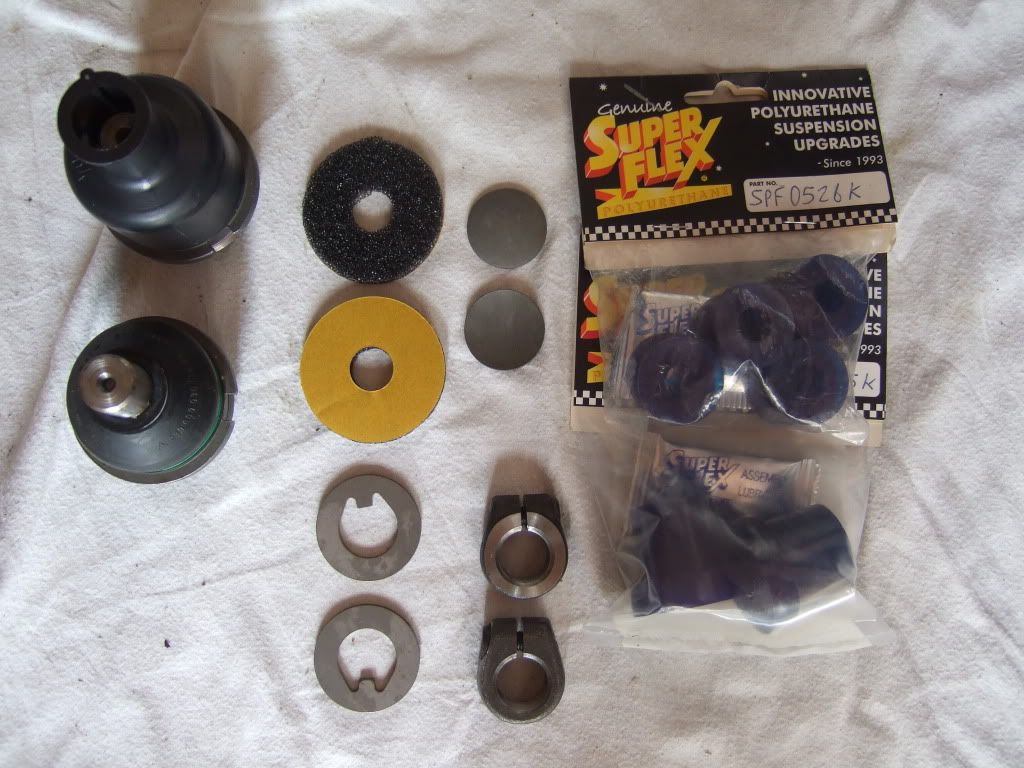
ER Low Friction Mounts
Posted: Sat Jul 11, 2009 5:48 pm
by Highfield
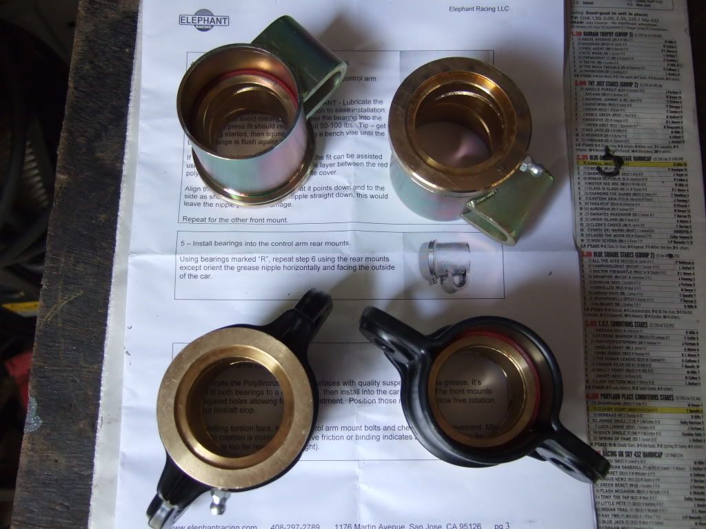
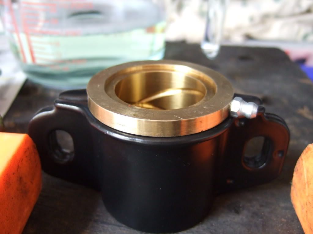
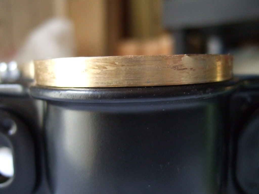
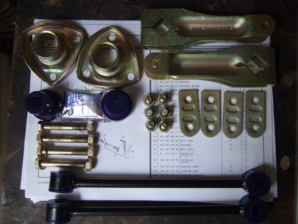
I have the ER Low Friction Mounts and Polybronze Bushings, so hopefully the A-Arm install won't be too much of a trouble - famous last words.
I followed Chuck's excellent instructions and used a 'big' press to install the bushings - they are a tight fit.
Shown here with the front mounts also ready.
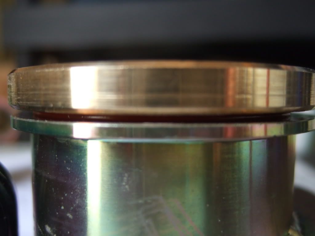
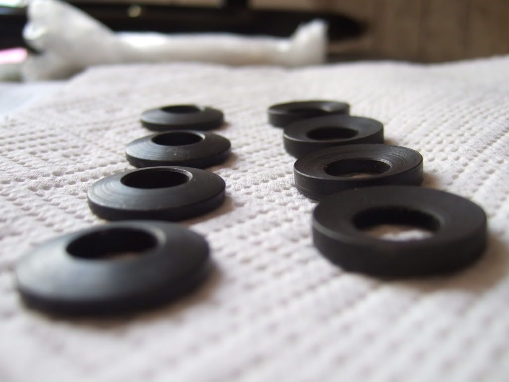
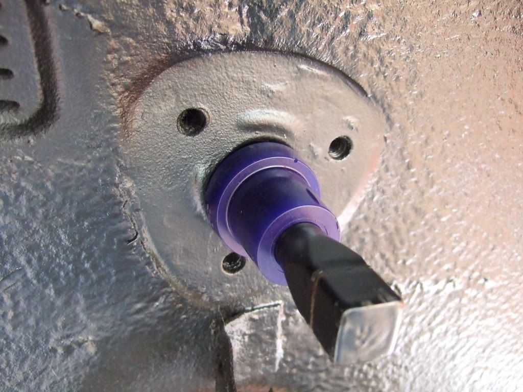
These are then placed in to the cross member and the concave and convbex washer set carefully setup and installed - take time to get them the correct way around.
Then the large mounting bolt, washer and lock washer are installed and tightened (not fully torqued) to allow the axle stands to be removed.
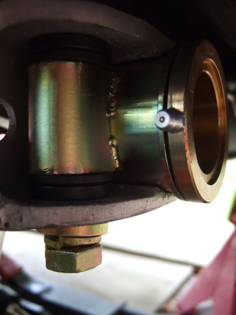

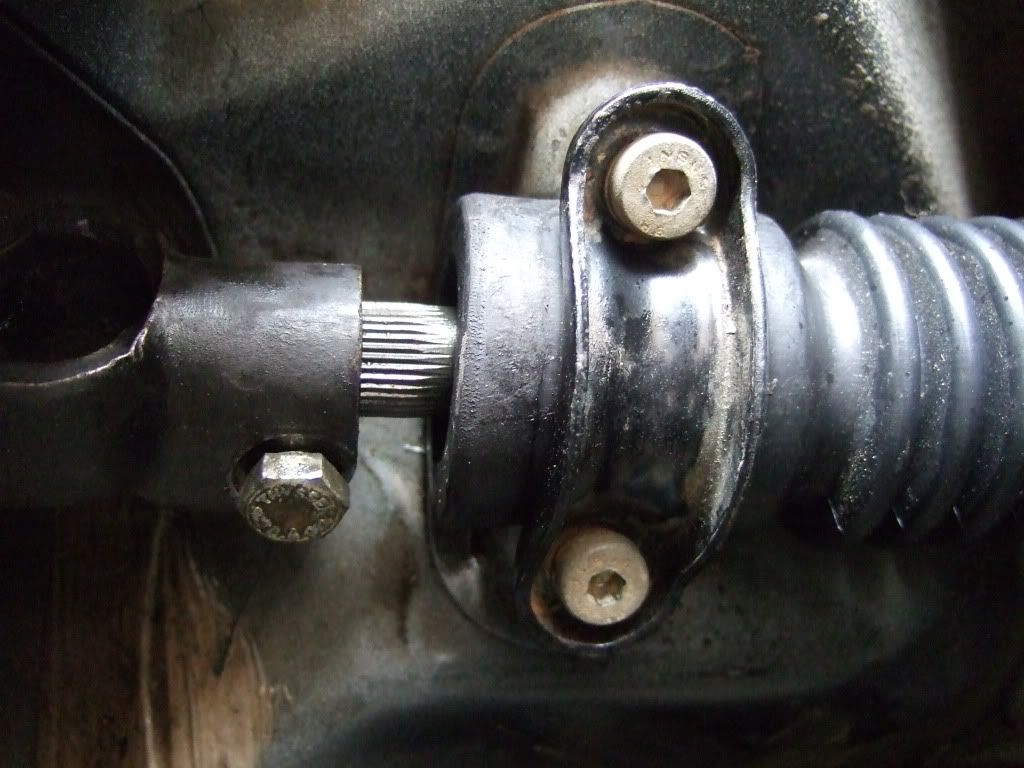
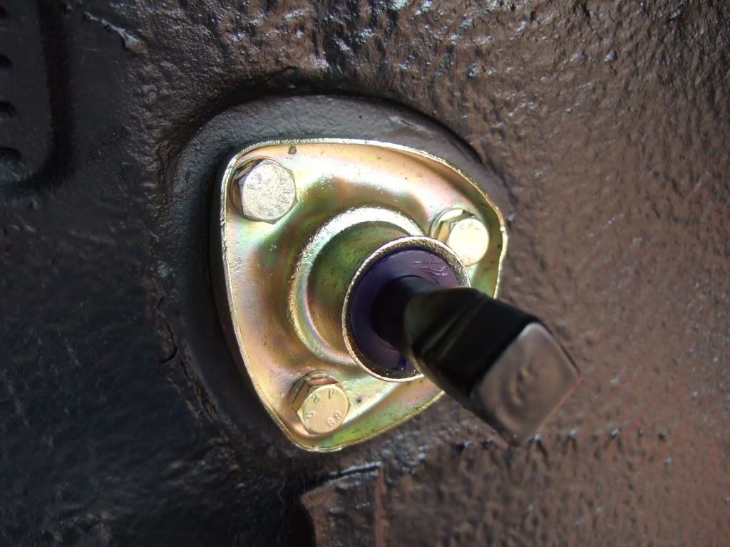
The last thing to do is to fit the steering shaft bushing and bracket and ensure the UJ is fully engaged the the bolt tightened.
So that is it for today, and next time it will be the A-Arms and ER Polybronze Bushings and front mounts.
Ian
Posted: Sat Jul 11, 2009 9:48 pm
by ross.mcw
These posts are like automotive porn Ian...
Posted: Sat Jul 11, 2009 10:29 pm
by johndglynn
Great posting mate! You've really got the hang of this stuff now

Posted: Sat Jul 11, 2009 11:12 pm
by Highfield
JG
They will be a little more spaced out from now as I am back to work on Monday, having spent this last week onthe car.
No fixed deadline, so it will get done when it gets done.
Ian
Posted: Sun Jul 12, 2009 2:49 pm
by oliveR
A-Arms
Posted: Sun Jul 12, 2009 5:07 pm
by Highfield
Yes oliverR, I am on to that bit - yours looks great there.
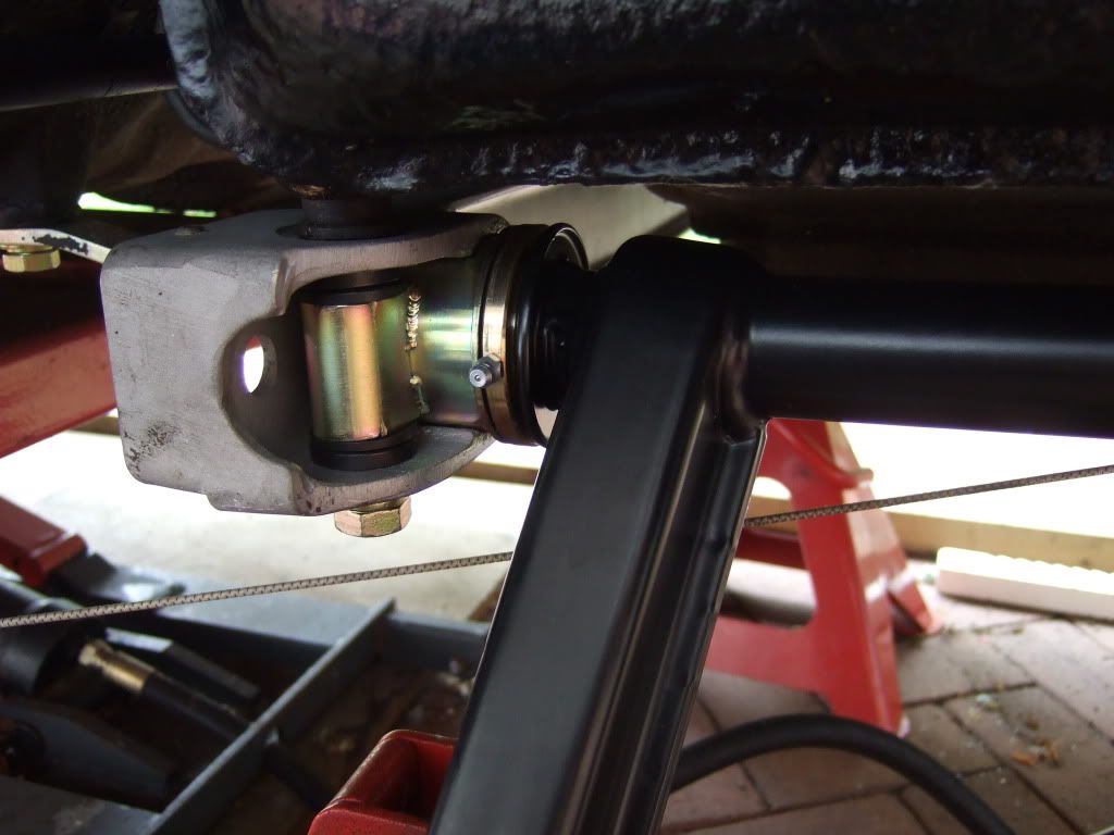
Today was the turn of the A-Arms and the ER Polybronze Bushings.
I had already JB_weld fixed the races to the arms, and pressed the bushings in to the mounts.
With the ER Low Friction Mounts already installed but not tightened in the Cross Member, I carry the A-Arm and mounts to the car. I also took time to correctly orientate the ER washers that affix the mounts to the front of the car.
It is then simply a case of inserting the arm in to the rear mount and lightly attaching the front bolts.
Then tap the washers as instructed to settle them and whilst rotating the A-Arm, tighten the bolts. I did this a couple of times to get the arms to fit with only minor resistance to movement. They do not swing up and down with no intervention, but are pretty good.
Do they have to 'flop' with no input from me ?
What are the torque settings for the A-Arm mounting bolts please ?
Ian
Posted: Sun Jul 12, 2009 5:55 pm
by peter stey
They should fall under their own weight. When I had them on my car it also took quite some time to get them setup right.
Posted: Sun Jul 12, 2009 10:35 pm
by Highfield
Thanks Peter,
Chuck replied and said they were OK if they took perhaps a couple of pounds force. My RH side is fine, but I think I will have a go at reworking the LH side.
Ian
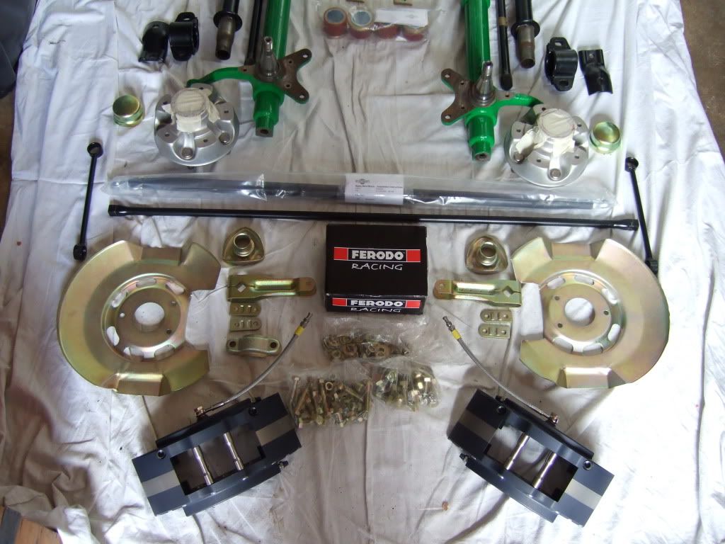
Anti Roll Bar
Posted: Sun Jul 19, 2009 7:26 pm
by Highfield
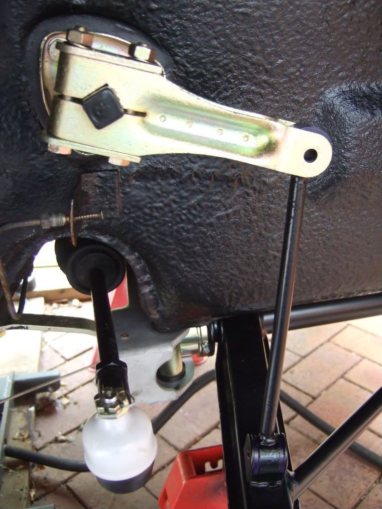
The Front ARB is next up, this being the standard 15mm bar, freshly powder coated with re-passivated arms and links, and new 'stiff' bushings.
The new bushings were pressed in to the droplinks using a clamp and pre-soaking in boling water - same as for the new bushings on the rear ARB.
The 8 X 40 bolts are nowhere to be found, probably lost at the platers, therefore the droplinks cannot at this stage be attached to the arms, but that is OK whilst I do the height adjustment etc.
The bar is slotted through from one side, centred, and the new bushings fixed in place. The cover plate is then torqued in to place.
The arm is then mounted and the long bolts torqued up.
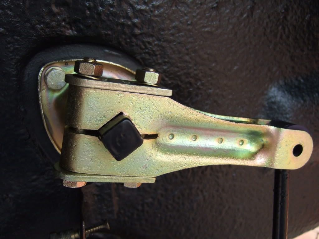
Final job for now is to fit the droplink but not fasten yet.
Ian
Torsion Bars
Posted: Sun Jul 19, 2009 7:37 pm
by Highfield
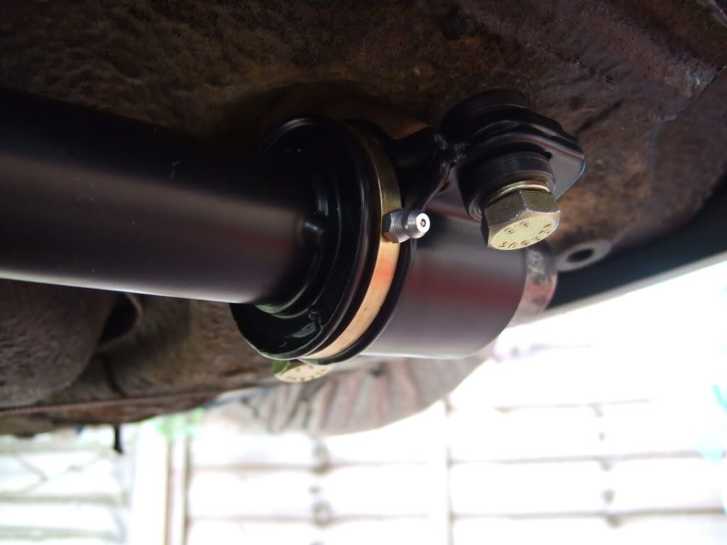
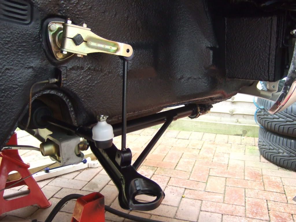
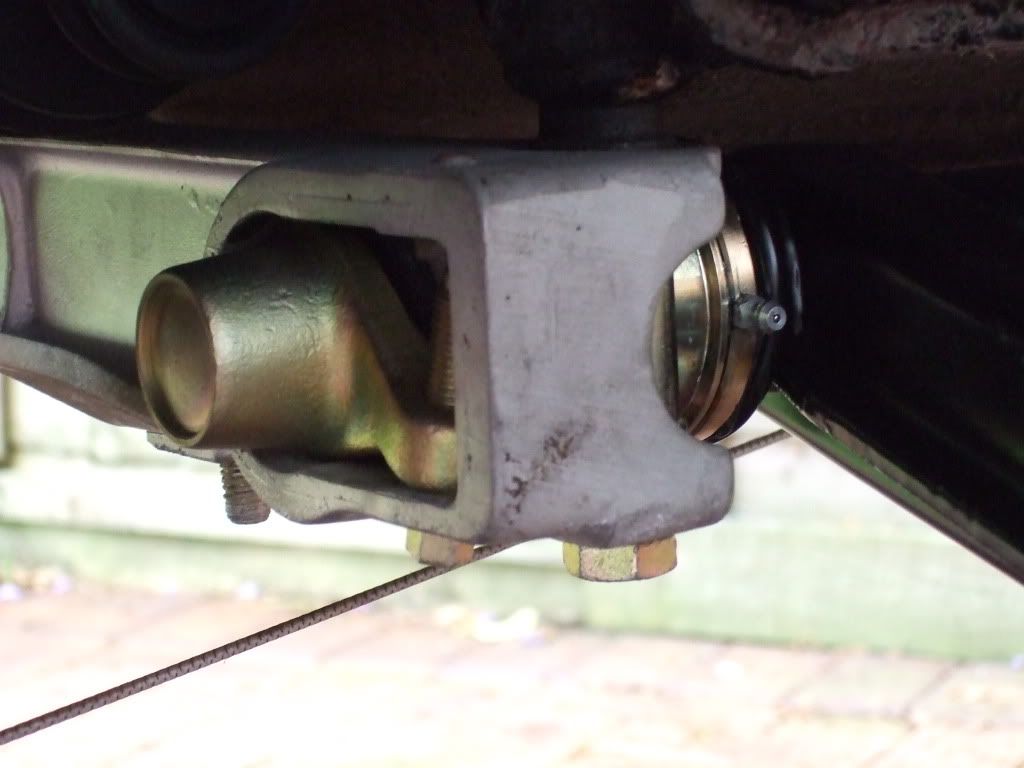
I decided to fit the torsion bars (standard 19mm - Used from Tom1390Racing on Pelican as on back order in Porsche Europe) and index as best I can for now.
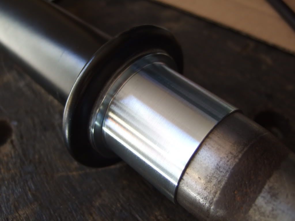
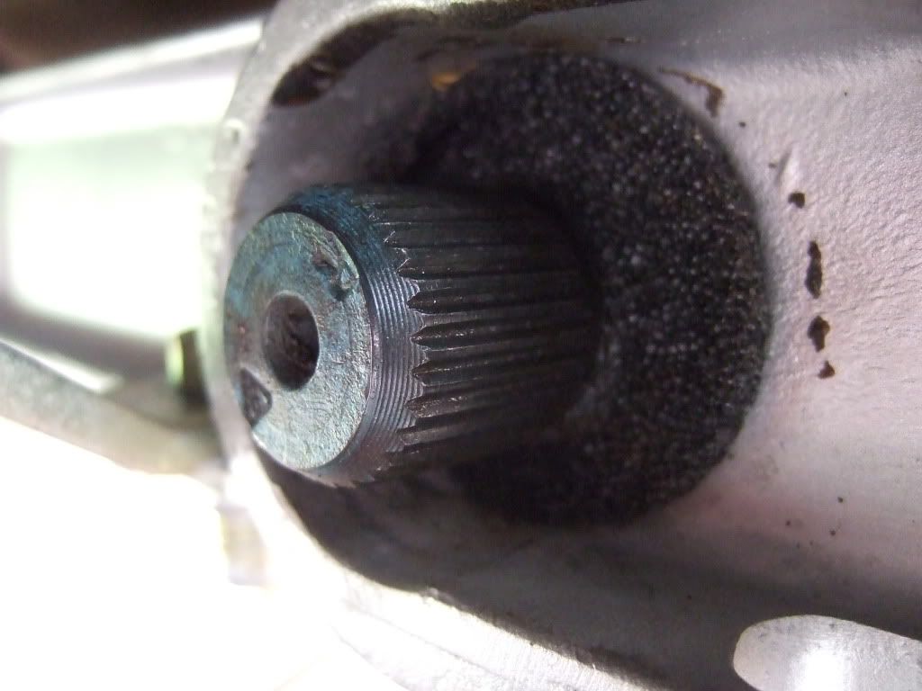
The bar is greased and inserted from the front, pushing it back until the rear threaded section is exposed for the adjuster to locate on to.
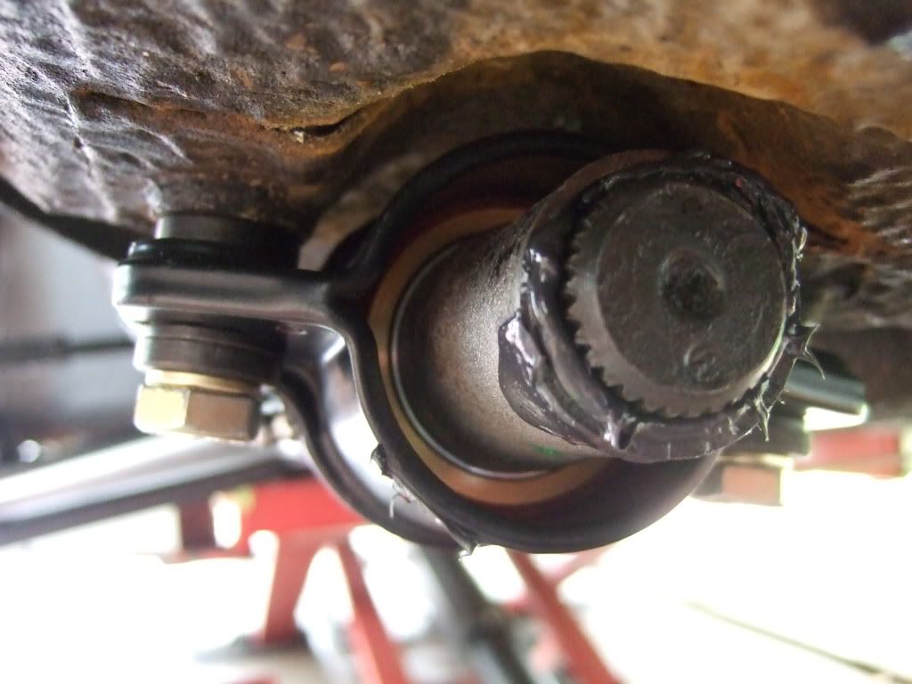
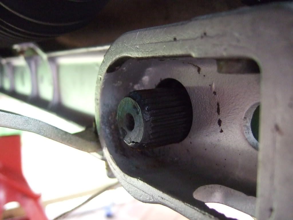
I have new foam gaskets and front dust covers as well as re-plated adjusters.
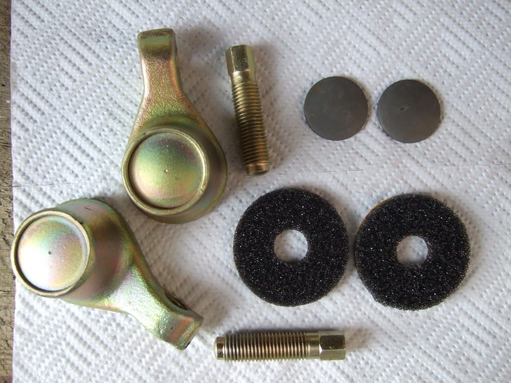
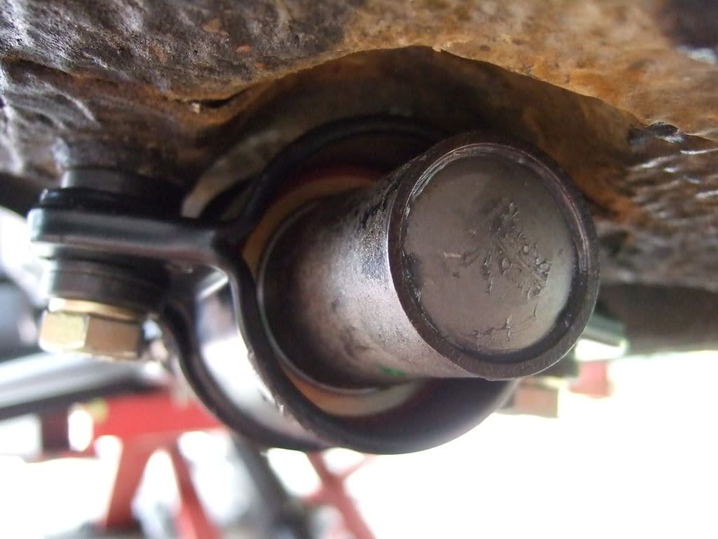
The dust cover is 'tapped' in to place.
The foam seal is stuck in place.
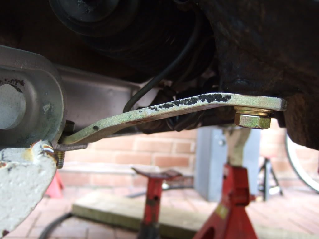
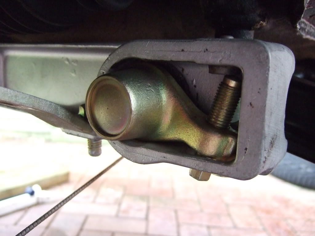
This is where I do guess work. How do I know which angle to set the A-Arm at in order to install the adjuster with no strut etc. ?
The Haynes manual mentions the A-Arm being 10 degrees below the Crossmember. Set get my angle setter and posiotn the A-Arm.
I then slot the adjuster over at the mid point of adjustment and insert the screw. Absolutely no idea what ride height this will give.
Does anyone have a more accurate way of doing this at this stage in my rebuild ?
Note photo was taken when adjuster was set incorrectly.
I now need to wait for a few bolts before moving on, and some channellocks to help me fit the ER Front Monoballs.
Ian
Posted: Sun Jul 19, 2009 10:10 pm
by 911hillclimber
Just spent most of the day cleaning under my 4 wheelarches and touching up 20 year old smoothrite etc.
Looks still like a scapyard compared to this high-end rebuild.
Fab work!

Posted: Sun Jul 19, 2009 10:40 pm
by Highfield
911hillclimber
It is however taking me a long time, and I can only do it through assistance of those far better qualified than me through these forums etc.
Your Lola looks spectacular, and that is what I call 'proper' engineering.
I haven't got to the hills this year, but will see if I can catch a glimpse later this year.
I see you are in the West Midlands, so perhaps not too far from me.
I would love an opportunity to look over your 911 and the Lola.
Ian
Posted: Mon Jul 20, 2009 6:26 am
by 911hillclimber
I'm very close to Wolverhampton, so close!
You are more than welcome to see the Lola.
I hope to hillclimb it at the next Shelsley Walsh in Aug I think, so that is close to you too!


