Page 7 of 30
Re: 964 C2 - Rolling Resto
Posted: Tue May 21, 2019 10:23 pm
by rhd racer
So then onto the engine mount, which had been 'modified' with a new hole adjacent to a sheared 6mm bolt for one of the tinware sections or heat shields....
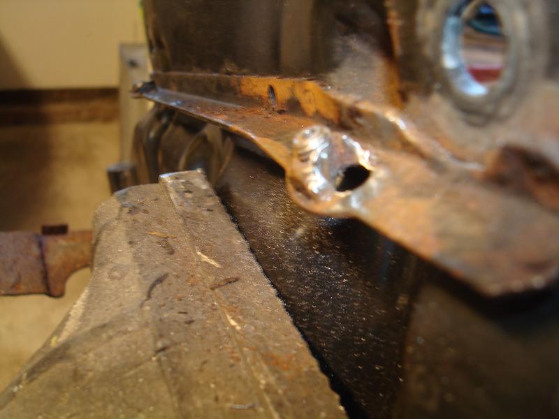
It also looked ropey
So after plugging the hole with weld and drilling a pilot hole it looked like this
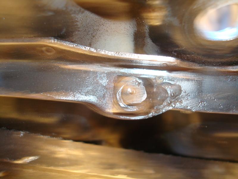
I tapped it and reformed the lip but wasn't happy with the way a bolt went into it - something was just gnarling the thread slightly. Rather than ignore it and regret it later, I cut off the original captive nut and welded on a hex nut. Not OE looking, but done, and invisible anyway.
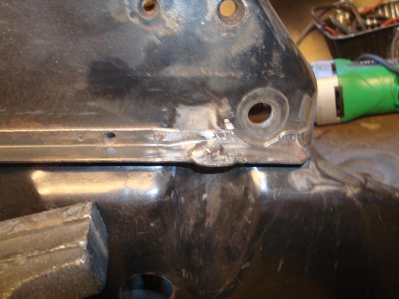
So with that done, and the ugly knocked off the rear ARB, everything needed rust proofing. Tick
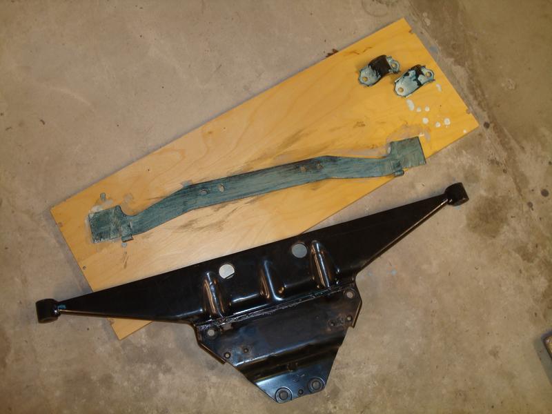
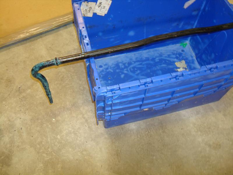
The green shade is the reaction of the treatment on the rust. It all is now completely rust free and looks like it has been varnished. Brilliant stuff.
And that's where I am today - just painting required now for those and the tinware I have acquired.
Re: 964 C2 - Rolling Resto
Posted: Wed May 22, 2019 6:12 am
by sladey
Nice one
Re: 964 C2 - Rolling Resto
Posted: Wed May 22, 2019 8:43 am
by Lightweight_911
.
Great to see this approach (which, sadly seems to have virtually disappeared) whereby parts are refurbished/cleaned to preserve their 'used but well-cared for' appearance ...
Re: 964 C2 - Rolling Resto
Posted: Mon May 27, 2019 4:34 am
by Daveuxb
rhd racer wrote:Now the chain guides / retainers / pressure tensioners all fitted up.
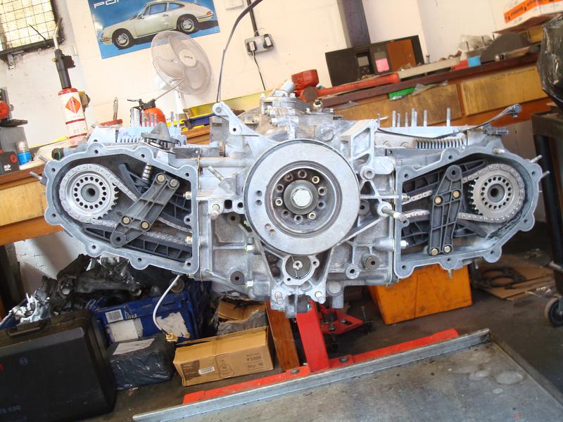
You will see the nuts securing the cam sprocket wheel that we don't know the proper name for has been removed. That is because this is a crucial part of the build. Basically, because the engine is horizontally opposed, there is a factory tolerance for ensure that the chains run squarely to each other. In essence, you place a steel rule across the case on a diagonal below the front pulley. You take a measurement from the rule to the intermediate shaft bearing, and then take off the depth of the rule. This gives you the basis for measuring each side. So on the left side, the rule is angled up toward the toothed cam wheel, and a measurement taken, less the depth of the rule) against the outer surface. You then repeat on the right bank of the engine, and then the difference between the two has to hit a very narrow range. If it is out, you shim the toothed wheel with washers; on each there is a shaped space which only goes on one way, and between 2 and 4 washers per side is the norm. My left bank required 2, the right 4, and this brought them bang on to factory tolerance. Pleasing to note that was how we took it apart, so that part of the job was done correctly on the last build. If this procedure is not followed, the chains will prematurely wear.
If you look closely, you will see that the toothed wheel thingys fit in a reverse orientation depending on the side of the engine - dish out on the left, dish in on the right. This offset obviously was designed in to allow the factory tolerance to be reached.
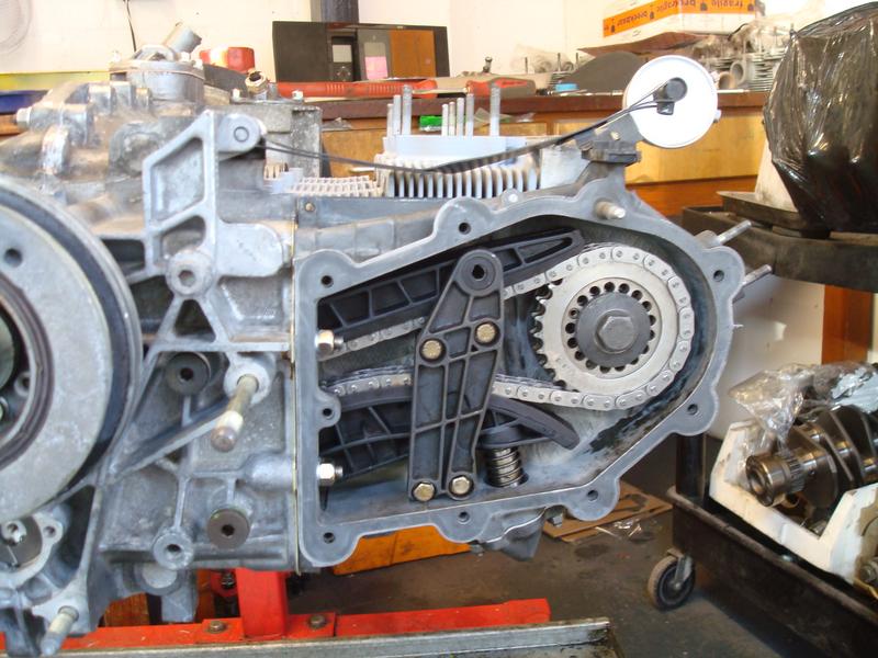
Here is a shot of the most complex part of the whole build, which Gus says sometimes the magic happens on the 2nd go, or you can be messing around for a while. We were messing around for a while.....
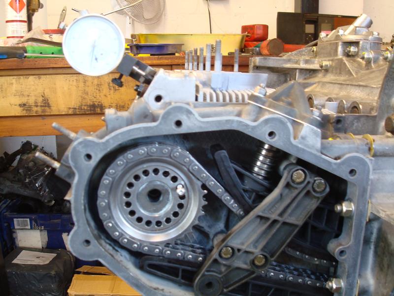
The gauge is secured to the cam carrier and has a needle which sits on the valve - it is effectively measuring lift. So at TDC, you are trying to achieve a precisely determined lift (so number 1 is firing exactly at TDC). Then repeat for number 4, though the order does not matter. I can't quite remember the numbers, but I think our target was 1.7mm lift at TDC (plus or minus 0.1mm)!!
To adjust it you can see a small pin with an M5 bolt in it - you effectively pull this pin in and out and into a different hole to adjust your position until you arrive at the factory tolerance. The problem is that if you are close, pulling the pin out can make the cam jump (or really slip) so your 1.7mm becomes 0.8mm, which then translates as nowhere near TDC when you achieve the 1.7mm you need. Following?
The next issue is that the pin will only fit in one hole perfectly at any time, so you need to create slip between the wheel and the cam to get your target hole to line up. Essentially we had slip when we didn't need it, then grip when we needed slip.....
Luckily, through Angus's experience in sensing by the relative position of where we were on lift vs TDC he manage to estimate where we needed to be, and after a few goes we got it. The second bank, by contrast, was achieved on the 2nd attempt in about 10 mins flat.
So there is cam timing in a nutshell. Frustrating, but super crucial for a good running engine. It can be influenced by wear in the sprockets, and we ended up towards the high end of the tolerance on both banks.
BTW - for those that do / have build engines I won't be offended if you point out any errors / provide correct terminology. This was the first time I have ever seen one be put together, so luckily there was an expert in the room!
Glad it's coming together
No major errors apart from you'll probably need to do your timing again as you'll need a tensioner tool.
964s still use the Vernier timing arrangement of earlier cars but require this tool as they use hydraulic tensioners that are different to the oil fed ones of the carreras that came before.
So in your timing chain sprocket you'll have a pin like your SC did and you'll have the woodruf key thrust washer shims and Vernier sprocket to set the Vernier timing. It's important to always put the tension back in the right side of the chain when doing 'slip' adjustments ie if you need to bring the tdc back go past tdc and then back to tdc then lock the cam up if in spec
For stock cams 1.7mm is not right think it's 1.25mm on overlap.
Ie tdc 1 firing lift on intake valve 4 @1.25mm
You can do the parallel running without the chains and it makes it easier before you put the Woodruff's in. Be sure to push the cams back with a light tap and the intermediate shaft onto its thrust bearing.
The later 993 engines changed to fixed timing and sprocket wheels that are purely held in place by friction on the camshaft(no woodruf keys pins or failsafe). This was because of the hydraulic tappets that set the clearance automatically and for simplicity. I always give the option to revert back to the old system certainly on rss and track cars .
That large viton o ring on the camshaft oil seal is best to have loctite574 to ease it in as the magnesium cam chain housings tend to have pitted sealing faces and can become porous.
Not sure if you did , but given the errors in the previous build you can remove the plug in the intermediate shaft and flush out all the crap in the oil galleries. It's also wise to separate the oil pump and check for scoring to the pump housing then reassemble.
Did you remove the pressure control and relief valves in the case to check their operation?
The washers are wrong in the tensioners and the cam boxes but I'm just being picky. They should be aluminium form A M6 and M8 .
Ps this is just how I do it there are other ways.
Good luck with the rest
Dave
Re: 964 C2 - Rolling Resto
Posted: Wed Jun 05, 2019 9:29 pm
by Bigfoot
Great thread! Wish my engine rebuild was only a couple of days

Always good to have guys with such a breadth of knowledge watching over you too to keep you right

Re: 964 C2 - Rolling Resto
Posted: Sat Aug 10, 2019 11:13 am
by rhd racer
So, it's been a while and my plans to buy more petrol than diesel have not exactly been achieved, but as it turns out I think on balance it has turned out for the best.
So, rewinding back to the engine build, the planned fitting weekend did not happen due to Gus and I both being dragged in different directions with family / work stuff. When trying to get a time in the diary to build it up and fit, it became apparent that we could not coordinate a weekend for about 2 months. The problem being largely that our race commitments just clashed everywhere, and he supports some customer cars which absorb other weekends too. So, with that in mind, I agreed to collect the car and get on with the other jobs on the list in the evenings, and then the time was not 'lost' completely and the project would continue to move forwards.
As it turned out, on going down to his workshop to collect the car, I could not get in the yard because a Boxster had turned up unexpectedly on a trailer for an engine from Ibiza. Yep, you couldn't make it up, so Gus was grateful of the space moving my car created.
Anyhow, back home for the first time since purchase!

The first job obviously being to give the car another jet wash in the engine bay...

And then into the 'working bay' in the garage
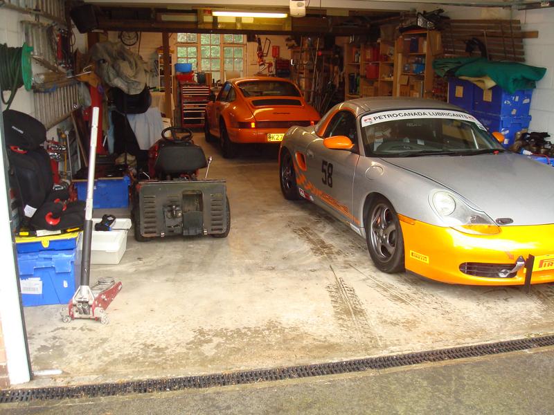
Where I obviously had to do a 'fitting' of the children to see if my dastardly plan for an occasional family vehicle was going to work, or if I had completely duped my wife....

Tick!
Re: 964 C2 - Rolling Resto
Posted: Sat Aug 10, 2019 11:21 am
by rhd racer
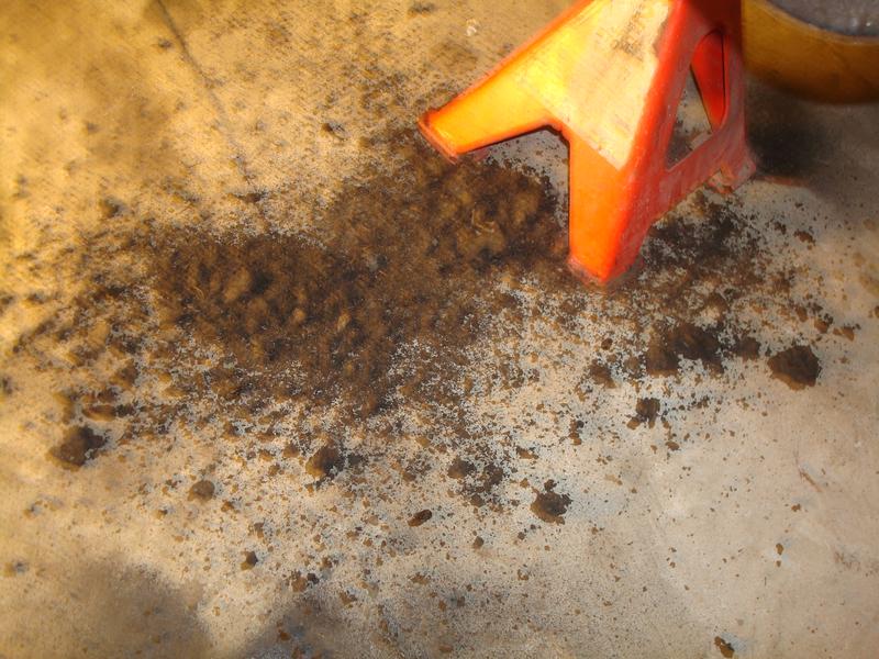
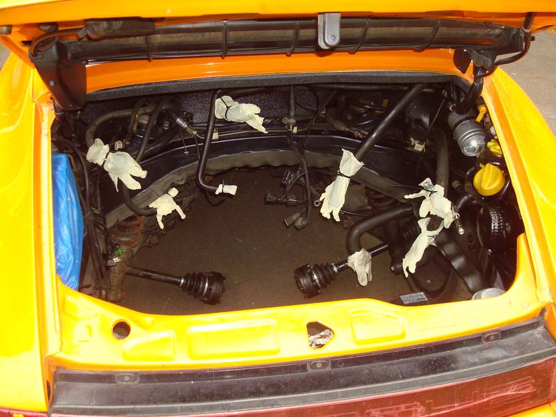
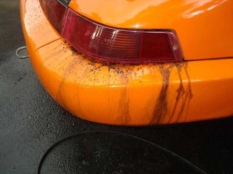
Now what I was struggling with was just how much oil there was. We had already jet washed once, and it just kept coming and coming. Turns out everything is completely caked, and the clean up to the standard I wanted simply would not have been possible with the engine in.....
Note the rear light covers in the inner wings are FUBARed, perhaps an indication of how well the rear wings were repaired.
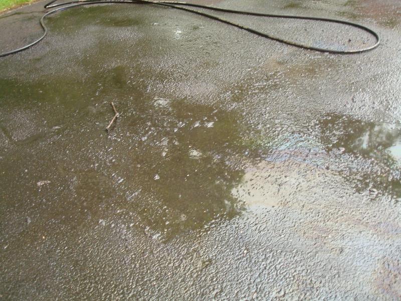
It was everywhere. After jet washing inside the rear wheel arch...
Next job will be jet washing the drive then...
Re: 964 C2 - Rolling Resto
Posted: Sat Aug 10, 2019 11:38 am
by rhd racer
So, on with the strip down
Rear coilovers off
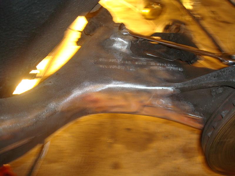
Learning about the good engineering of the 964 as I go, noticing all the little bits of rubber seal put on seams to prevent chaffing etc from the fuel lines. All a considerable step forwards from the older generation stuff I am used to working on (and in fact the Boxster too!). I think the 964/993 era sat nicely in an era where cost was not the only consideration.
That said, I will find some bits later in the strip down very reminiscent of the poor Boxster build quality, but will come back to that
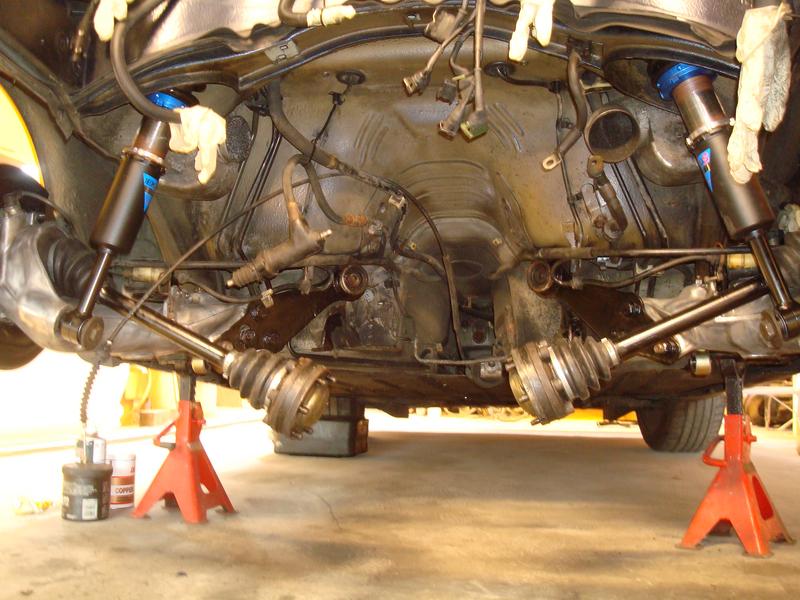
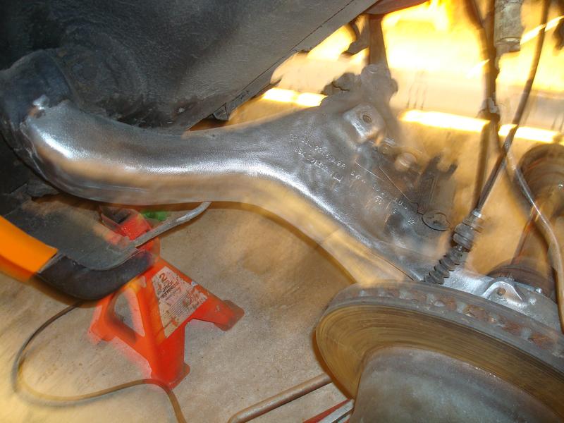
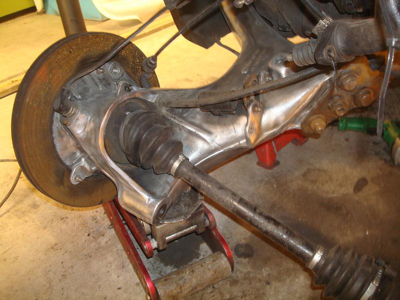
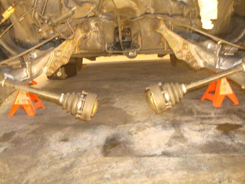
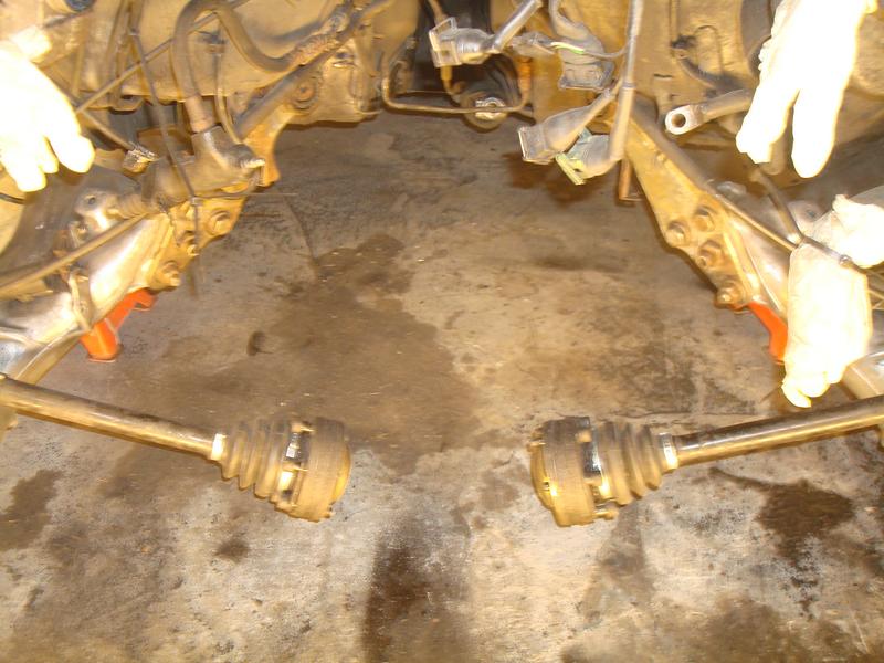
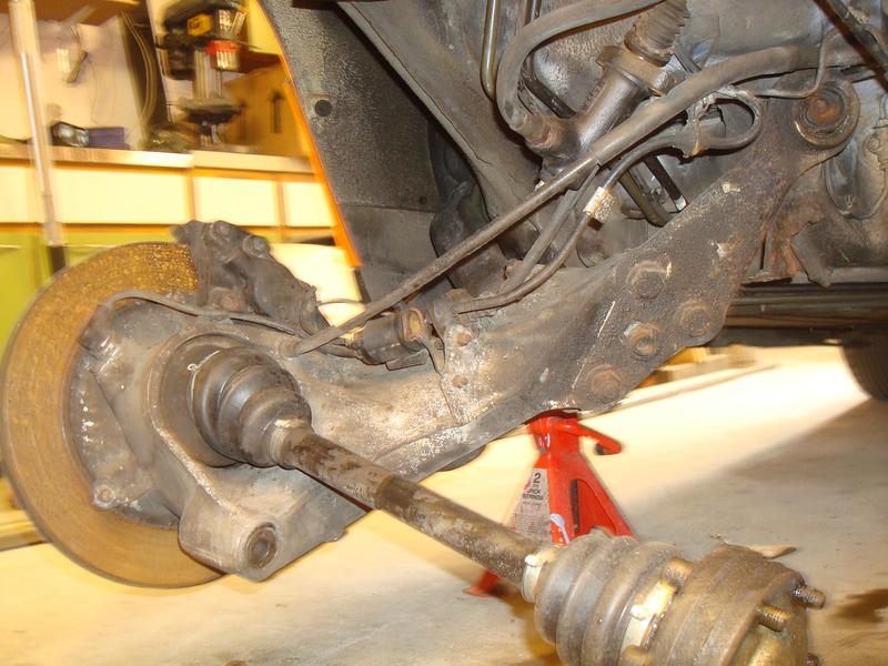
Now able to drop the trailing arms and see what I am working with
The view up the tunnel, which again not having the engine and box will prove useful later...
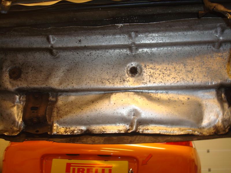
The rear heatshield has had a life, but I will work that back into shape later unless I can find a nice straight second hand one
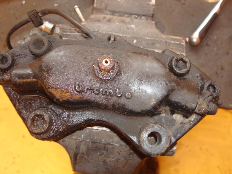
Then a lesson for me in Porsche design back in the day. I was struggling to get anything on the brake caliper allen bolts, so resorted to some home engineering...
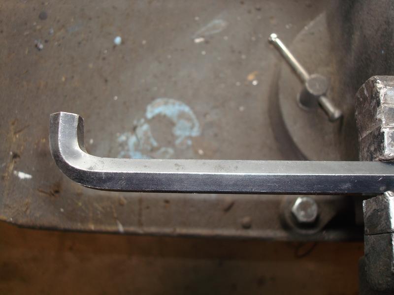
That did not work, those calipers were well and truly on there. So whilst scratching my head I had a good look round and was given a lesson by Porsche engineers. They had thought of this already....
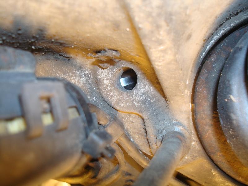
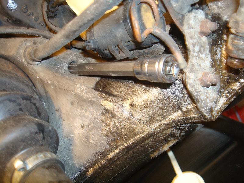
They were still blood tight mind, and I had to use a lever bar extension to loosen. One bolt was absolutely mullered, and I was really lucky to get it out. I used a splined hex key, and a 4 foot bar and it just grabbed it enough to loosen. Phew...
Re: 964 C2 - Rolling Resto
Posted: Sat Aug 10, 2019 11:49 am
by rhd racer
So, onto the brake pipes. A nice easy job.
Well, no. I had only bought rubbers, because they were perished, so that meant braking the joints with the solid lines either side, which were actually in good nick and passed inspection. I have done loads of brake work on the race cars over the years so know how easily a simple job can turn to rat poo, so have a range of brake spanners that grip all bar one side of the hex, so you don't round off the unions. Well, it turns out that my lines had all turned to chocolate, and despite using this spanner they all rounded off. So, the only way to split them was to cut each one off with a hack saw, put it on the bench and split the unions in a vice with a socket set.
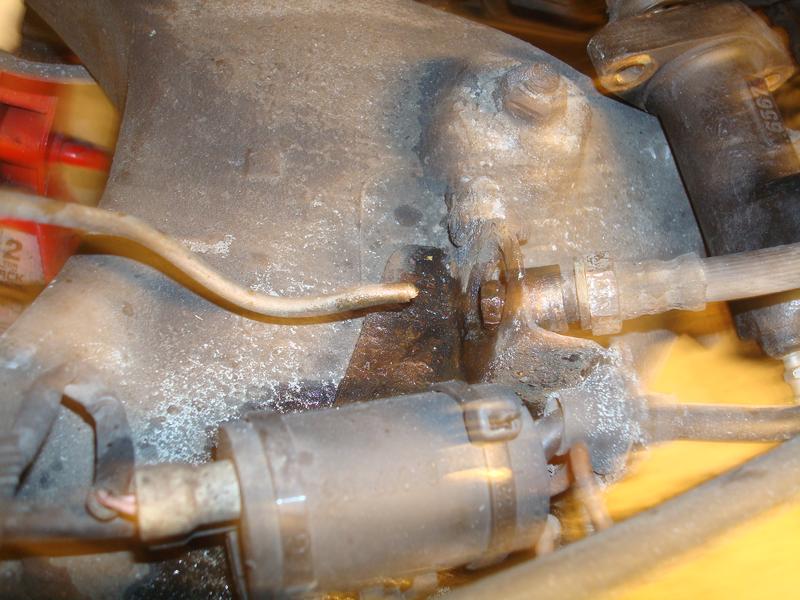
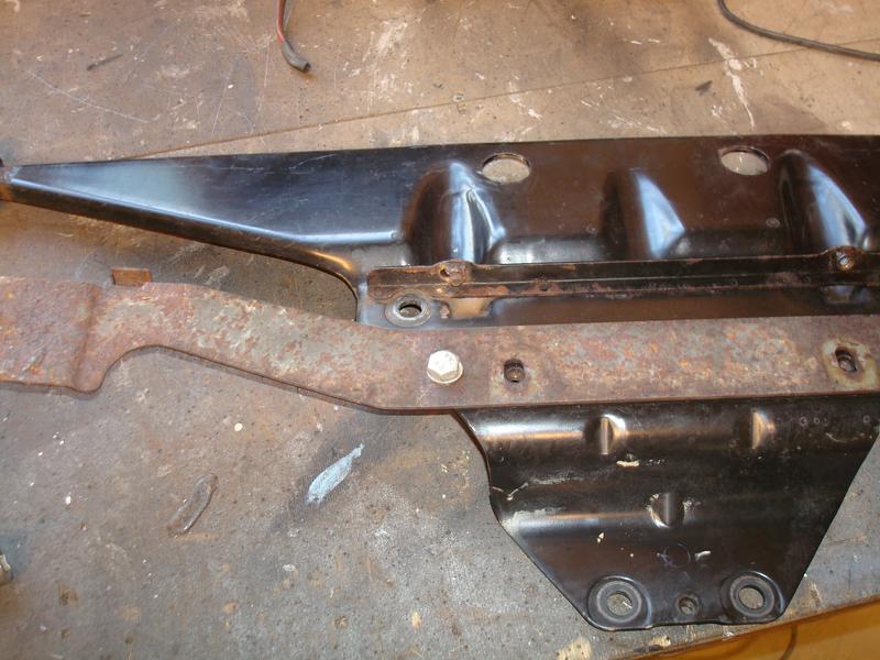
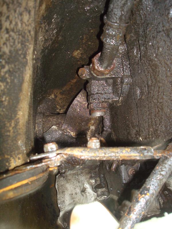
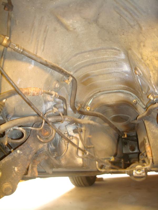
So, I'm replacing the hard lines too then. Another win for not having the engine and box in, with junctions like this up the side of the box
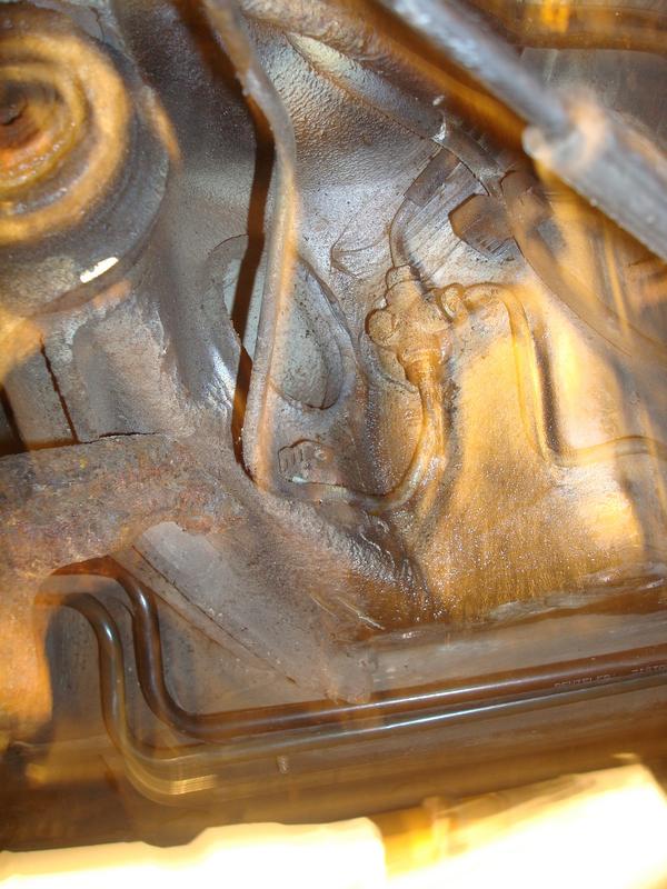
Now you could well ask why I would take such care splitting the lines. Well, they are pretty expensive from Porsche, and I have a brake pipe flaring tool, and probably enough M10x1.0 connectors in stock to make my own lines - I just needed to buy another roll of copper nickel brake pipe. In having a template for every line (except the length of each union), I would have a set of templates to make them all up to.
You might ask why I would do this
Re: 964 C2 - Rolling Resto
Posted: Sat Aug 10, 2019 12:08 pm
by rhd racer
Re: 964 C2 - Rolling Resto
Posted: Sat Aug 10, 2019 12:11 pm
by rhd racer
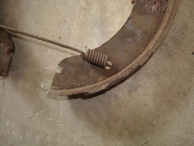
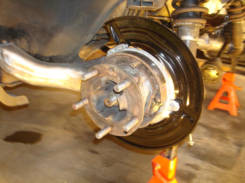
And then as a matter of course I removed the rear discs and removed, greased and reassembled the handbrake shoe assemblies
A bit of delamination of one rear shoe but all pretty good really
Re: 964 C2 - Rolling Resto
Posted: Sat Aug 10, 2019 4:18 pm
by rhd racer
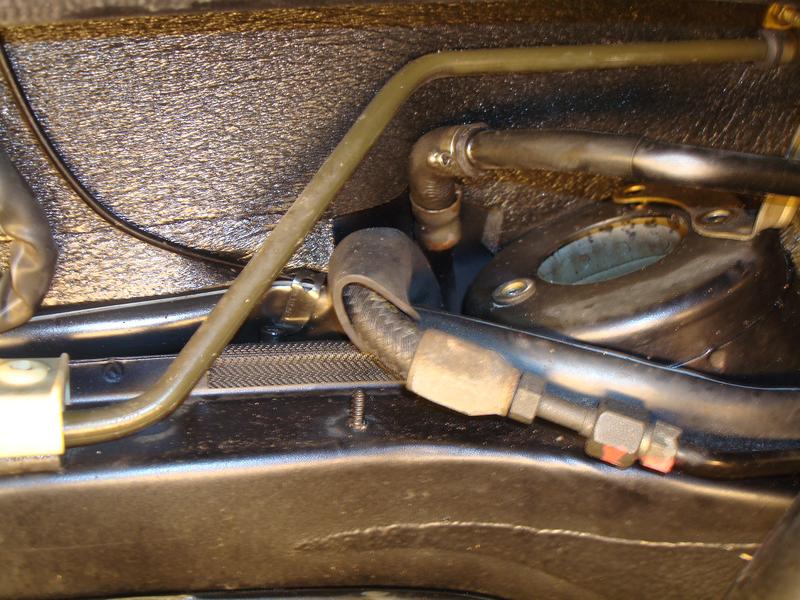
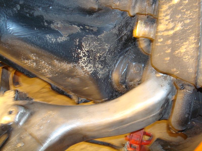
So whilst working under the rear arches one thing kept grating on me. I can't really understand why on the n/s rear arch, there is a plastic liner in the arch protecting seemingly very little. However, on the business side, the o/s rear, there is nothing. You have the oil tank completely exposed, the hard oil line and the back of the filter housing, all ready to collect anything flying around in the wheel arch. I have since does some research and it appears the only 964 model to have any protection in there is the Turbo, but at £300 for the plastic liner designed for a wide-body, it was too much for me to take a punt. So a bit later, I will probably cut up an old welly and make something.
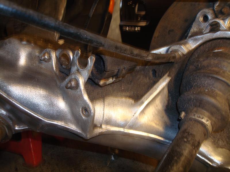
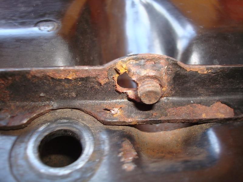
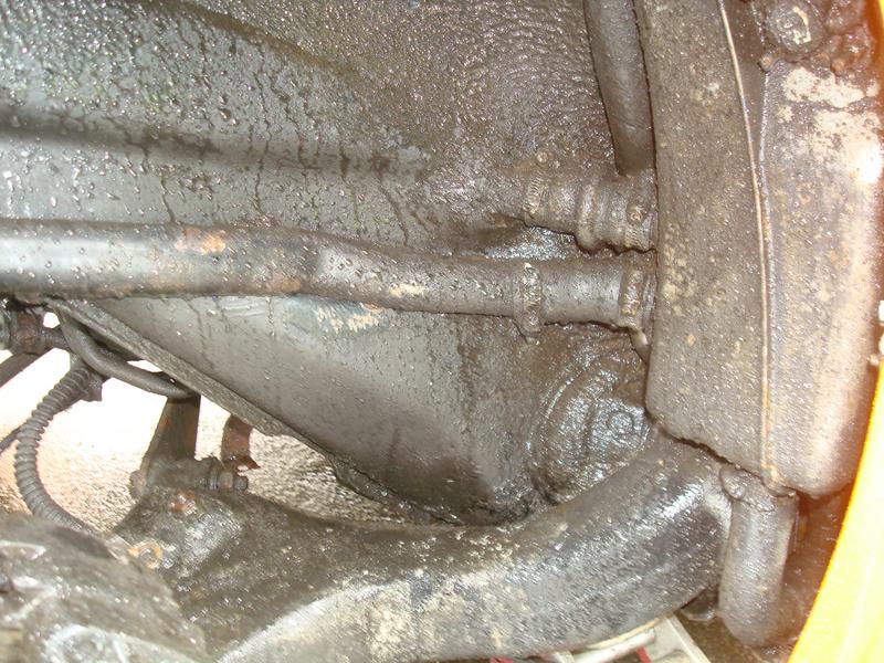
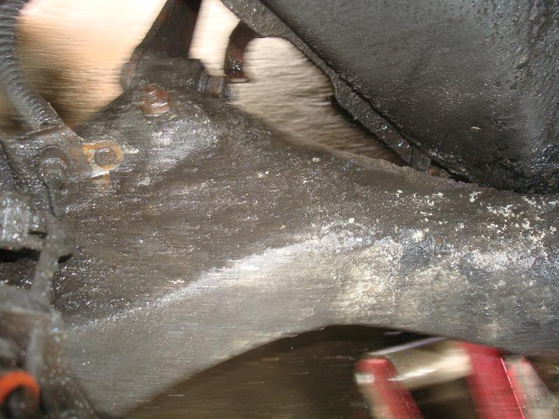
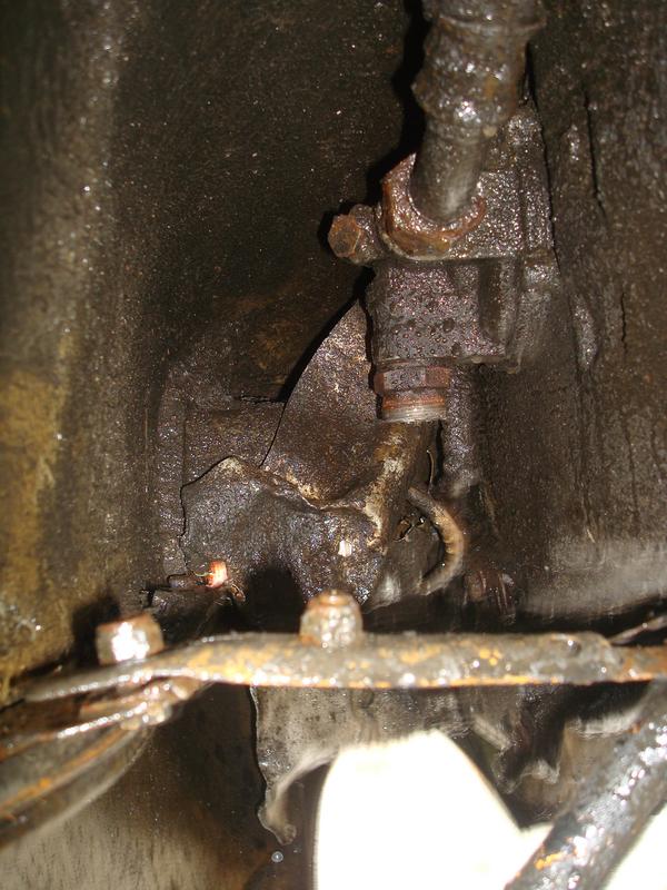
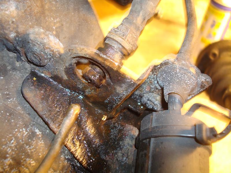
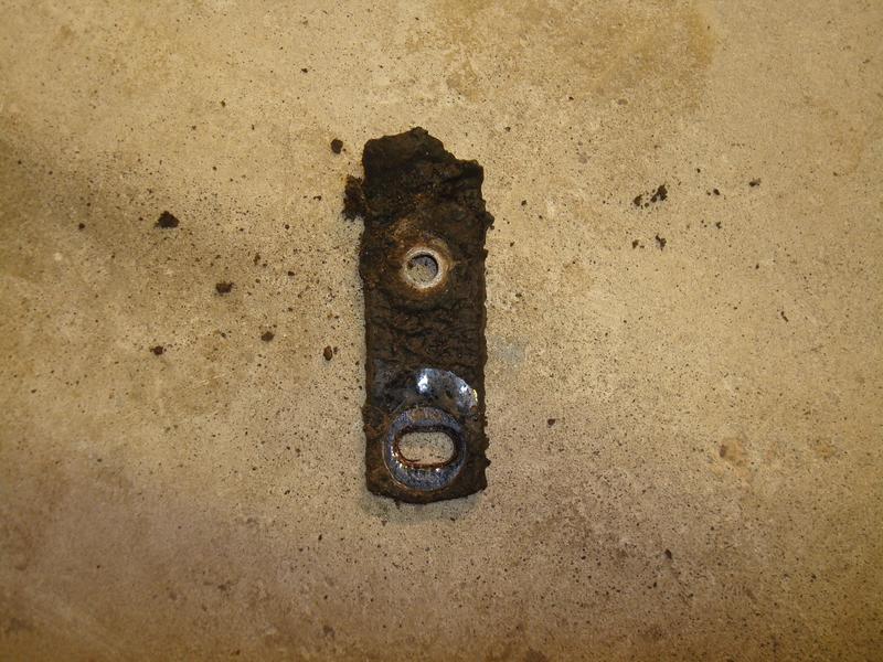
Anyhow, for now the hard oil line was looking a bit crusty. Aside from the obvious oil, despite numerous degrease and jet wash cycles, it had a patch of rust so I thought I would take it off, clean up, rust treat and paint.
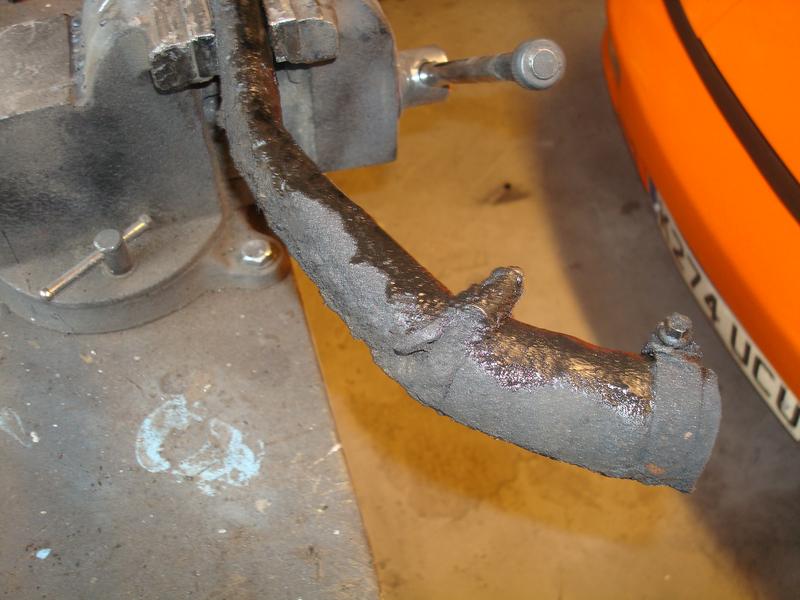
As you can see, pretty ropey.
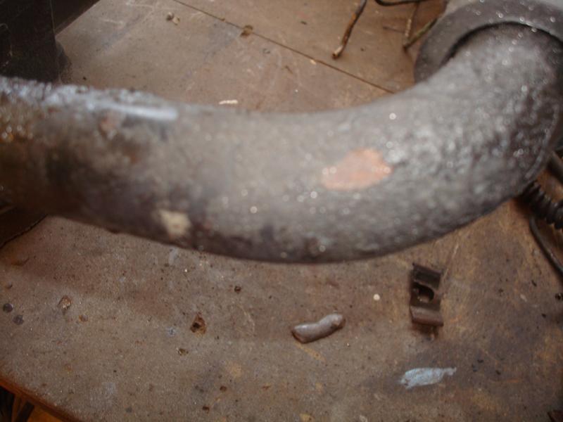
So I carefully cleaned it up and another dirty secret was revealed...
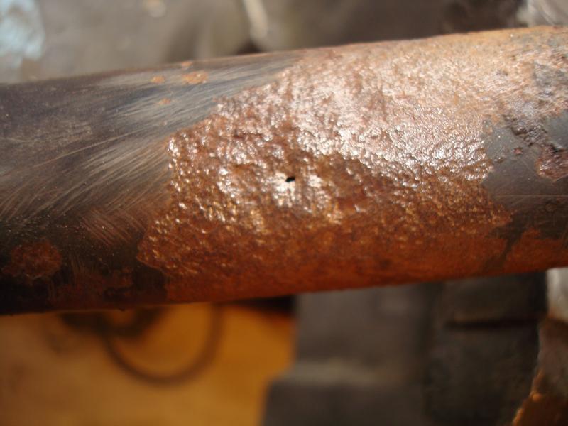
So now I could understand how there was so much oil everywhere, and continue the clean up whilst a new pipe was ordered
Re: 964 C2 - Rolling Resto
Posted: Sat Aug 10, 2019 4:41 pm
by rhd racer
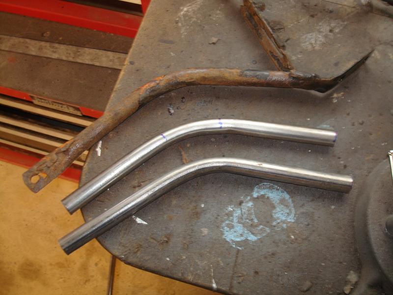
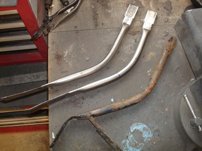
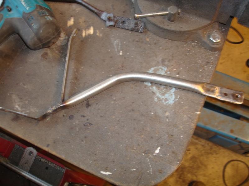
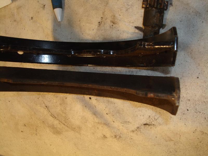
Rooting around in the rear arches I noticed that there was only 1 rear stay holding it on, and to be honest that was a week or two of enthusiast driving from rusting in two also. So I set about using it as a template to make a new pair, plus two new shorter ones for further back in the arch.
These are £100 for a set, but I made these up in about 2 hours with bits from my scrap metal bin.
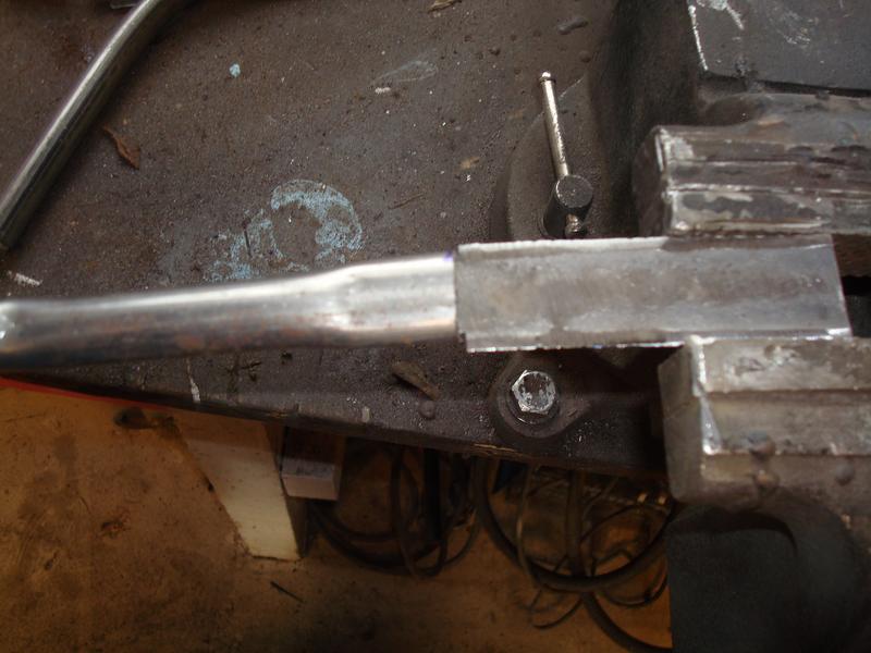
The original, and two bits of tube formed to the same radius...
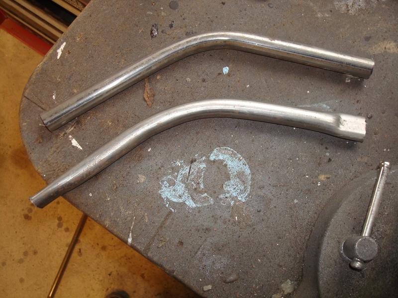
Then flattening the ends per the original, note they are flattened at 90 degrees to each other end to end
Then cut a small strip of steel as the starting point for the mount
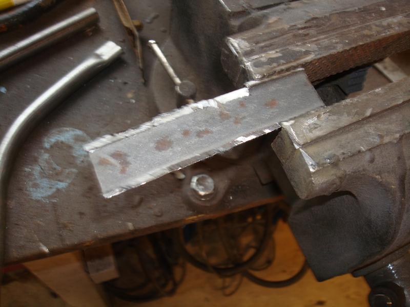
And cutting into a shape which will then slide into the flattened end of the round section (which seemed to be how they were made originally)
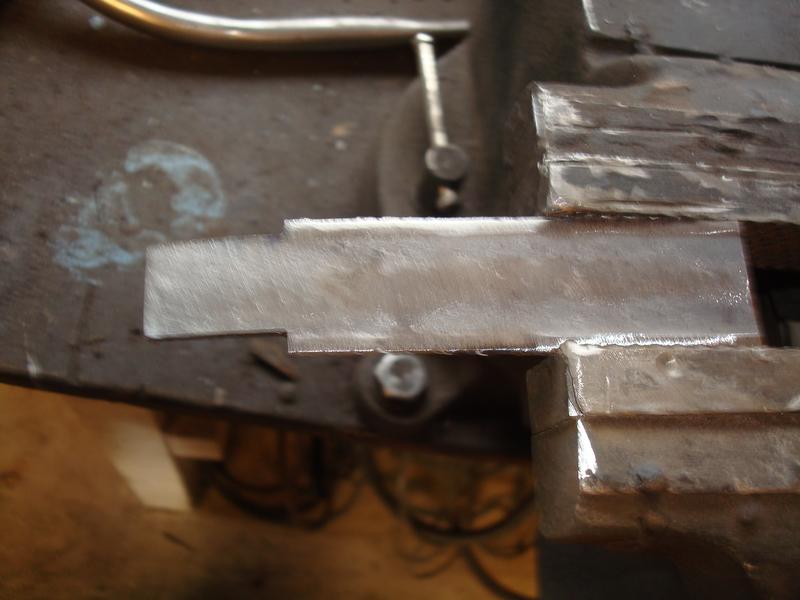
Like so
Both done, against the original
Then adding the additional cross brace per the original, and welding up
The original sections was still attached to the bumper!!
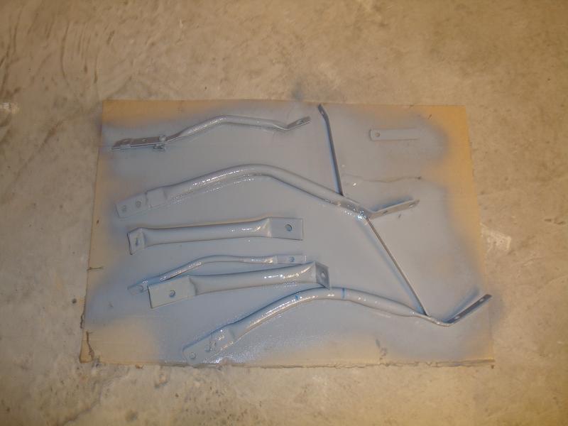
In primer
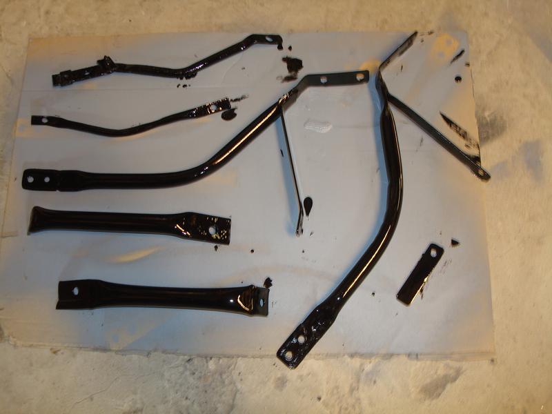
And topcoat. Job done. I love jobs like this, turning old rubbish that most would throw away into something with a purpose. That's how I justify being a hoarder to my wife!
Re: 964 C2 - Rolling Resto
Posted: Sat Aug 10, 2019 4:53 pm
by rhd racer
So back to the brakes.
On the back of my doing things once and doing them properly strategy, I ordered some new brake shoes having found the delamination on the edge of one of them. Euro sent these, which bizarrely used a pattern which was too thick to use, as none of the cross braces or the cable mounting widgets would fit. The below shows the difference
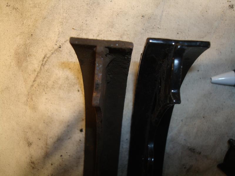
I could have ground these down at the appropriate point, but it didn't seem right to spend £50 odd on new parts and then spend an hour messing about to get them to fit. To be fair to Euor, they took them back and refunded without a quibble.
So I looked again at the old ones and decided to reuse them, as to be honest they probably have more meat on them than I will use in my lifetime, as I don't intend to raz around car parks doing handbrake turns like Ken Block!
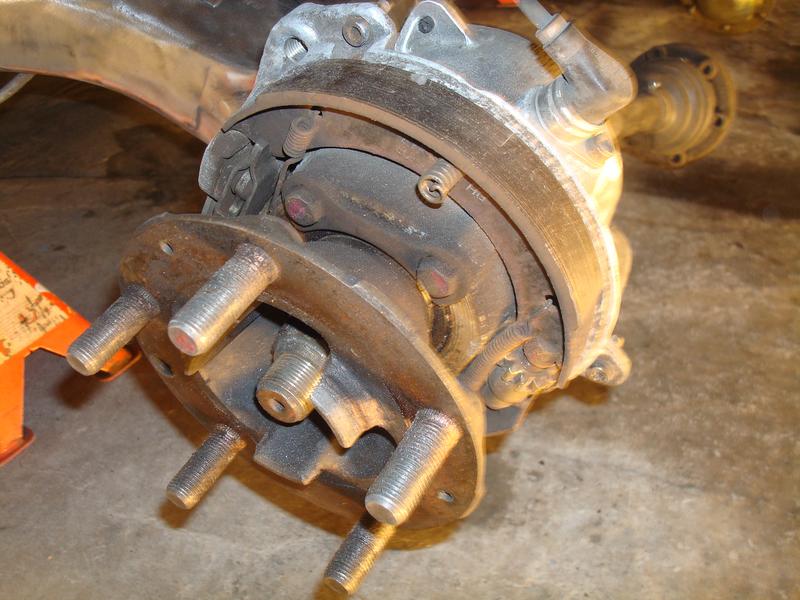
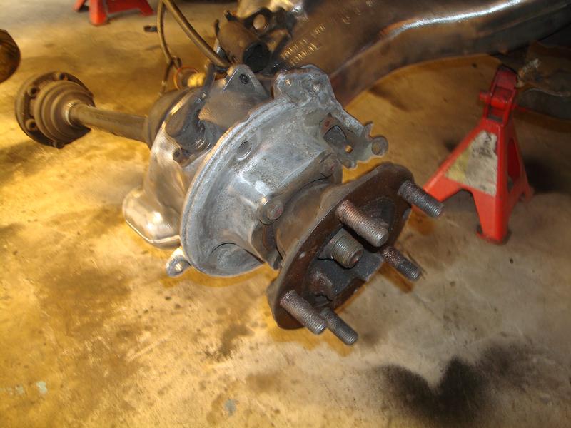
So I fitted the new backing plates (note I had loose fitted the rear coilovers again so I could roll the car out of the garage for a further jet wash under there...
And discs
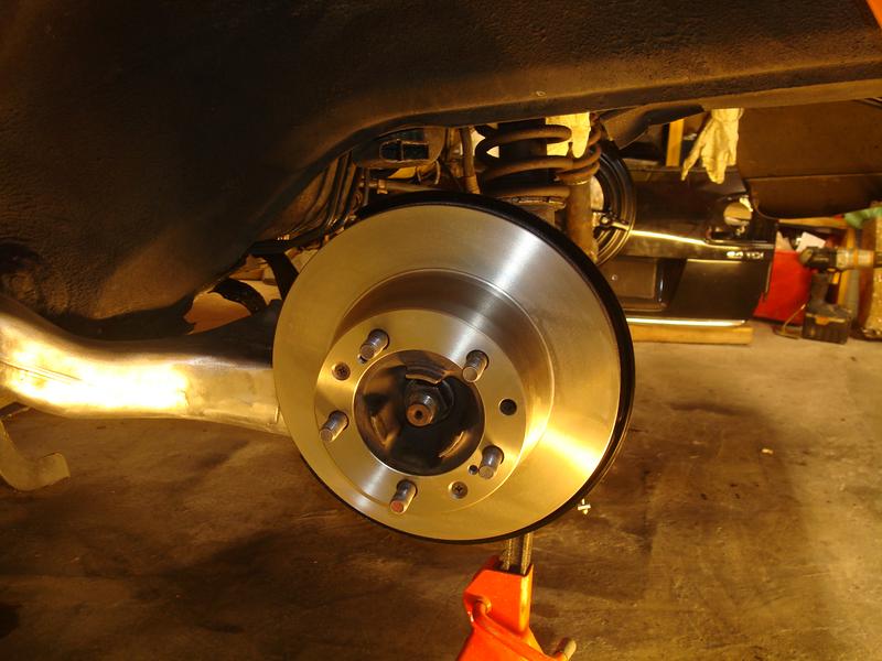
And then because I hate it when you put new discs on and the bell section corrodes, I painted them for good measure

Re: 964 C2 - Rolling Resto
Posted: Sat Aug 10, 2019 5:04 pm
by rhd racer
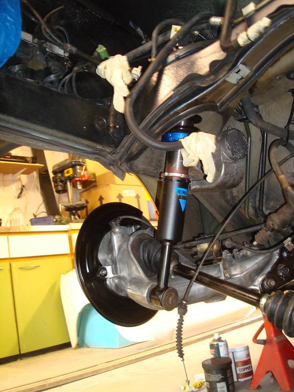
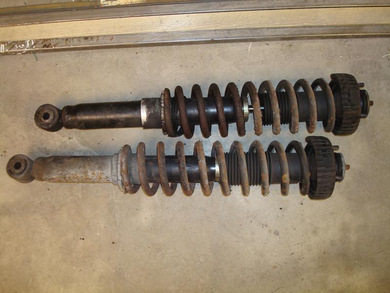
So, I was finally ready to fit the rear coilovers.
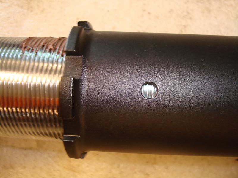
An odd arrangement to be honest, the likes of which I have not seen before, they have adjustable platforms and adjustable feet, so you have two entirely independant levels of adjustment and therefore would probably be able to get the thing on the ground. Those days are over for me (almost) so I set the lower at the longest (highest setting) as depicted by this hole in the lower assembly which I guess ensures that you always have enough thread in the unit.
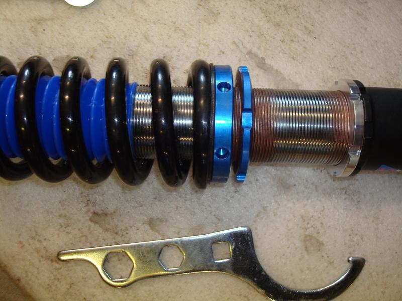
I then set the preload on the springs
And finally fitted to the car. You will see I have also rust treated and painted various bits too.