Page 24 of 81
Posted: Sat May 09, 2009 6:21 pm
by Mike
sladey wrote: any special spec on the rods
Sorry Mark but the rods are pretty standard Carillo's, just their run of the mill straight 'H' beam profile for maximum strength, but ordered with their Carr (mulitphase) bolts which are a bit special in that they have a UTS of 285,000 (ultimate tensile strength)
Thanks for asking

Posted: Sat May 09, 2009 6:40 pm
by Mike
As I'm bored waiting for the build to start, I've photographed another nice RSR part, the the lightweight crank pulley. It's specially made in a single forging, and as a word of warning you can't use a standard one and drill out the holes as has been suggested on another forum, as it's pieces welded together and will break up, apparently.

Posted: Sat May 09, 2009 8:08 pm
by brembo
When does engine build start Mike?Must be pretty frustrating having all parts and nothing happening.
Dougie
Posted: Sun May 10, 2009 11:53 am
by Mike
Dougie, hoping for the bottom end to go together shortly, but due to Neil the engine builders 'adventure' this summer I don't expect much to get done until September time.
As for what Neil's up to, I'll start a thread in general chat.
Mike
Posted: Tue May 26, 2009 1:10 pm
by Mike
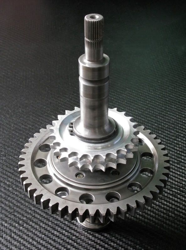
Apologies for a picture of another 'bit' but this is the latest part to go together, the inter-gear shaft. It's a bit special in that the chain drive gears
are lightweight aluminium racing ones, and the main drive gear is a lightweight straight cut version.
Posted: Sun Oct 11, 2009 6:11 pm
by Mike
Well, after a summer pursuing other commitments, traveling and spending time with the family, back on track with the car for the start of the engine build!
Just spent the last week at BS Motorsport helping put the motor together, we've decided to do a full competition RSR engine and the level of Neil's attention to detail is incredible, the tolerances he works to are all so small and his patience with measurements has to be seen to be believed. We were doing 14/15 hour days all week, for a full competition build he quotes 160 hours in total and I can see now where all the time go's!
So to pick up where we left off, the carillo rods went onto the 70.4 crank beautifully confirming it's great standard/standard condition, we only had it polished and then balanced with the flywheel, clutch and bearings.

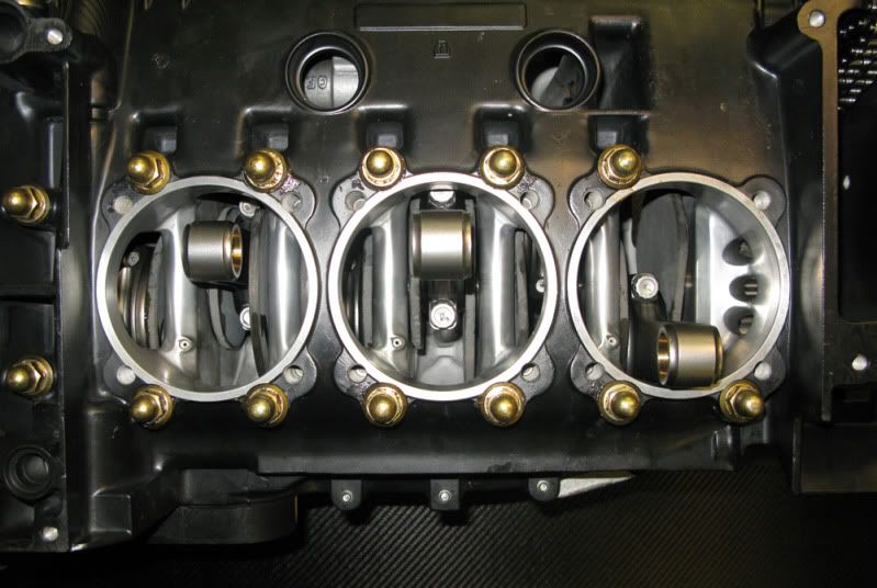
The picture below shows the shuffle pinned cases with the crank in with the carillo rods, the straight cut and lightweight intergears and ali cam gears in situ with the high flow GT3 oil pump with a modified scavenge pipe and strainer so as to keep a flat early sump plate, like an original RSR. Even the sleeve which connects the intergear to the oil pump is modified, instead of the usual circlips to keep it in place which are unreliable and can break in race engines, the sleeve is pinned inside to stop it from sliding, no nasty bits to fall off!
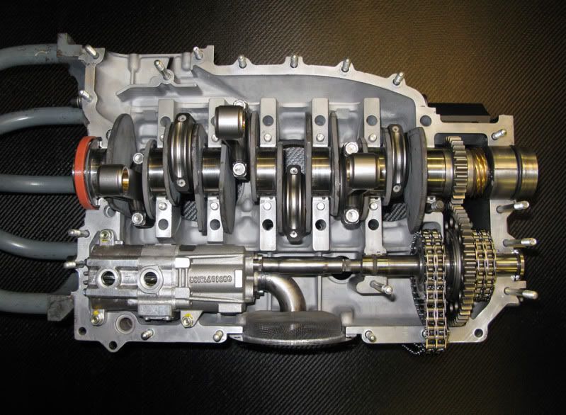
Cases go together and the final view of the windage work on gas flowing and polishing.
Posted: Sun Oct 11, 2009 6:57 pm
by Mike
After originally buying a set of Mahle barrels and RSR pistons, when tested they didn't come near to the 10.3:1 compression ratio the factory 'werks' cars ran, so as Neil insisted on forged pistons instead of CNC'ed billet like JE's, we went with Wossner who are a German Motorsport supplier. Porsche themselves use their pistons for some of the factory race engines apparently. They claim 10.5:1 and when we cc'ed them with my heads and ran the figures through the computer we got 10.1 but more of that later.
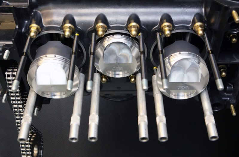
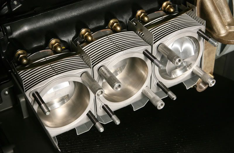
The Mahle barrels go on with the RSR 'tinware' between, RSR cos it's aluminum, and in this case anodised

Right is a temporary race filter housing, the right one arrives soon. This replaces the engine oil cooler the road cars have.
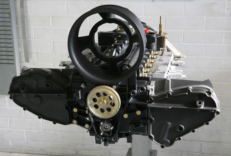
Couldn't resist resting on the chain boxes for the oil fed cams and fan housing at this stage, and you can see the bracket for the mfi pump support bracket top right sticking up.
Posted: Sun Oct 11, 2009 7:50 pm
by 210bhp
Mike
Beautiful, beautiful.....
What were the various surface sealants used on the case halves, saddles etc . Just nice to know (asking for Brendan

)?
Regards
Mike
Posted: Sun Oct 11, 2009 10:59 pm
by Mike
210bhp wrote:
What were the various surface sealants used on the case halves, saddles etc . Just nice to know (asking for Brendan
)?
Mike
Mike, I'll find out what the orangey squidgy stuff was and get back to you!
Posted: Sun Oct 11, 2009 11:00 pm
by Viv_Surby
Looks stunning Mike.....glad to see works progressing again

Posted: Sun Oct 11, 2009 11:27 pm
by brembo
Brilliant Mike,you should write a book about this car

Dougie
Posted: Sun Oct 11, 2009 11:36 pm
by Mike
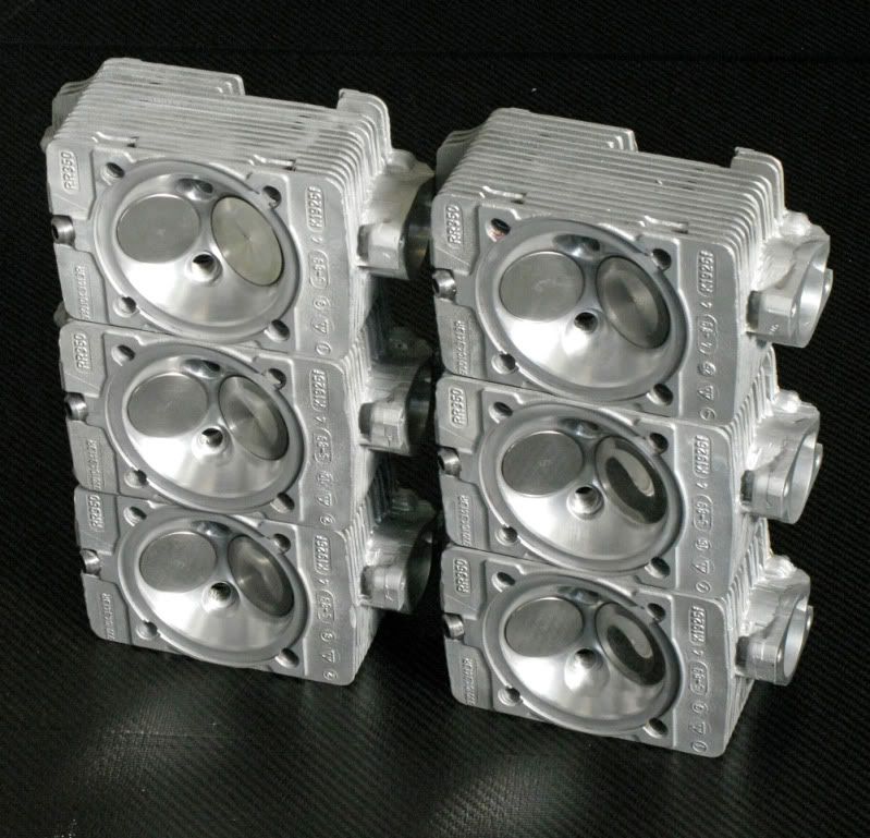
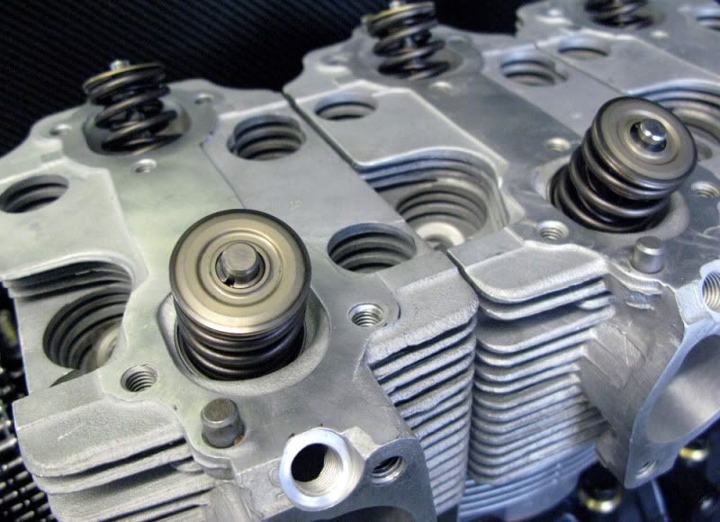
A lot of work has gone into the heads over the past 6 months, from the original machining of decking and twin plugging, to then the fitting of seats and guides and the porting and polishing. It's been a long journey to get them to the stage of finally fitting the valves.
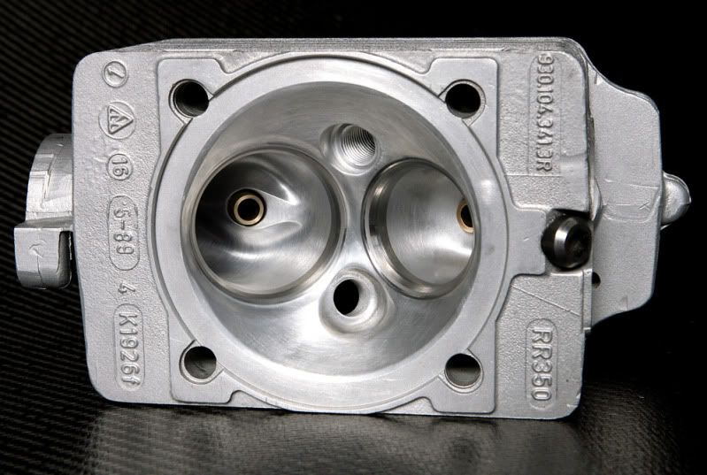
The man who did all the work is a very well respected head engineer now in his seventies who has worked in the past with Formula 1 teams and knows Porsche heads inside out. He has a mass of data from all his past efforts and charts and graphs galore mapping the various permutations, I didn't realise how much of a 'black art' all this is, but after going on his flow meter for the final time and doing the calculations he pronounced them the best flowing heads he's ever done!
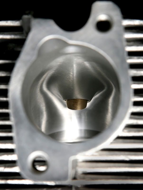
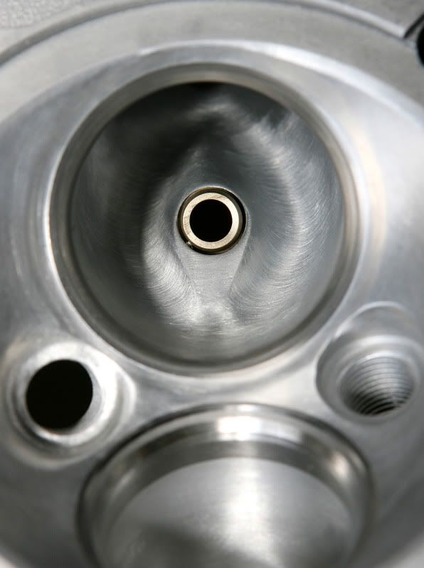
Maybe that's something to do with the fact they have the correct RSR porting of 43mm both inlet and exhaust.
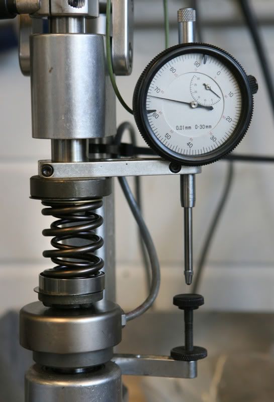
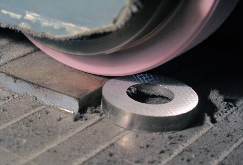
Fitting the valves was another example of the accuracy used doing this kind of stuff. Using Schrick racing springs with titanium collars you have to measure their individual heights given the maximum and minimum lift required, then machine the spring seats to the nearest couple of thou to give you the optimum operating timing and balance between them all. This involved about 12 hours between the micrometer and the machining lathe then back again, measure then machine and again, and again to get the right sizes, so about a hour each one then!
Posted: Mon Oct 12, 2009 7:33 am
by Highfield
Mike
It looks more like a work of art than an engine.
Great job.
Ian
Posted: Mon Oct 12, 2009 3:03 pm
by mrg3.6
Wow - those heads have an almost 'biological' feel to them

Great work.
Martin
Posted: Mon Oct 12, 2009 3:57 pm
by Mike
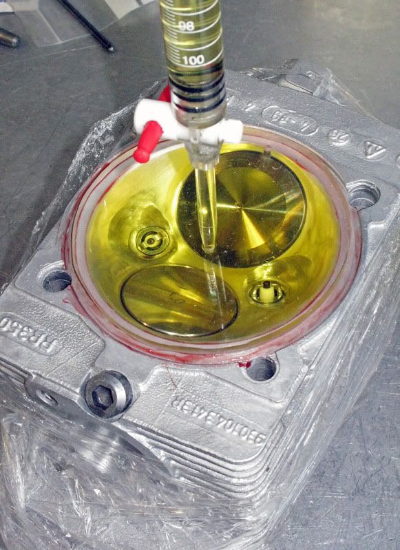
Now the valves are in, we can now properly cc the heads for the next stage which is to make sure they all have the same volume. This is done by placing a flat clear plate with a central hole as a filler and another at the top to let out the air, and then filling with fluid, in this case paraffin. This is a very controlled process to get right, with bubbles being a big problem.
Having then measured the volume in each head and seeing the discrepancies, you have to machine out small amounts of material from each spark plug pocket then clean it all out and set up the measuring system again. It still won't be right unless you are really lucky so you take out the fluid, clean it up, machine again, clean that up fill with fluid and measure again hoping it's right this time.
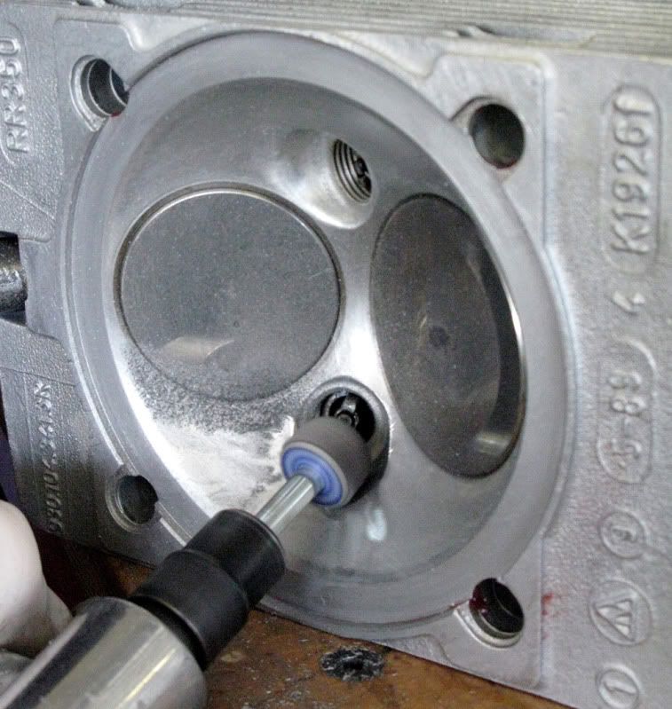
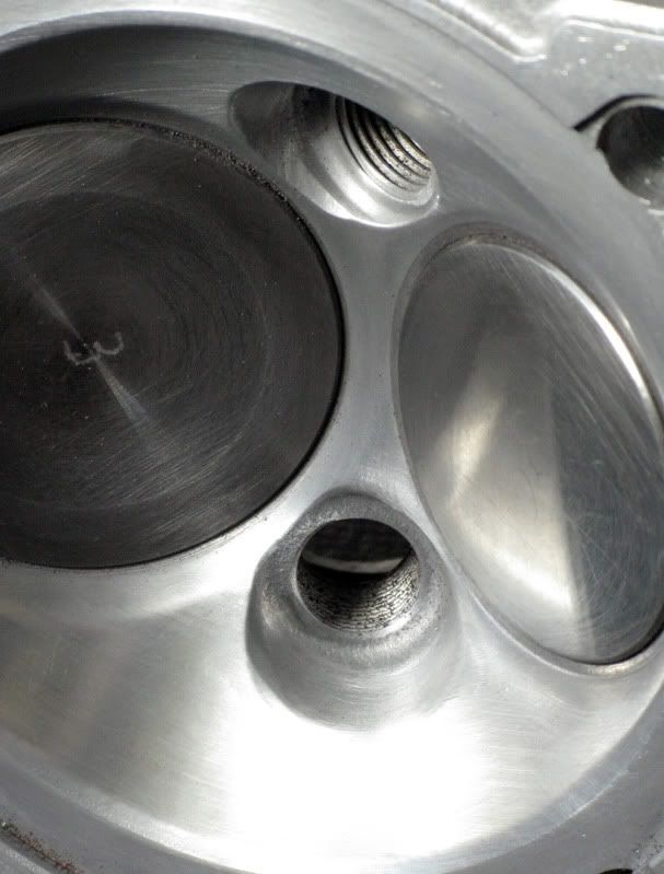
Then just the other 5 heads to do. You begin to realise how time consuming this all is and why a competition engine takes so many hours to build. We got the volumes to match in all heads to within .2 of a cc in the end which is pretty good I'm told. Note below the valves are numbered to the particular head, which is seen prior to cleaning.
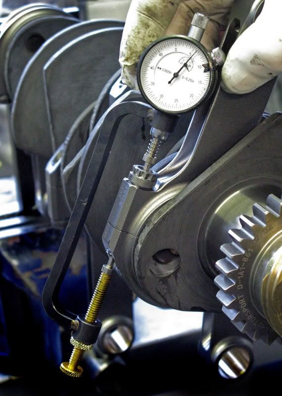
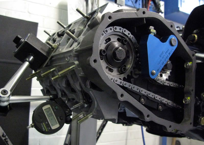
Another test before fitting the heads permanently, is the head to piston clearance and valve to piston clearance, again we had the computer predictions but have to confirm it physically. You have to fit up the cam and rocker and do the cam timing to bring the piston to tdc then use bits of plasticine, fit the head then torque it down. For the valve to piston clearance you set up a micrometer and measure the valve stem travel to work out the gap.
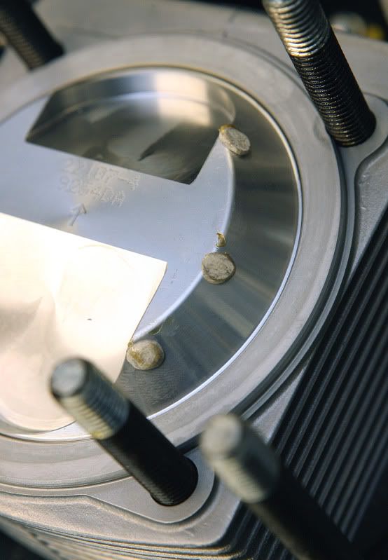
Plenty of gap for safety and as the pistons have deep pockets more than enough for even the occasional over rev
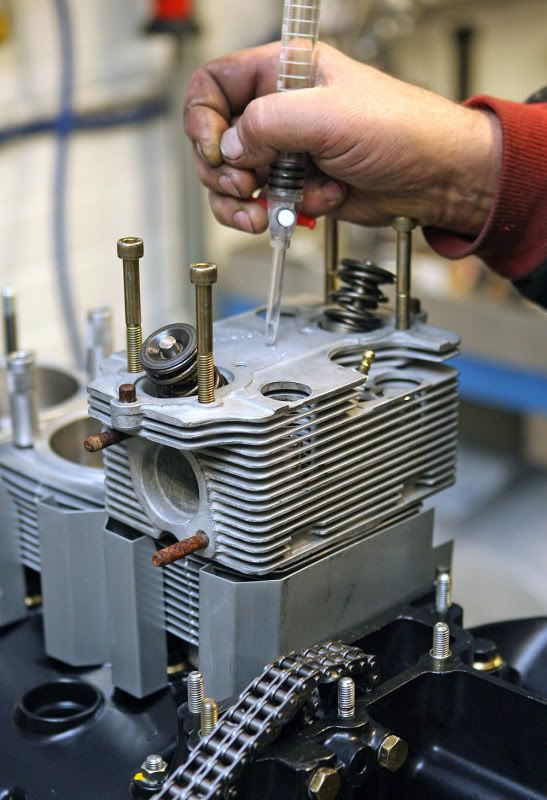
As I mentioned before the computer prediction for the compression ratio was 10.1:1 slightly lower than we hoped for, but it's not until you can physically test the head in situ that you come up with the true figure. The bench volume test as outlined earlier gave us a new better figure but to make sure we did two more tests. First using the twin plug head already torqued down we fitted in place of a spark plug a specially made one with a hollow centre to flow paraffin through, then measuring the fluid put in and rocking the engine to get out bubbles we got a new figure of 10.4:1. I was really pleased but it still wasn't accurate enough for Neil, the problem being you can't see in and therefore can't be sure you have all the bubbles out! He had a final test up his sleeve. He took off the twin plug head and fitted up a scrap head with a known volume which had a drilled hole dead centre through the top into it's chamber. Now pouring in the fluid, as it's a central hole gravity ensures the air rises to the top and out, giving now the most accurate figure you can get, and doing the calculations by hand it confirmed the 10.4:1
So now the heads were done and ready to go on.