Ok, I've been fiddling, here goes
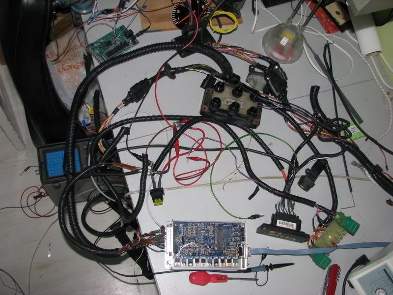
Here is the kit as I've set it up for testing. The Inlet Manifolds and TB are roughly where they would be on the engine.
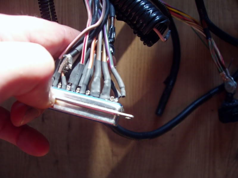
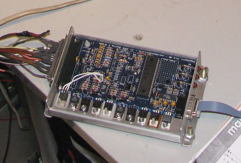
This is the Megasquirt itself, lid removed. I've still to tidy the soldering to the main connector. The white wires inside the box are the Beefed up F-IDLE circuit (Fast Idle)
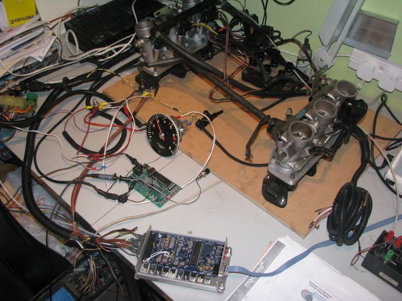
Here is the NS bank of TB's, fuel rail and injectors inboard. The TPS (Throttle position sensor) in the back corner of the engine bay.
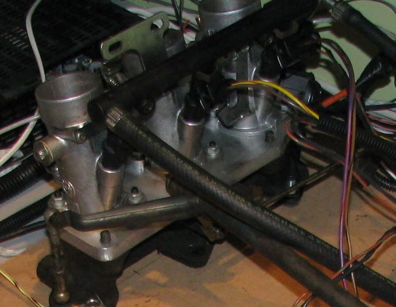
This kit is actually running in the photo, you can't tell but it is.
The circuit infront of the Tacho simulates the VR sensor and 36-1 toothed wheel that would be on the crank. The bottom LED is 500RPM led and the other LEDs show 1K rpm each so showing 3K rpm at the minute. Tweak the POT and the Rev counter follows!
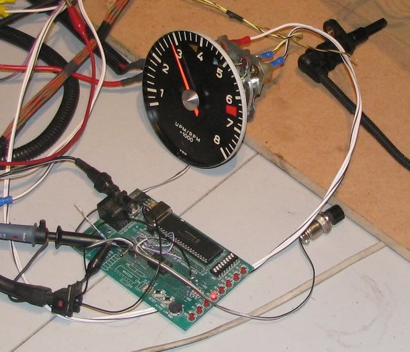
This circuit triggers the EDIS module (Coil pack is un plugged to prevent sparks from flying) which then feeds pulses to the Megasquirt.
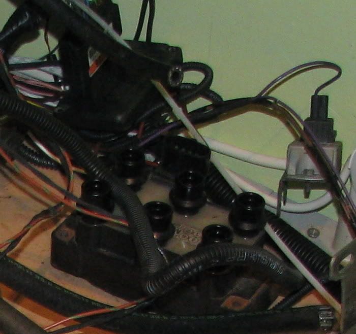
and away it goes, Injectors pulsing away. The Tacho trigger comes direct from the MS (I've had to change one resistor in the Tacho to get this to work, and the MS has a small transistor mod done to add additional drive for a tacho but I'm not too sure this was necessary but it does work.
I have The TPS, IAT (Inlet air temperature) and CHT (Cylinder Head Temperature) sensors all feeding back to the PC.
Oh, and here is the Relay block that sits next tot he fuse box up front
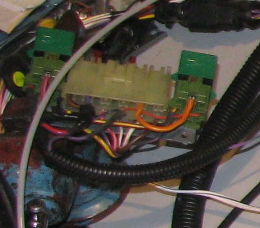
All really cool, and almost entirely using Gary71 wiring loom. So Gary, the work you did was all good

and your diagrams are spot on, thanks. Just a little tidying required.
I now need to think about how to adapt the throttle linkage, but following the way the Zeniths work is probably a good plan.
Cheers
Tim