

Meagsquirt EFI on a 2.2T - Real time data view with iPad
Moderators: hot66, impmad2000, Barry, Viv_Surby, Derek, Mike Usiskin
-
impmad2000
- I need to get out more!
- Posts: 3305
- Joined: Fri Nov 14, 2003 8:31 am
- Location: Leicester, a convenient mid point !
- Contact:
Gary,
Just been looking at the wiring. I think I've found your problem....
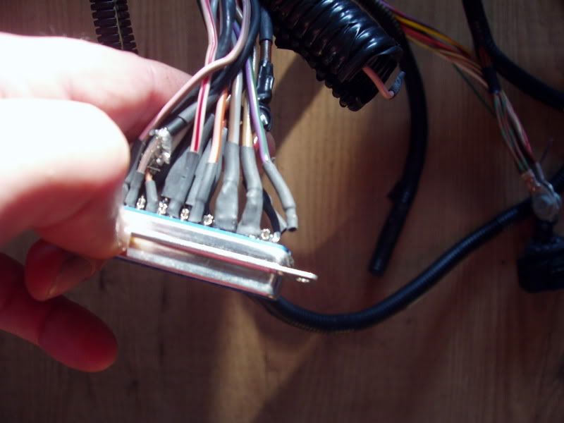
The Purple and green wire is the switched 12V and it just came off in my hand ! The MS would have reset like crazy, and the EDIS would have flicked from timed, to limp home at will !! I will double check the rest.
I know, you always did say that you didn't approve of the D-Type connectors on the Megasquirt !!
Cheers
Tim
Just been looking at the wiring. I think I've found your problem....
The Purple and green wire is the switched 12V and it just came off in my hand ! The MS would have reset like crazy, and the EDIS would have flicked from timed, to limp home at will !! I will double check the rest.
I know, you always did say that you didn't approve of the D-Type connectors on the Megasquirt !!
Cheers
Tim
Tim Bennett
RHD Targa 2.2T EFI, Triumph ITB's, EDIS and Megasquirt.
"Old enough to know what's right and young enough not to choose it"
#1153
RHD Targa 2.2T EFI, Triumph ITB's, EDIS and Megasquirt.
"Old enough to know what's right and young enough not to choose it"
#1153
-
impmad2000
- I need to get out more!
- Posts: 3305
- Joined: Fri Nov 14, 2003 8:31 am
- Location: Leicester, a convenient mid point !
- Contact:
I've not given up on this project, it is still a part of putting my Targa back on the road. To this end, I have dug the wiring out and started to test it out on the bench. I've made a small circuit to simulate the 36-1 toothed wheel that will be installed on the crank. I can tweak a pot and take the revs up to 7K rpm in 500RPM steps. I figure now to check out the wiring.
It all works, spark only. Currently the tacho is driven form a seperate circuit, but will be driven by the Megasquirt.
Next step is to look at the fueling.
I plan to make a test rig by screwing the inlet manifolds to a plank of wood and then put the TB's on to that. I want to use the same spacing as would be on the car. This way I can make sure I finish off the looms to the correct length and look at the linkage etc.
As my engine is in pieces, can someone tell me the distance between the centre line of the inlet ports on opposing heads ? The engine is a 2.4 T
I guess that No 6 sits on a line exactly half way between No 1 and No 2 ? yes ?
Your help is appreciated.
Cheers
Tim
Tim Bennett
RHD Targa 2.2T EFI, Triumph ITB's, EDIS and Megasquirt.
"Old enough to know what's right and young enough not to choose it"
#1153
RHD Targa 2.2T EFI, Triumph ITB's, EDIS and Megasquirt.
"Old enough to know what's right and young enough not to choose it"
#1153
-
impmad2000
- I need to get out more!
- Posts: 3305
- Joined: Fri Nov 14, 2003 8:31 am
- Location: Leicester, a convenient mid point !
- Contact:
Ok, I've been fiddling, here goes
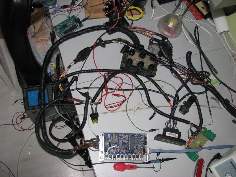
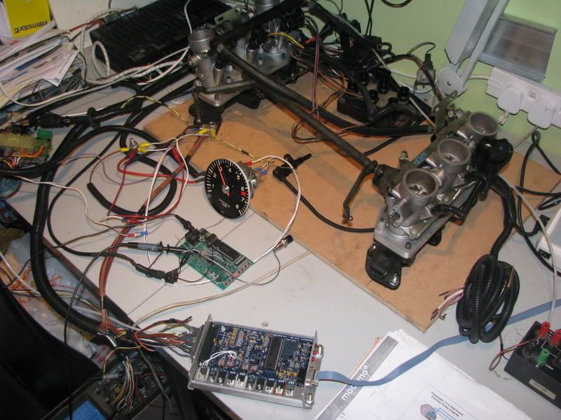
Here is the kit as I've set it up for testing. The Inlet Manifolds and TB are roughly where they would be on the engine.
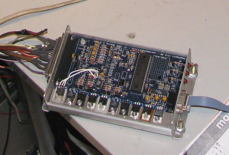
This is the Megasquirt itself, lid removed. I've still to tidy the soldering to the main connector. The white wires inside the box are the Beefed up F-IDLE circuit (Fast Idle)
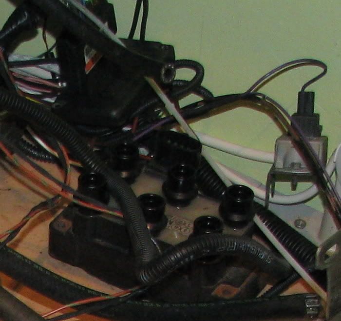
Here is the NS bank of TB's, fuel rail and injectors inboard. The TPS (Throttle position sensor) in the back corner of the engine bay.
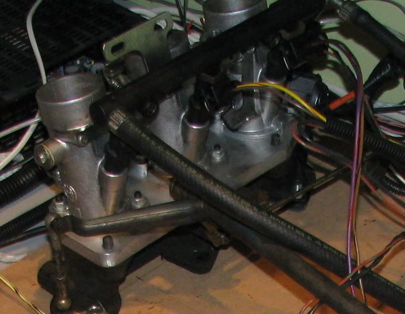
This kit is actually running in the photo, you can't tell but it is.
The circuit infront of the Tacho simulates the VR sensor and 36-1 toothed wheel that would be on the crank. The bottom LED is 500RPM led and the other LEDs show 1K rpm each so showing 3K rpm at the minute. Tweak the POT and the Rev counter follows!
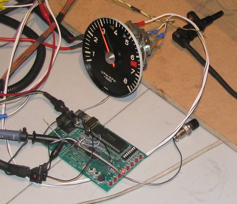
This circuit triggers the EDIS module (Coil pack is un plugged to prevent sparks from flying) which then feeds pulses to the Megasquirt.
and away it goes, Injectors pulsing away. The Tacho trigger comes direct from the MS (I've had to change one resistor in the Tacho to get this to work, and the MS has a small transistor mod done to add additional drive for a tacho but I'm not too sure this was necessary but it does work.
I have The TPS, IAT (Inlet air temperature) and CHT (Cylinder Head Temperature) sensors all feeding back to the PC.
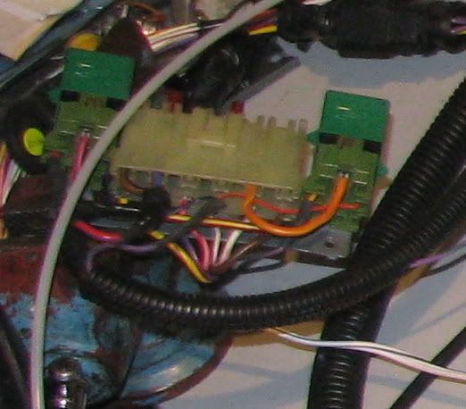
Oh, and here is the Relay block that sits next tot he fuse box up front
All really cool, and almost entirely using Gary71 wiring loom. So Gary, the work you did was all good and your diagrams are spot on, thanks. Just a little tidying required.
I now need to think about how to adapt the throttle linkage, but following the way the Zeniths work is probably a good plan.
Cheers
Tim
Here is the kit as I've set it up for testing. The Inlet Manifolds and TB are roughly where they would be on the engine.
This is the Megasquirt itself, lid removed. I've still to tidy the soldering to the main connector. The white wires inside the box are the Beefed up F-IDLE circuit (Fast Idle)
Here is the NS bank of TB's, fuel rail and injectors inboard. The TPS (Throttle position sensor) in the back corner of the engine bay.
This kit is actually running in the photo, you can't tell but it is.
The circuit infront of the Tacho simulates the VR sensor and 36-1 toothed wheel that would be on the crank. The bottom LED is 500RPM led and the other LEDs show 1K rpm each so showing 3K rpm at the minute. Tweak the POT and the Rev counter follows!
This circuit triggers the EDIS module (Coil pack is un plugged to prevent sparks from flying) which then feeds pulses to the Megasquirt.
and away it goes, Injectors pulsing away. The Tacho trigger comes direct from the MS (I've had to change one resistor in the Tacho to get this to work, and the MS has a small transistor mod done to add additional drive for a tacho but I'm not too sure this was necessary but it does work.
I have The TPS, IAT (Inlet air temperature) and CHT (Cylinder Head Temperature) sensors all feeding back to the PC.
Oh, and here is the Relay block that sits next tot he fuse box up front
All really cool, and almost entirely using Gary71 wiring loom. So Gary, the work you did was all good
I now need to think about how to adapt the throttle linkage, but following the way the Zeniths work is probably a good plan.
Cheers
Tim
Tim Bennett
RHD Targa 2.2T EFI, Triumph ITB's, EDIS and Megasquirt.
"Old enough to know what's right and young enough not to choose it"
#1153
RHD Targa 2.2T EFI, Triumph ITB's, EDIS and Megasquirt.
"Old enough to know what's right and young enough not to choose it"
#1153
-
fourteener
- DDK rules my life!
- Posts: 1318
- Joined: Mon Aug 15, 2005 6:46 pm
- Location: staffs
-
impmad2000
- I need to get out more!
- Posts: 3305
- Joined: Fri Nov 14, 2003 8:31 am
- Location: Leicester, a convenient mid point !
- Contact:
No Gary, clearly not. Everything you did has been spot on, save one badly soldered joint ! It is nice to be able to active bench test before installation thoughGary71 wrote: these damn electrics were beyond me!
Tim
Tim Bennett
RHD Targa 2.2T EFI, Triumph ITB's, EDIS and Megasquirt.
"Old enough to know what's right and young enough not to choose it"
#1153
RHD Targa 2.2T EFI, Triumph ITB's, EDIS and Megasquirt.
"Old enough to know what's right and young enough not to choose it"
#1153

-
impmad2000
- I need to get out more!
- Posts: 3305
- Joined: Fri Nov 14, 2003 8:31 am
- Location: Leicester, a convenient mid point !
- Contact:
-
Matt black70
- DDK forever
- Posts: 510
- Joined: Fri Aug 04, 2006 9:40 pm
- Location: Wolverhampton
-
impmad2000
- I need to get out more!
- Posts: 3305
- Joined: Fri Nov 14, 2003 8:31 am
- Location: Leicester, a convenient mid point !
- Contact:
OK, some movement on this project.
Throttle bodies in place on an engine. And a throttle linkage
Basically, its a cable to each TB, which is how the Triumph TB's are designed to work, linked to the std Zenith primary throttle quadrant , which is how the car is designed. A simple slider to join the two together and some adjusters to match the two spindles.
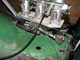
Another view.
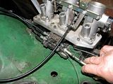
It's scruffy for now. I want to know if it works before making it pretty.
The only problem so far seems to be that the now 6 throttle return springs, 1 on each TB, make the hand operation of the linkage somewhat heavy !!
Tim
Tim Bennett
RHD Targa 2.2T EFI, Triumph ITB's, EDIS and Megasquirt.
"Old enough to know what's right and young enough not to choose it"
#1153
RHD Targa 2.2T EFI, Triumph ITB's, EDIS and Megasquirt.
"Old enough to know what's right and young enough not to choose it"
#1153