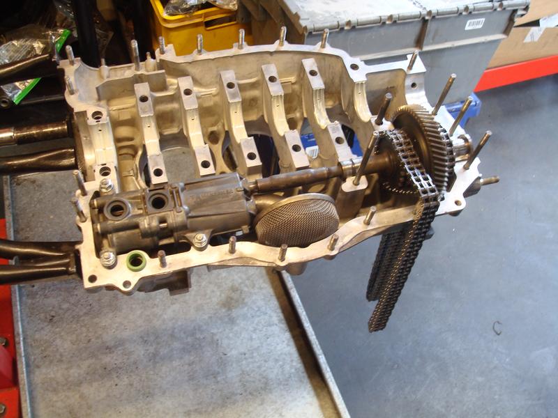
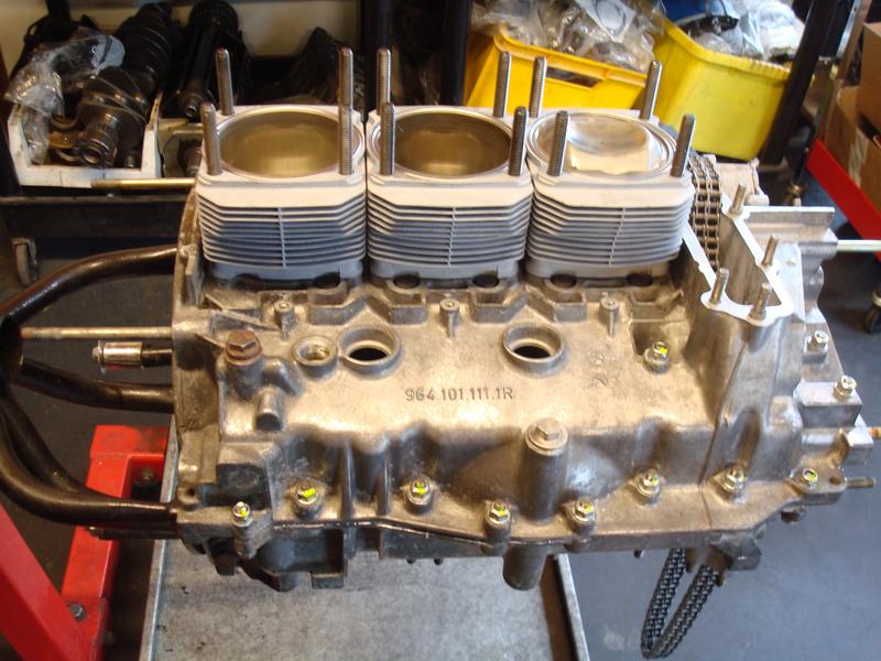
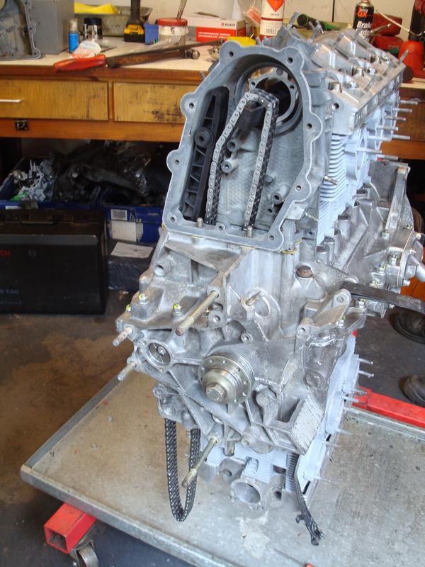
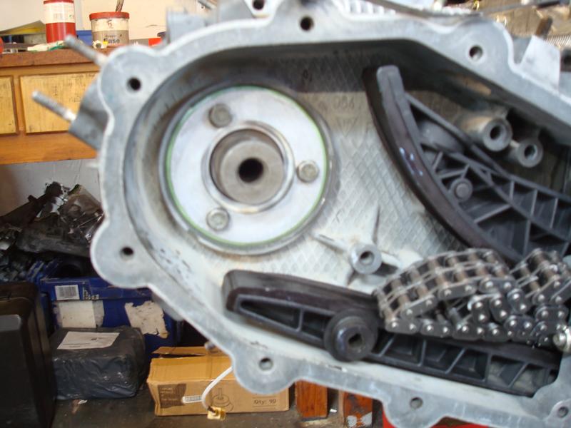
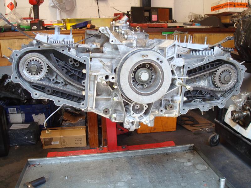
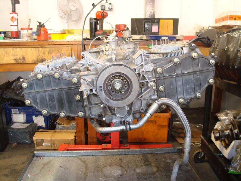
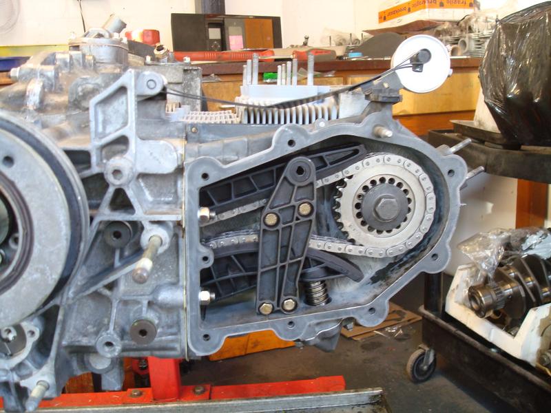
Now the chain guides / retainers / pressure tensioners all fitted up.
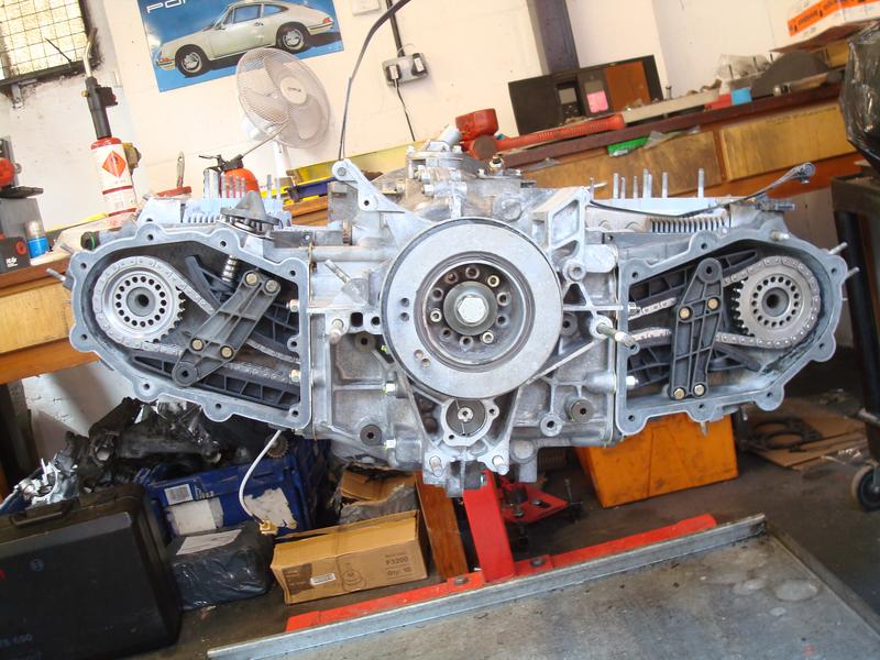
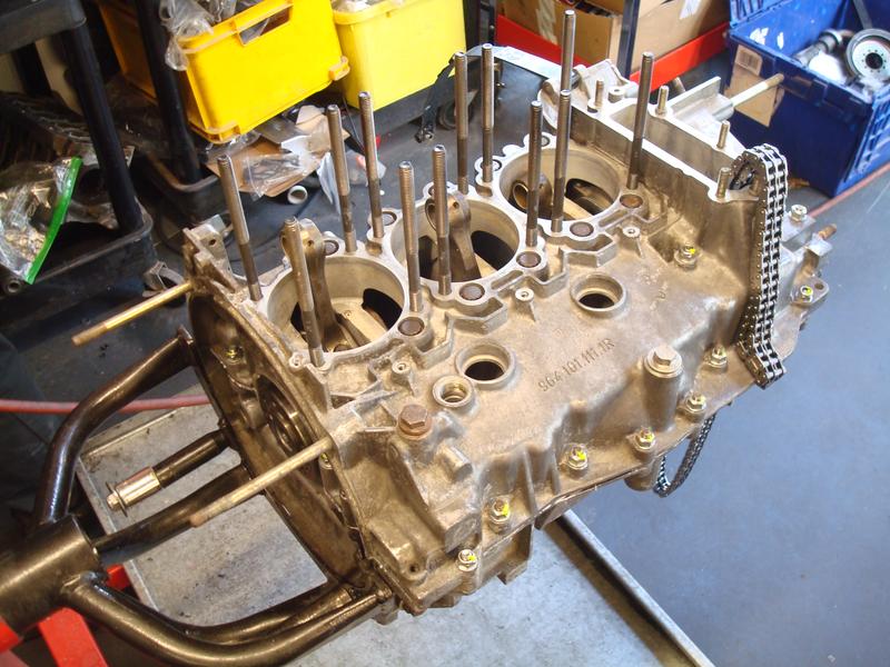
You will see the nuts securing the cam sprocket wheel that we don't know the proper name for has been removed. That is because this is a crucial part of the build. Basically, because the engine is horizontally opposed, there is a factory tolerance for ensure that the chains run squarely to each other. In essence, you place a steel rule across the case on a diagonal below the front pulley. You take a measurement from the rule to the intermediate shaft bearing, and then take off the depth of the rule. This gives you the basis for measuring each side. So on the left side, the rule is angled up toward the toothed cam wheel, and a measurement taken, less the depth of the rule) against the outer surface. You then repeat on the right bank of the engine, and then the difference between the two has to hit a very narrow range. If it is out, you shim the toothed wheel with washers; on each there is a shaped space which only goes on one way, and between 2 and 4 washers per side is the norm. My left bank required 2, the right 4, and this brought them bang on to factory tolerance. Pleasing to note that was how we took it apart, so that part of the job was done correctly on the last build. If this procedure is not followed, the chains will prematurely wear.
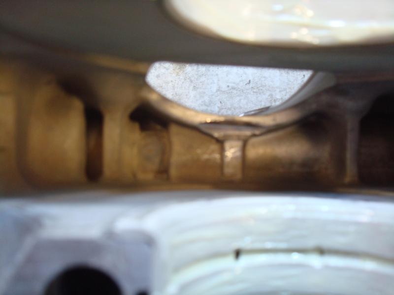
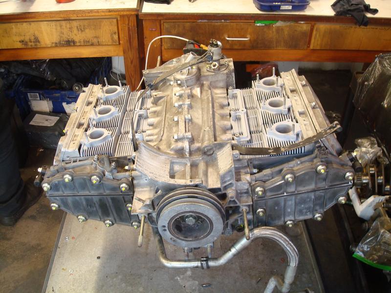
If you look closely, you will see that the toothed wheel thingys fit in a reverse orientation depending on the side of the engine - dish out on the left, dish in on the right. This offset obviously was designed in to allow the factory tolerance to be reached.
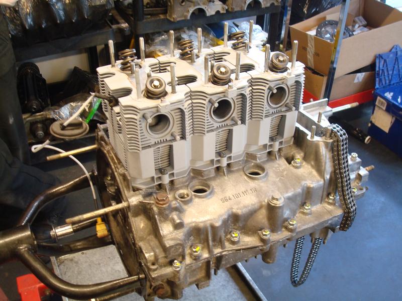
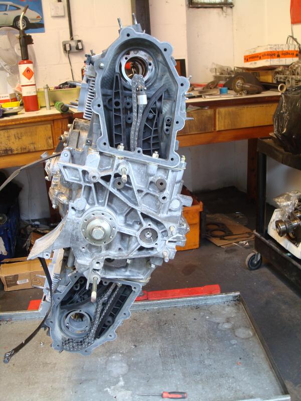
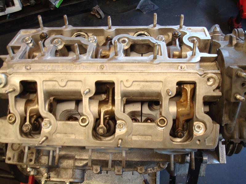
Here is a shot of the most complex part of the whole build, which Gus says sometimes the magic happens on the 2nd go, or you can be messing around for a while. We were messing around for a while.....
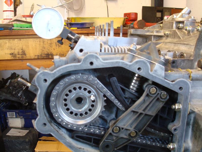
The gauge is secured to the cam carrier and has a needle which sits on the valve - it is effectively measuring lift. So at TDC, you are trying to achieve a precisely determined lift (so number 1 is firing exactly at TDC). Then repeat for number 4, though the order does not matter. I can't quite remember the numbers, but I think our target was 1.7mm lift at TDC (plus or minus 0.1mm)!!
To adjust it you can see a small pin with an M5 bolt in it - you effectively pull this pin in and out and into a different hole to adjust your position until you arrive at the factory tolerance. The problem is that if you are close, pulling the pin out can make the cam jump (or really slip) so your 1.7mm becomes 0.8mm, which then translates as nowhere near TDC when you achieve the 1.7mm you need. Following?
The next issue is that the pin will only fit in one hole perfectly at any time, so you need to create slip between the wheel and the cam to get your target hole to line up. Essentially we had slip when we didn't need it, then grip when we needed slip.....
Luckily, through Angus's experience in sensing by the relative position of where we were on lift vs TDC he manage to estimate where we needed to be, and after a few goes we got it. The second bank, by contrast, was achieved on the 2nd attempt in about 10 mins flat.
So there is cam timing in a nutshell. Frustrating, but super crucial for a good running engine. It can be influenced by wear in the sprockets, and we ended up towards the high end of the tolerance on both banks.
BTW - for those that do / have build engines I won't be offended if you point out any errors / provide correct terminology. This was the first time I have ever seen one be put together, so luckily there was an expert in the room!