1965 Hillman Imp soon with flat six from a Honda

The place to post images of your other cars.

Moderator: Bootsy

yoeddynz
DDK Fanatic
Posts: 54
Joined: Wed Feb 01, 2023 9:02 am

Re: 1965 Hillman Imp soon with flat six from a Honda

Post by yoeddynz »

911hillclimber wrote: Wed Aug 09, 2023 5:47 pm Maga!!
Really interesting to see your solutions, 11/10 from me and many others i think.
I've rebuilt from the crank out 4 911 engines, and that closing stage is a bit taxing.

Looking for more details on the thrust bearing you have added.
I've actually just edited the post to point out that there's another thrust beariing on the flywheel side but I couldn't get a pic of that one because the flywheel adaptor hub is in the way. It'll probably be fine but I have a belt and braces idea I might add between the flywheel and the back plate just in case. Think very slippery plastic.

I'd love to see a thread on how a 911 engine is put together- air cooled and water cooled. Or is water cooling a dirty word around these parts? Should I get my coat?..
911hillclimber
Nurse, I think I need some assistance
Posts: 18924
Joined: Mon Mar 10, 2008 6:26 pm
Location: West Midlands

Re: 1965 Hillman Imp soon with flat six from a Honda

Post by 911hillclimber »

The air cooled engines are very simple but assembly is a bit awkward, but the right ring compressor is key.
Awkward bit with the cases is the Loctite bond has a short cure time, and getting all the bolts in place and torqued up is a bit of a race.
Good news is the cylinders are separate so piston into cylinder is one by one, but locating the wrist pin retention clips is again tricky.

I made a knock-off home made tool to insert the clips, but that was not 100% reliable.

You need patience!
Loads of how to videos on 911 engine assembly on YouTube.

DDK accepts kettle engines too!
73T 911 Coupe, road/hillclimber 3.2L
Lola t 492 / 3.2 hillclimb racer
Boxster 987 Gen II 2.9
yoeddynz
DDK Fanatic
Posts: 54
Joined: Wed Feb 01, 2023 9:02 am

Re: 1965 Hillman Imp soon with flat six from a Honda

Post by yoeddynz »

Kettle engines :-D

I'll have a looksie on youtube tonight!
yoeddynz
DDK Fanatic
Posts: 54
Joined: Wed Feb 01, 2023 9:02 am

Re: 1965 Hillman Imp soon with flat six from a Honda

Post by yoeddynz »

The 'hard' part of assembly completed I can now chip away at the rest of the engine. I'm taking my time, enjoying the process and tinkering with bits as I go along.

The next stage is the oil pump and filter and connecting tubes. First thing to go in was the oil filter pedestal. I looked at the hole for the oil pressure switch/gauge sender and it just didn't look deep enough. I'd tapped it out with the appropriate 1/8" bsp tap and it fitted one switch I had but It just didn't look right for my Imps sender. Only one way to double check. Out to the 'garage' where little imp is safe and dry..

Image

I removed the sender (luckily very easy access on the Datsun engine) and tested it in the hole. Sure enough it only barely started on the thread. Out with the bsp taps and I ran one in a lot further. Much better...

Image

Tested it in place. Easy access.

Image

I wanted to sort this out now as I could make sure the oil ways were completely clear of any swarf etc. Having to tap this hole out in place after fitment would have been a risky thing.

That done I sealed up the filter mounting side with tape and fitted the unit in place..

Image

Oh but not before taking this pic after assembling all the parts together in one place...

Image

I also weighed the block with crank/pistons in place before the oil system went in too. More about weights soon. But back to the oily stuff. I bolted it all in and set up the chains and sprockets.

Image

Some of the tinkering I mentioned as things went together included milling out as much as possible from all the various plates and mounting blocks. No point in extra weight and anyway- the bits looked nicer for it.

Not that anyone will see them.

But I know they are there in all their lighter machined goodness. You can sort of spot some of my Jenny Craig weight loss efforts going on in this pic on the idler gear mount..

Image

That lot in place I moved on to another little job. For oil changes I needed a sump plug. This neat little stainless item arrived from China..

Image

M12 x 1.25 and I didn't think I had a tap to suit. Luckily I remembered about a set of Chinesium taps my neighbour had given me a few years ago. Probably made of cheese but hard enough to tap the required thread I needed. Look at the spelling on the box :) ...

Image

Drain plug sorted...

Image

Cylinder heads will be next on the agenda. Give them a clean, strip them down, check and softly lap in the valves etc etc. I'll also be stripping, cleaning and bleeding the hydraulic lash adjusters. For that job I wanted a tray for all the little bits. I popped over to the neighbours farm as she has many many many chickens. Got some egg trays. She also gave me some sponge cake because she knew Id have run out of the cakes Hannah had made me.

Image

I like cake.

Another job I am mid way through is creating a 'thrust' ring to go between the flywheel and the back plate. It's really just a belt and braces fitment in case because why not. As shown in the last post, I feel that the stock Goldwing crank thrust bearings are fairly minimal. This ring I'm building will only come into effect if the Goldwing item gets worn to much. There's about .0006 ~0007" clearance on the crank. Good oil and not sitting at the lights with the clutch pushed in should help things last. But just in case I will add this. I cut some 8mm alloy plate into a circle and then machined a ring up...

Image

Image

Ordered some special Tecast Pa6c oil impregnated engineering nylon which arrived yesterday. I also got a bit of bar which will be used later on in my gear linkage.

See my lovely shiny ring...

Image

More on this next time.

I mentioned weighing the block earlier. I thought it best to weigh all the engine parts (because curious and couldn't wait actually). The block with crank/pistons was 36kg on the pretty accurate bathroom scales. Everything else I weighed with the digital scales. I wrote stuff down and took a pic..

Image

Pretty happy with that really. It includes the clutch assembly and the engine side of the engine mounts. When I first started stripping this engine down many moons ago I had always hoped I might see a final weight of around 80kg - but unrealistic when the block and heads are 56kg alone. I'll wiegh the Datsun engine when its out but google sources claim my A12 is 87 kg so I'm stoked with a circa 10kg increase there. The Subaru leone transmission is about 9kg heavier than the Imp item.

The big benefit is that the flat six is shorter in length and majority of its weight is down low in line with the crank - not up high like my current Datsun is. I'm super happy with how the current car handles so this will be a decent improvement on that.

Plus I get the rear parcel shelf back for shopping bags! :)

Since I had an empty workshop for a bit I thought I'd reunite Impy one with impy two for a few nights. Maybe I'll get baby imps?

Image
911hillclimber
Nurse, I think I need some assistance
Posts: 18924
Joined: Mon Mar 10, 2008 6:26 pm
Location: West Midlands

Re: 1965 Hillman Imp soon with flat six from a Honda

Post by 911hillclimber »

Several things here:
CAKE in the garage, you are truly blessed.
Those custom parts are fab, love the engineering.

Surprised at the Honda's weight, thought it would be less, but the Subaru box is very light. I have a 1996 Sti gearbox here from my previous hillclimb car, and that certainly is not light.

All looking really good! :)
73T 911 Coupe, road/hillclimber 3.2L
Lola t 492 / 3.2 hillclimb racer
Boxster 987 Gen II 2.9
yoeddynz
DDK Fanatic
Posts: 54
Joined: Wed Feb 01, 2023 9:02 am

Re: 1965 Hillman Imp soon with flat six from a Honda

Post by yoeddynz »

Cake was good. I like cake.

I was unrealistically thinking the engine might come in at circa 80kgs but really that was a bit optimistic considering the block and heads are 56 alone. Its still very light for a 6 cylinder inc the full clutch and some engine mounts. Not too much more than the datto engine either :)
yoeddynz
DDK Fanatic
Posts: 54
Joined: Wed Feb 01, 2023 9:02 am

Re: 1965 Hillman Imp soon with flat six from a Honda

Post by yoeddynz »

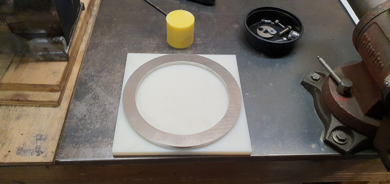
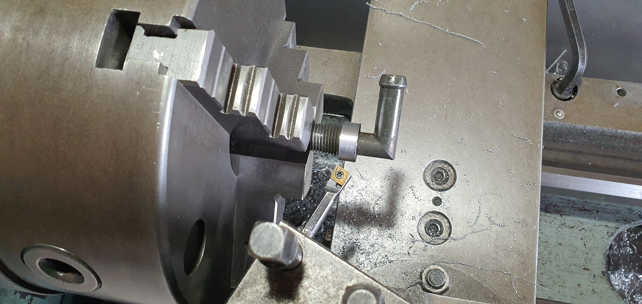
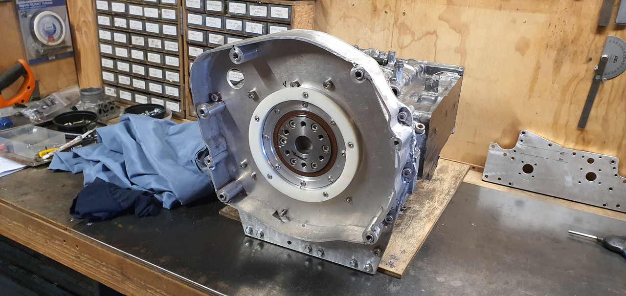
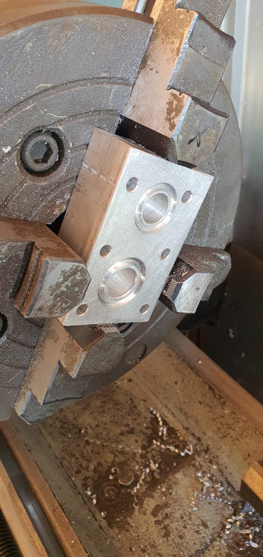
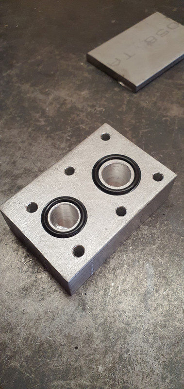
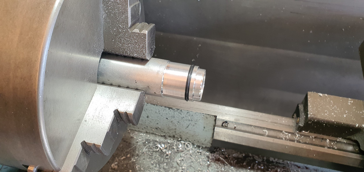
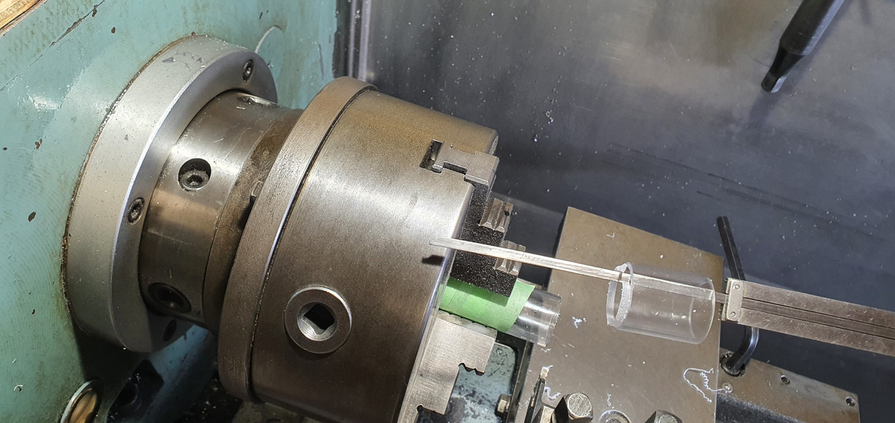
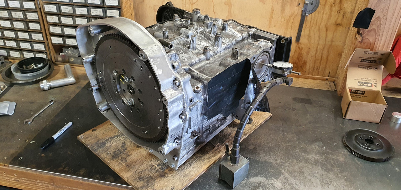
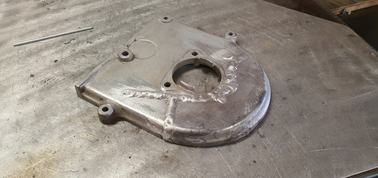
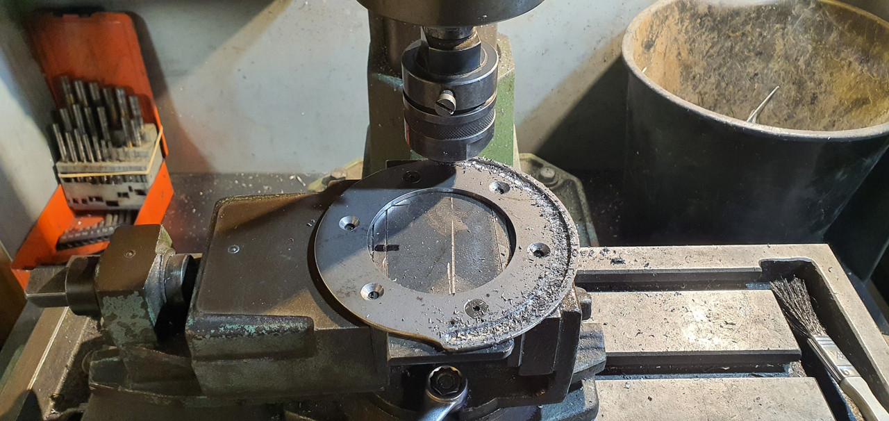
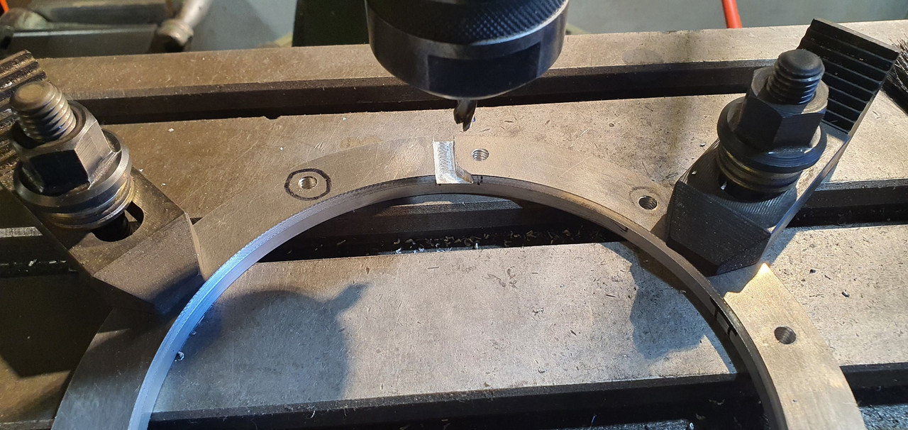
So last time I popped by I was talking about my ring piece. I machined it to suit the location around the rear main seal holder, then cut out another ring piece from the engineering plastic. Harder to cut with the jigsaw than I expected. Put it in the lathe, machined it to the same size as the alloy ring. Machines really nicely. Makes lots of fine mess, much like a very not so tasty candy floss.I then drilled and tapped the alloy ring concentric to the main seal holder on the bell housing backplate. Then drilled the plastic ring, spot facing the holes and bolted it to the alloy ring. I now had an easily replaceable large thrust bearing.


Image


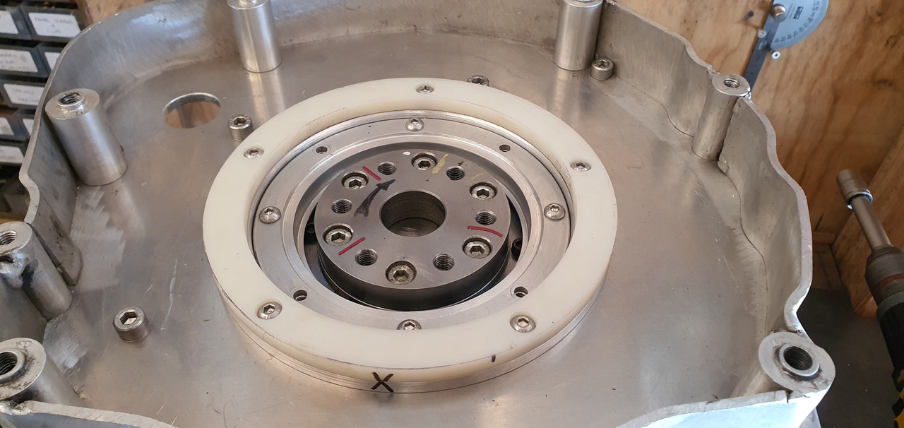
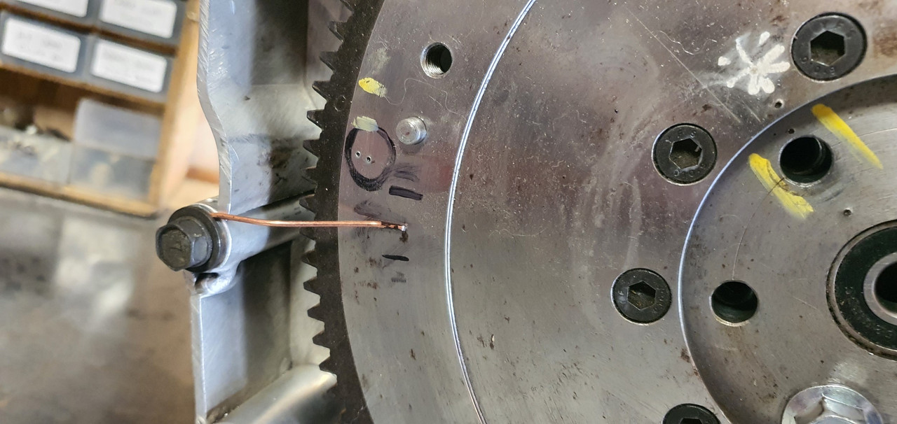
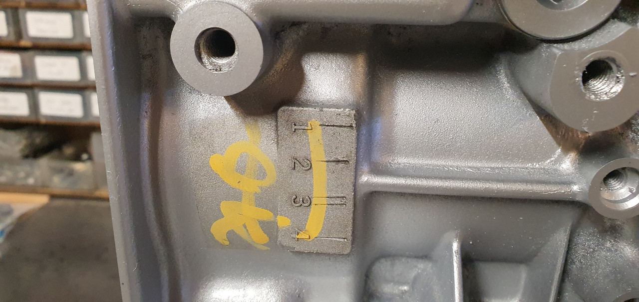
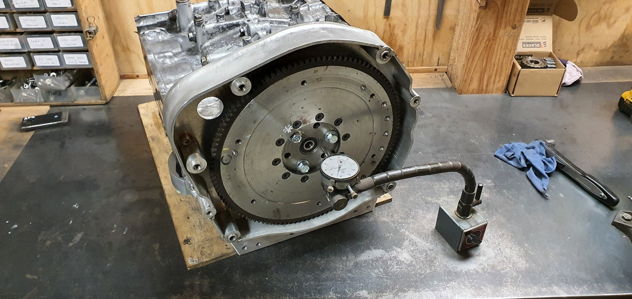
Next was the tricky bit. The crank has about .007" lineal movement on the crank. I wanted to set the thickness of the ring just so there's a smidge less because it will bed in. First I had to get close enough I could start accurately measuring it but I couldn't get in between the back plate and the flywheel to measure in any accurate way. So I used some plastigauge between the flywheel and its hub. Id fit it in place carefully and because the plastic was slightly too thick the plastigauge would show me how much I needed to remove from the thrust face before there was no lineal movement at all when the flywheel bolts were cinched up.


Image


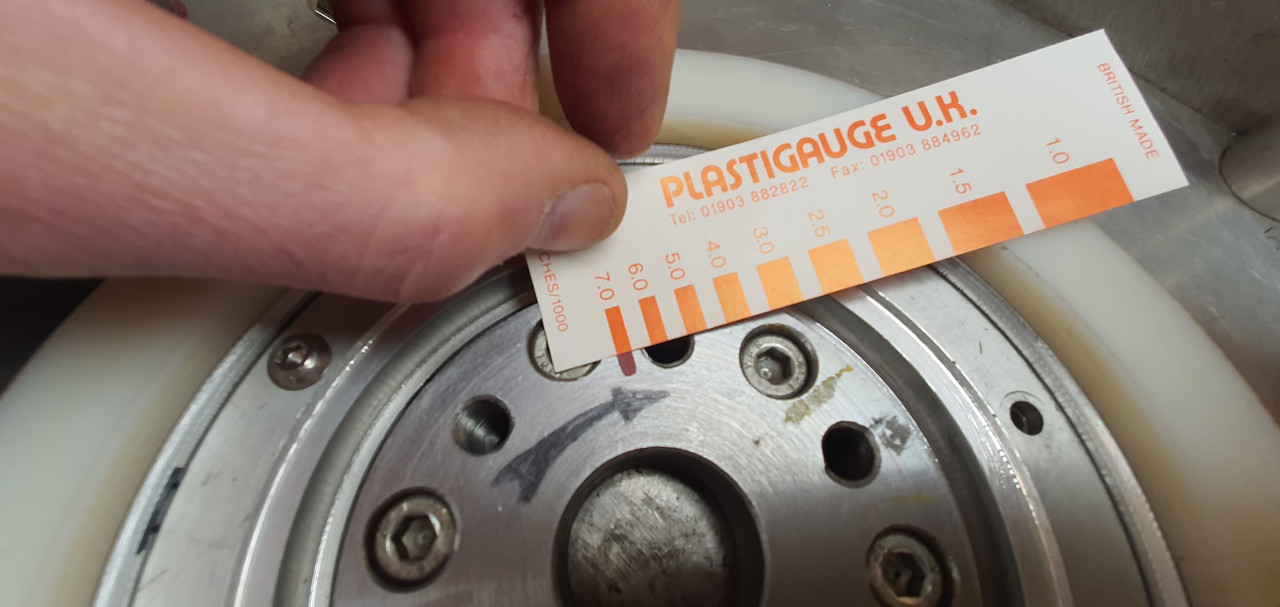
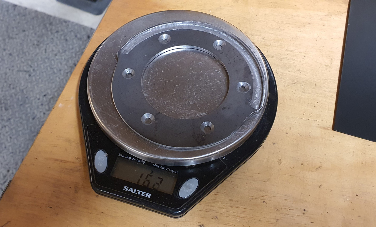
Once I was at that point I could take a skim off the plastic and I ended up with about 5-6 thou movement. Perfect.


Image


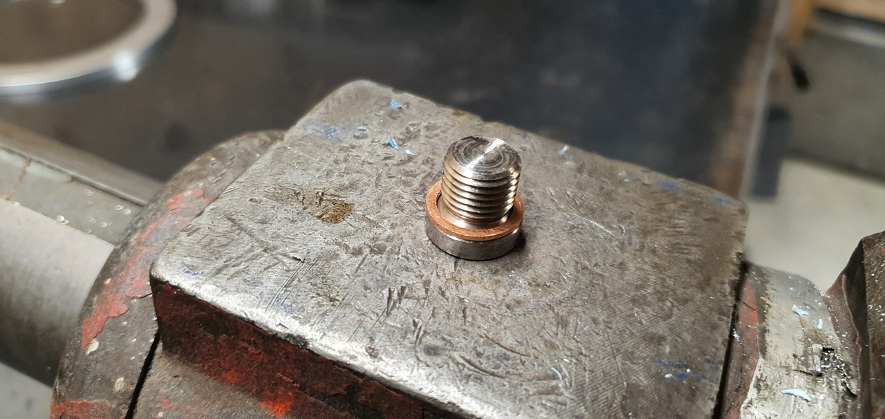
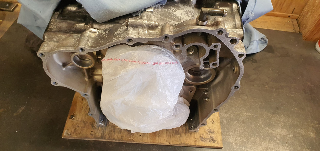
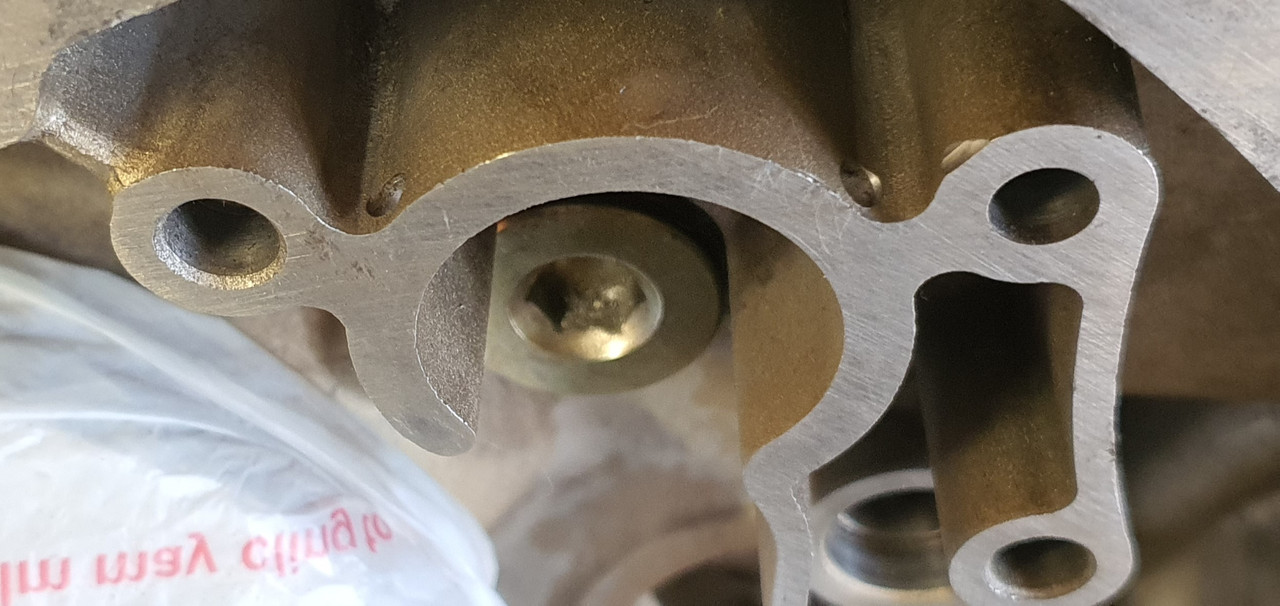
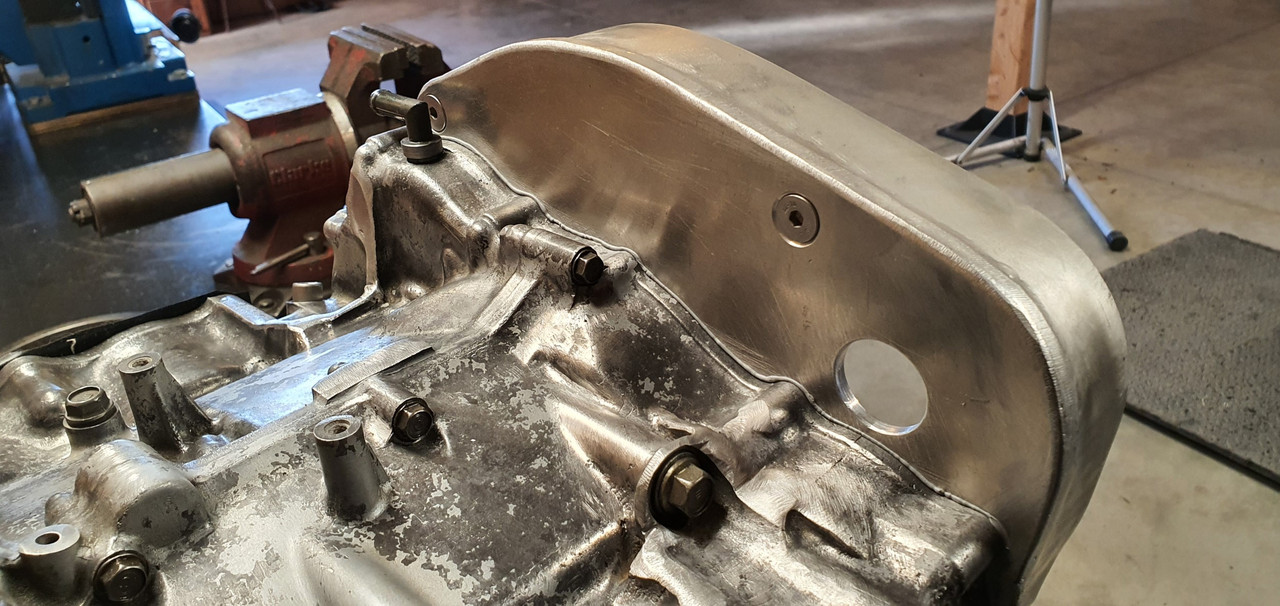
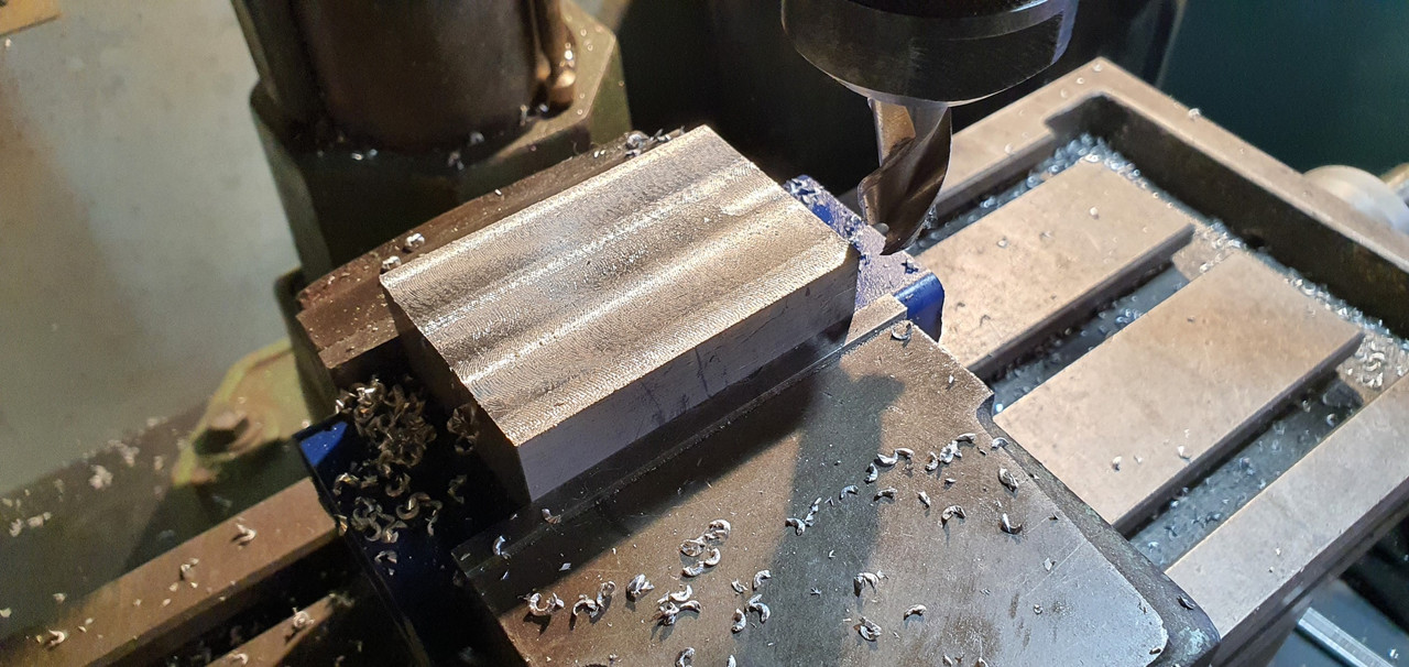
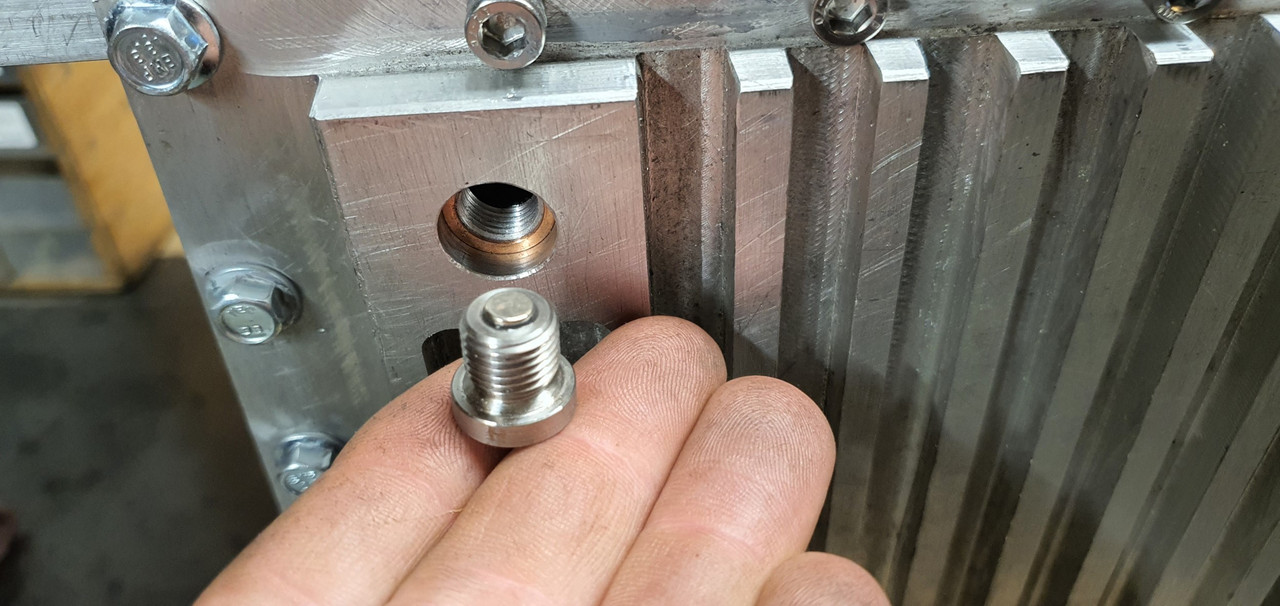
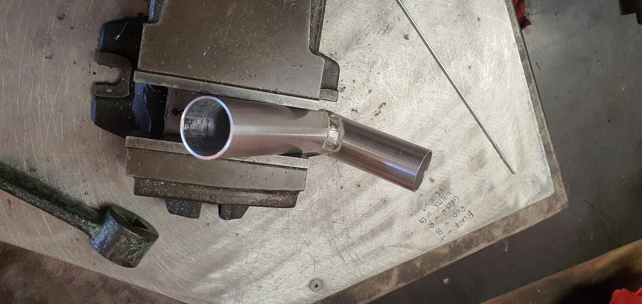
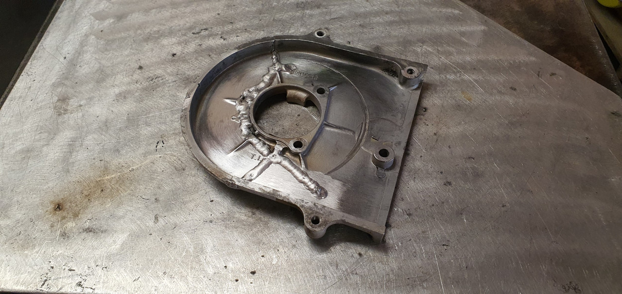
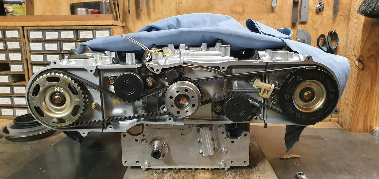
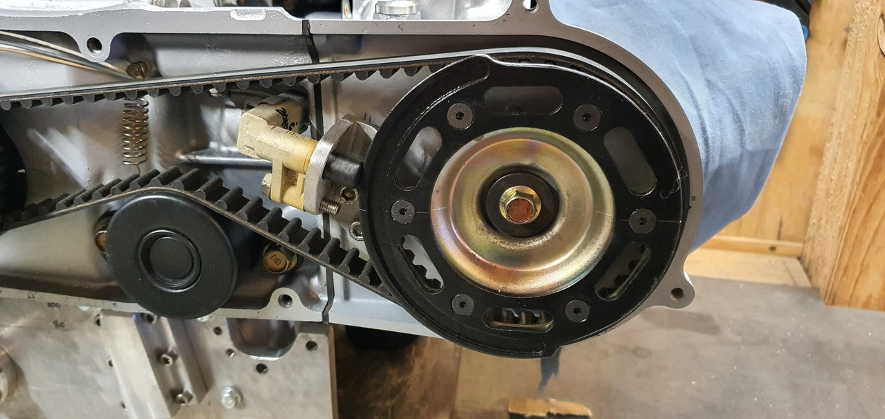
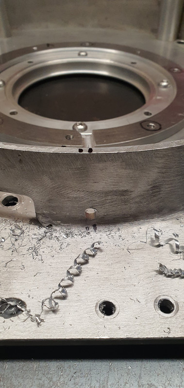
Because its an English car, irrespective of what engine is fitted it'll no doubt leak. So in order to help it drip oil properly I added a tiny drain hole below the rear main seal..


Image
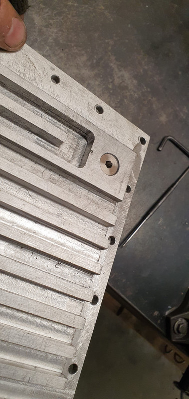
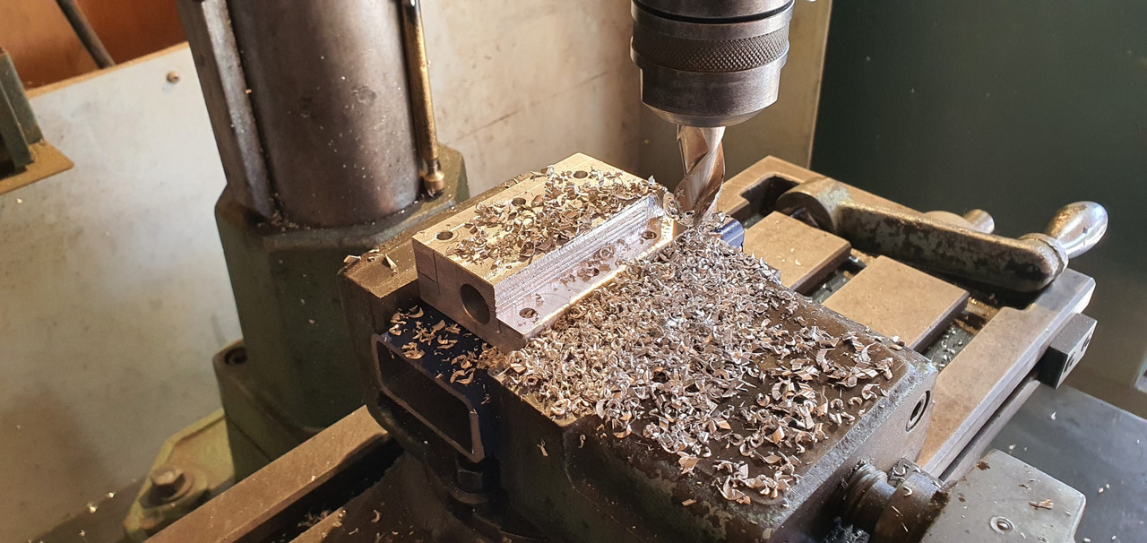
...and a hole in the bottom of the bellhousing. Always horrible having a build up of oil in a bellhousing, flicking all over the clutch etc. Now it can leak gracefully onto a driptray :)


Image


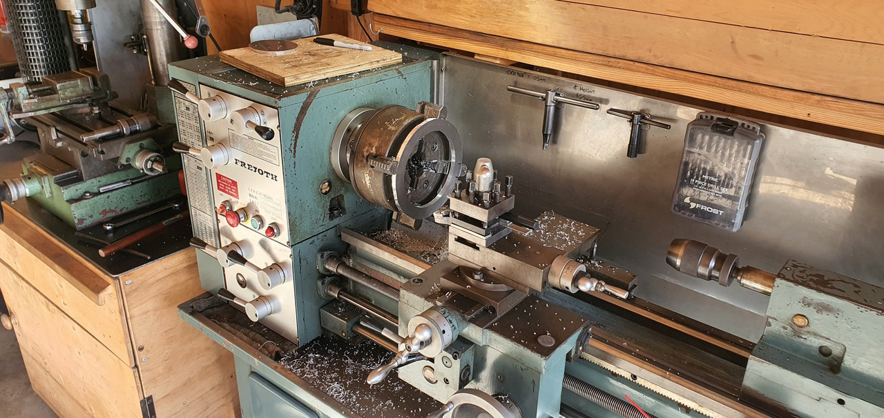
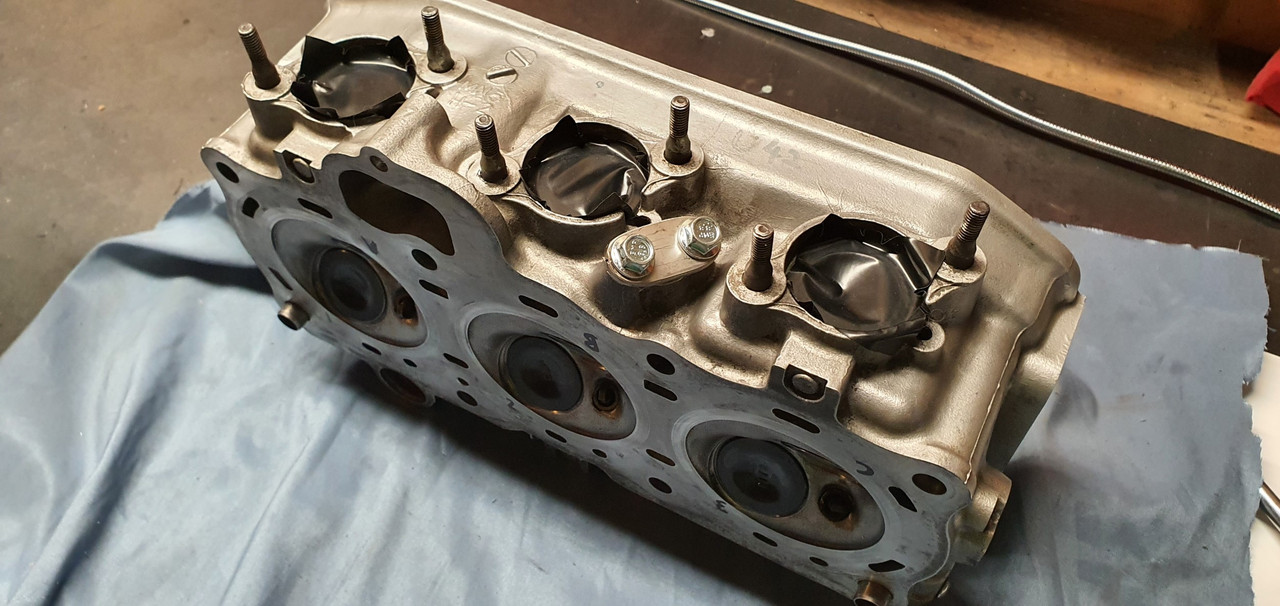
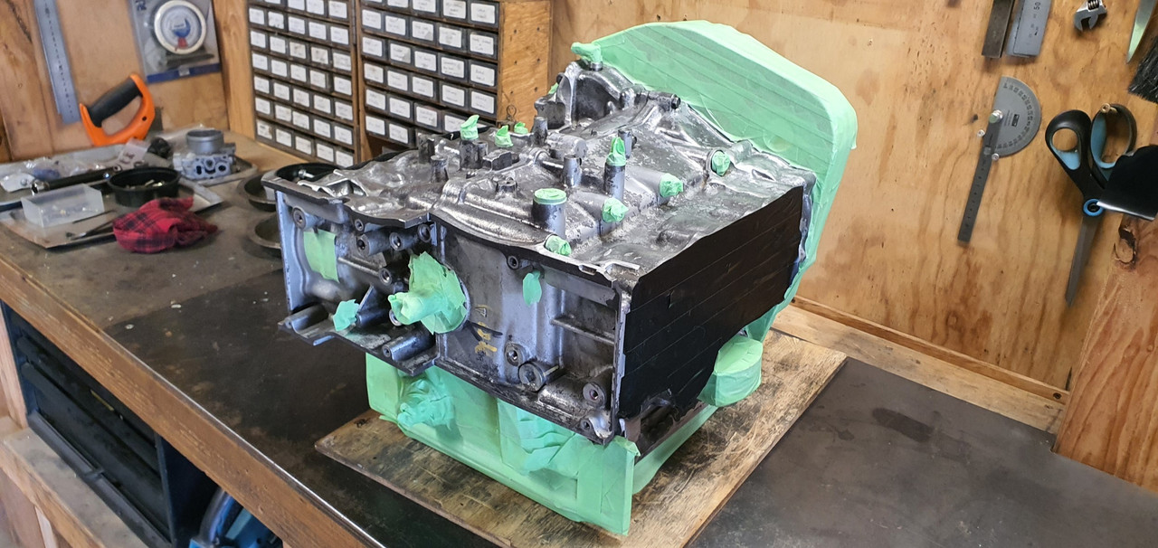
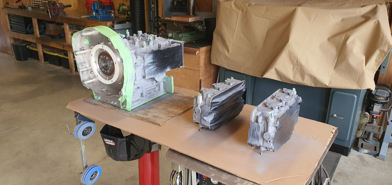
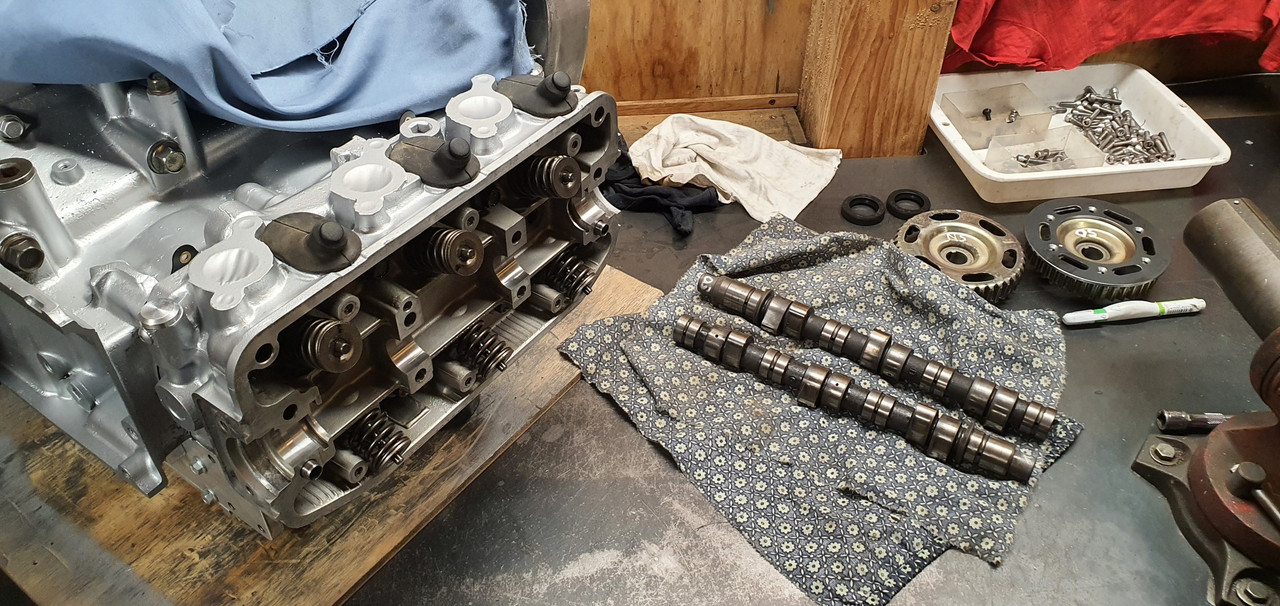
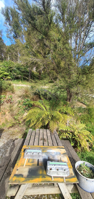
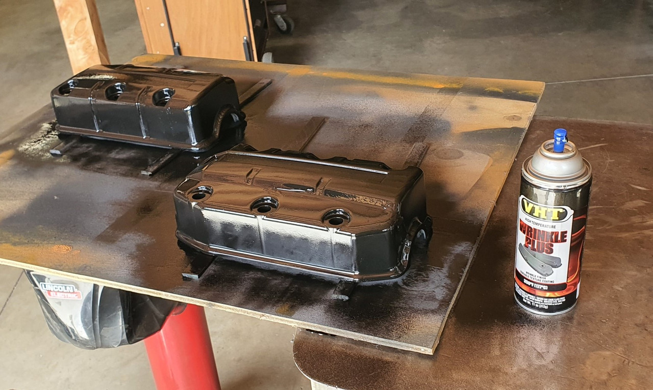
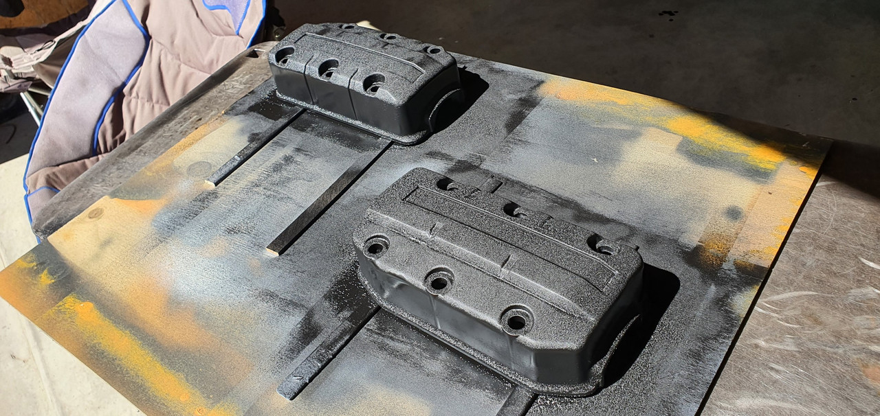
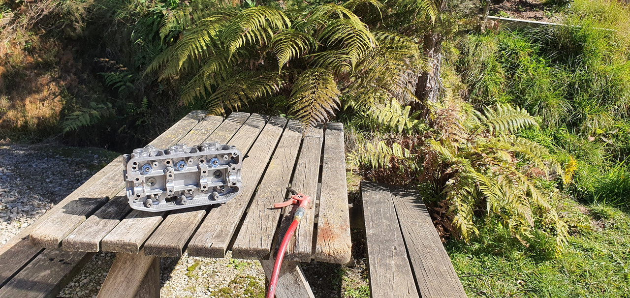
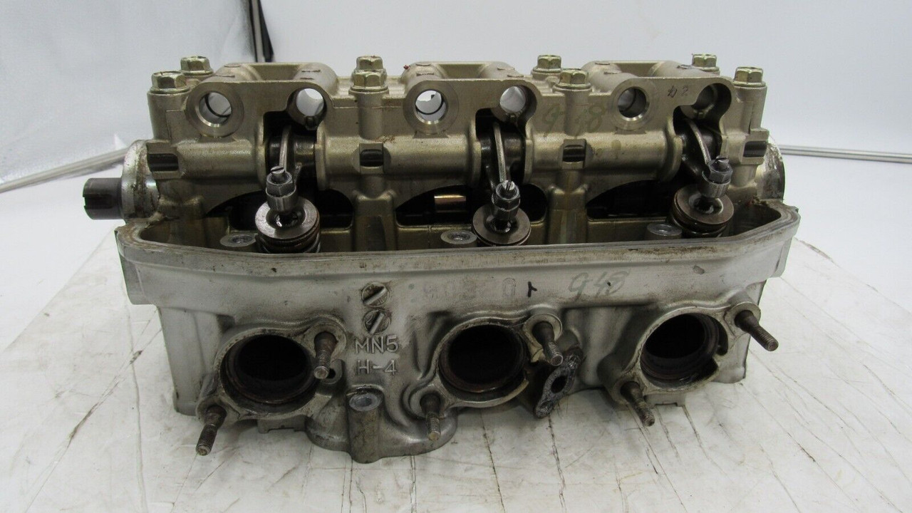
I put the dust sheet over the block and pulled the cylinder heads out from under the bench. Gave them both a clean as best I could with the valves in place. A nice job to relax into in the afternoon sun...


Image


Image


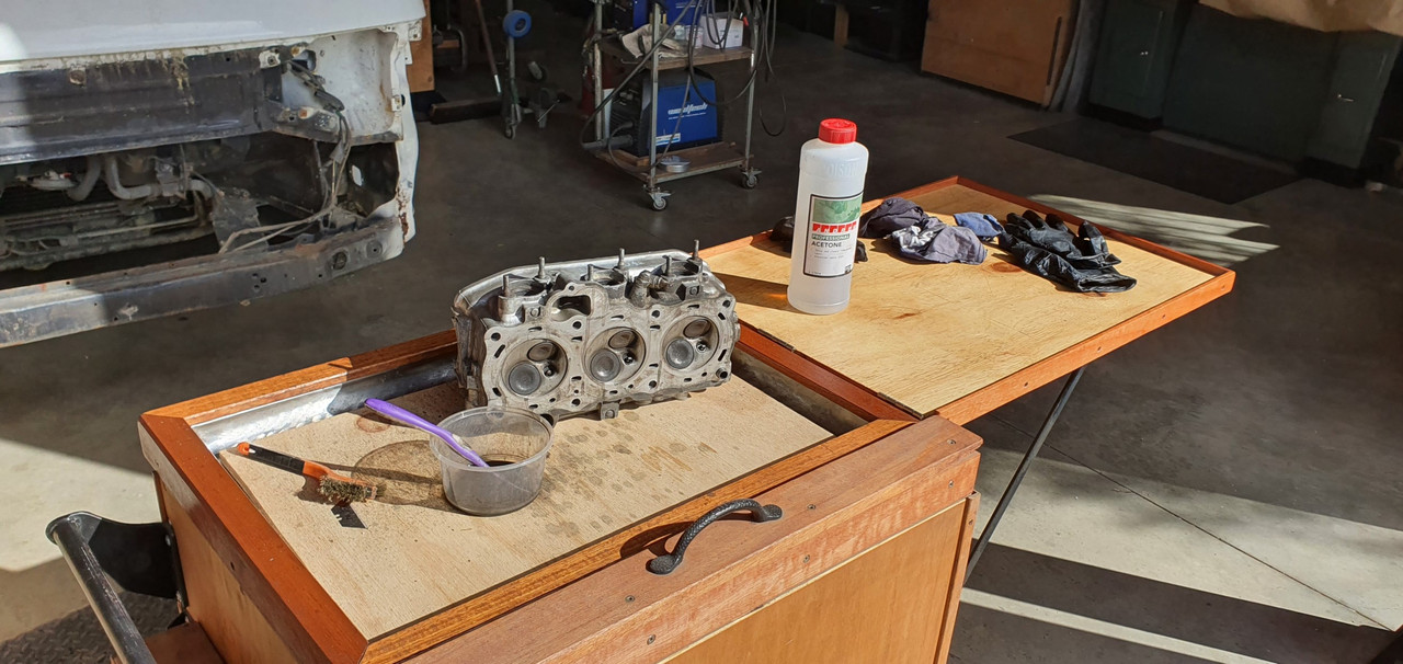
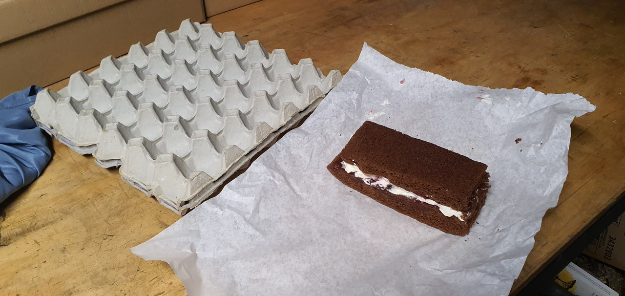
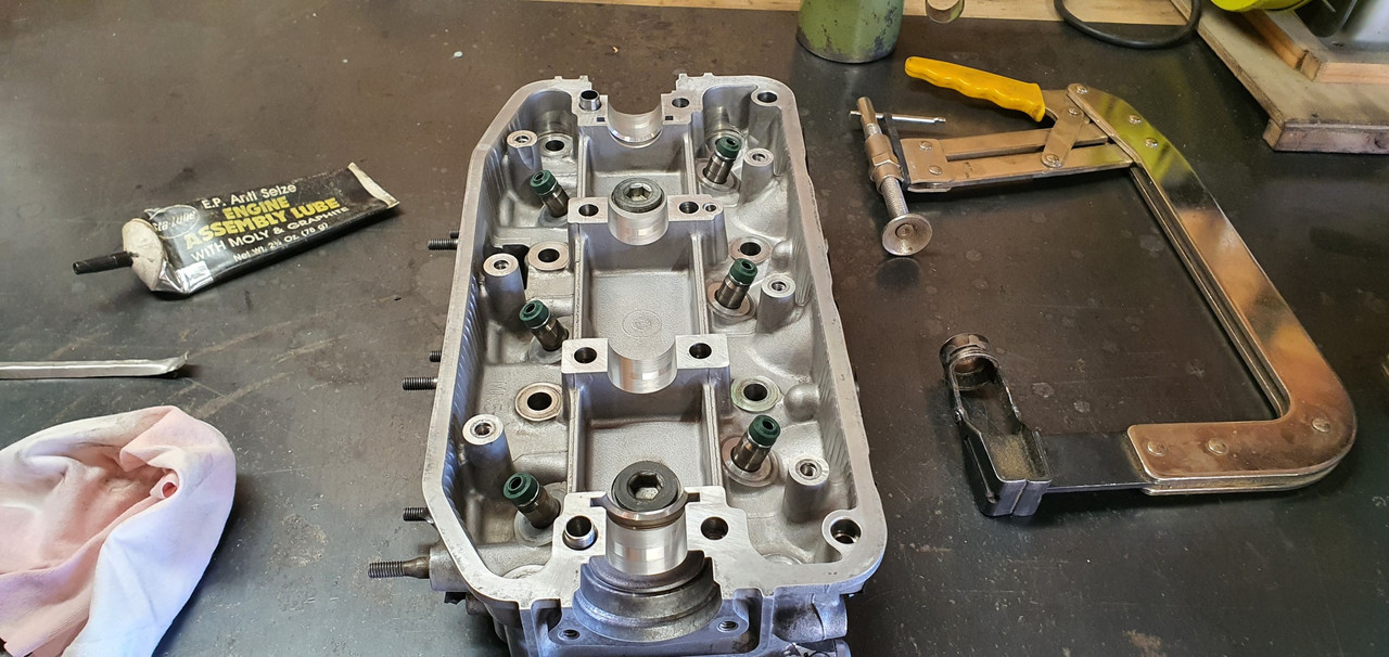
Heads much cleaner I put one aside and set up shop on the bench to remove the valves and clean them up. I was going to put the bits in an egg tray but it wasn't really ideal so instead a plastic tray with moveable partitions. Very careful not to mix any bits..


Image


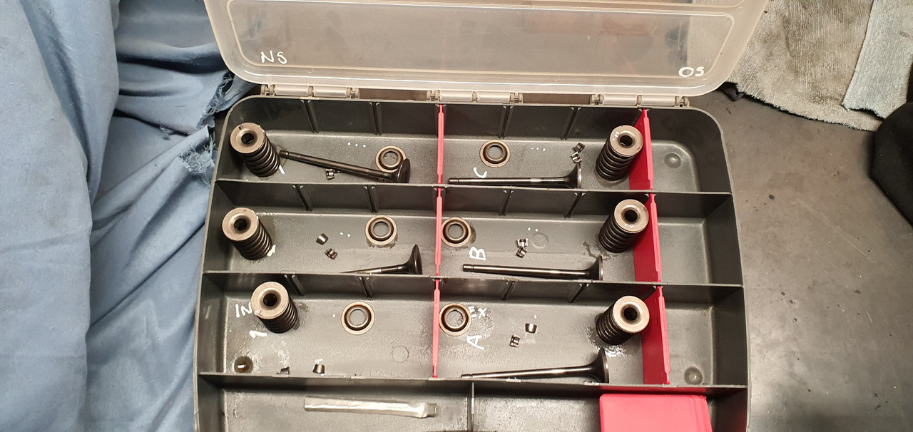
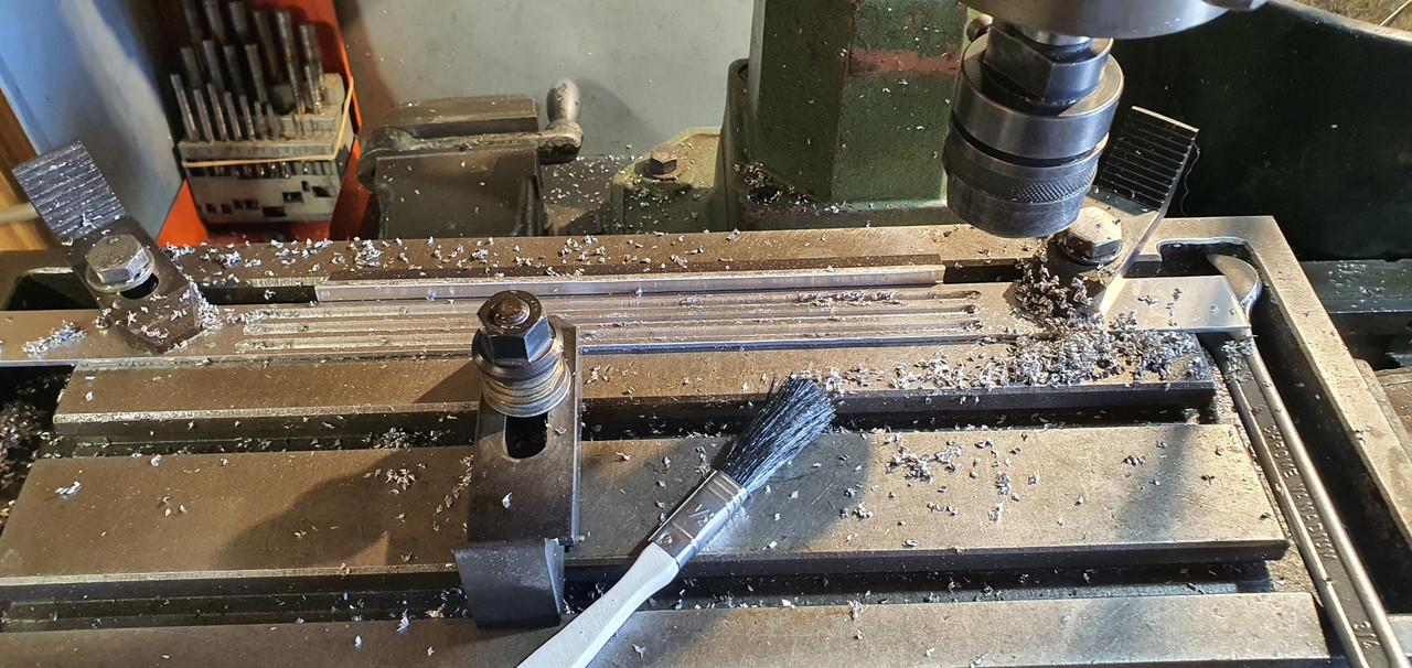
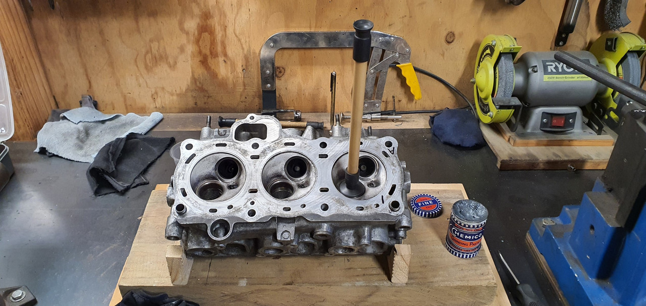
The seats and valves were all really good. A bit of carbon build up behind the heads on the exhaust valves but they all cleaned up mint in the lathe with a wire brush. The stems had barely any sign of wear and were jiggle free in the guides. More signs that this engine really is a low mileage, well maintained unit.I made a basic wooden jig to hold the heads at the valve angle so making for an easy time to accurately lap the valve seats clean. They came up sweet with minimal lapping.


Image


Image


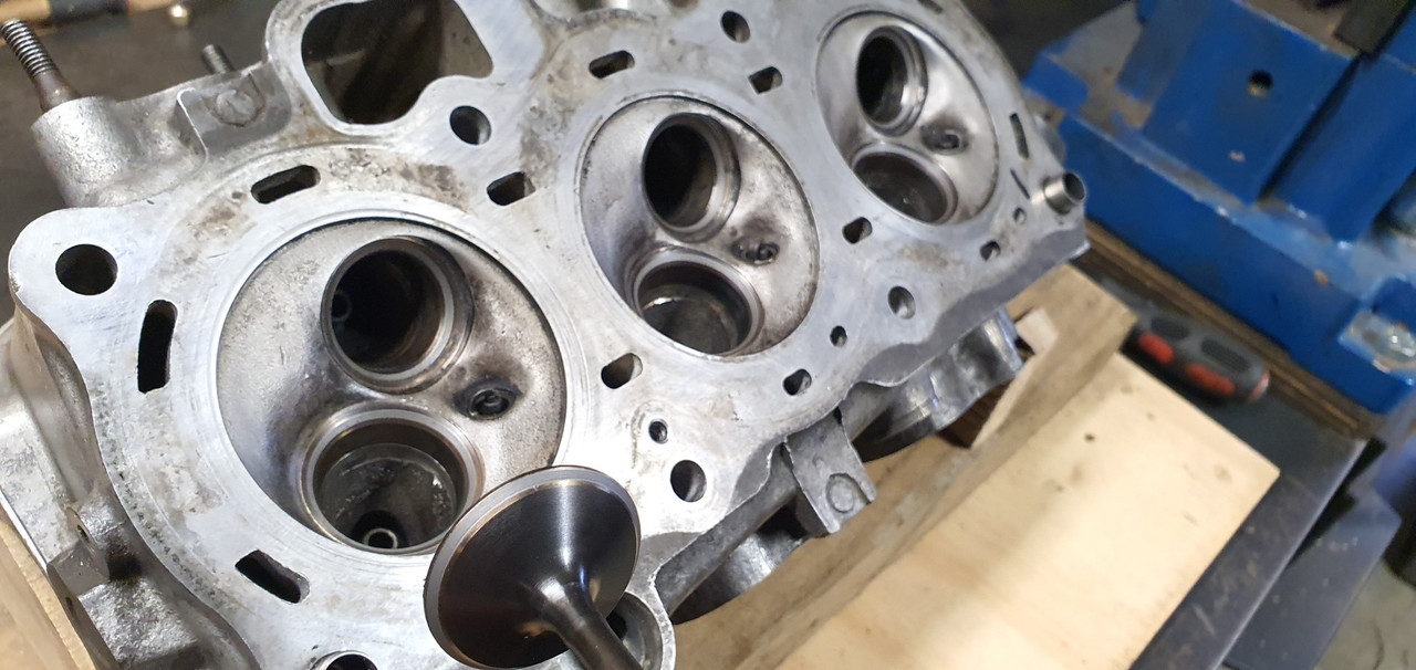
Happy that the valves and seats were good I decided to give the ports a little clean up. Nothing too flash but there's a few casting ridges etc that I could remove...


Image


I was going to use the air grinder but the Dremel seemed a lot more suitable, especially when I remembered I had the flexible extension I've never used before. Wow!! Its perfect for the job.
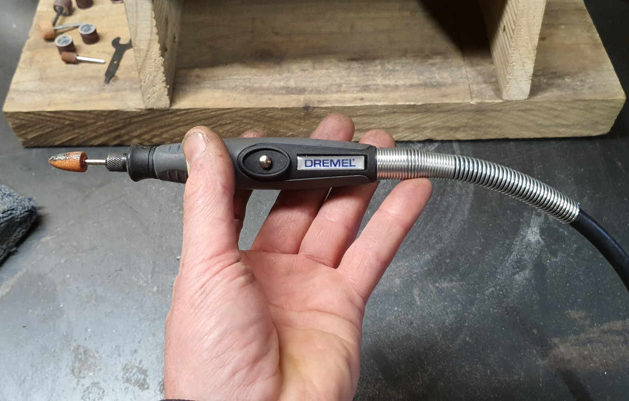
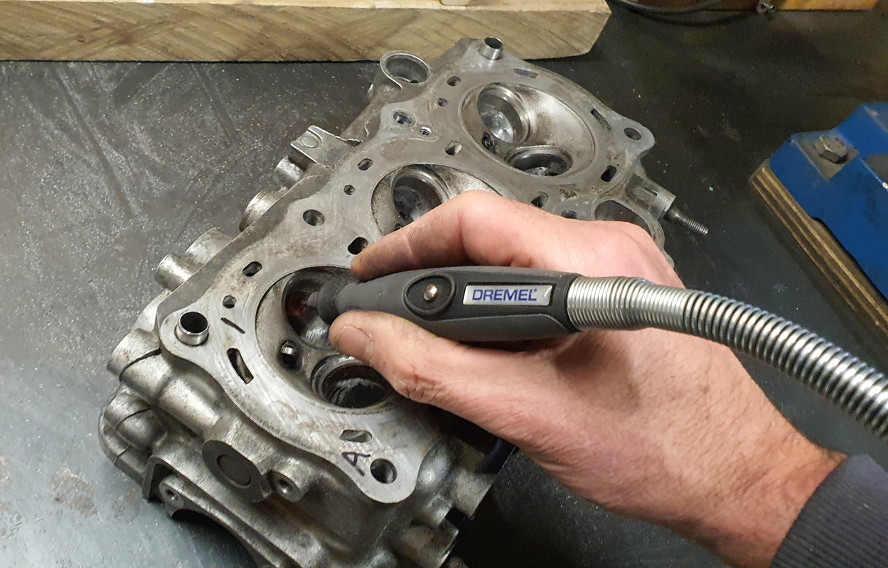

Image


Image


Image


Just a tickle..


Image


Image


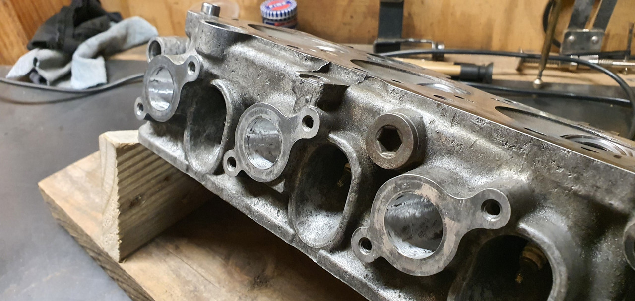
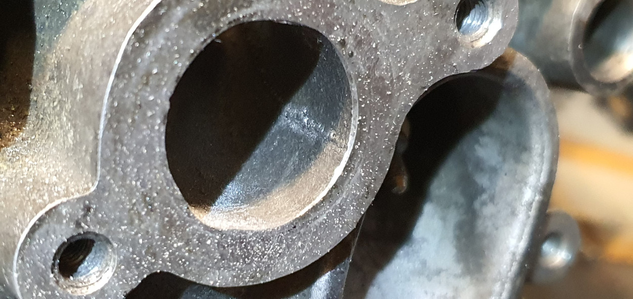
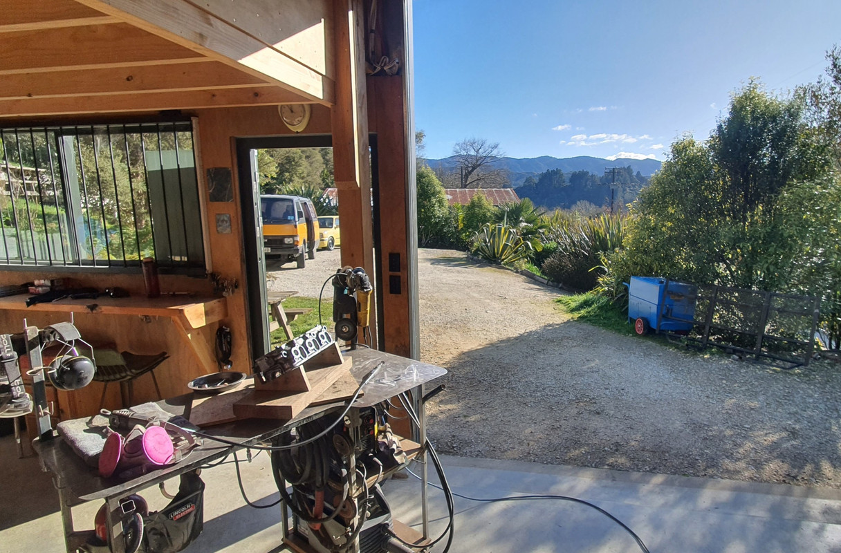
Into the sunshine and swapped over to some tiny sanding drums to smooth things up.


Image


I wanted a nice clean but 'rough' finish on the inlet ports. Certainly not polished. The exhaust ports were smoothed off a lot more but not polished either, a waste of time for very minimal gains on one of these mildly tuned engines I think. If this engine swap works out well, without grenading the transmission etc then another set of heads will be a fun thing to play with. More on this subject later.


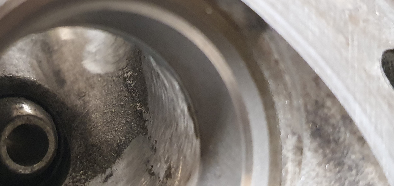
Once the port clean up was completed I fastidiously cleaned the heads and blew away any signs of anything that might cause harm if it were to get into a bearing surface. Brake cleaner and the airline was perfect for this.


Image


Next I sealed up the ports and fitted the plugs back in place..Image


Brand new stem seals, the ones I'd ordered from Norway of all places and they had taken bloody ages to get here, but here they are..


Image


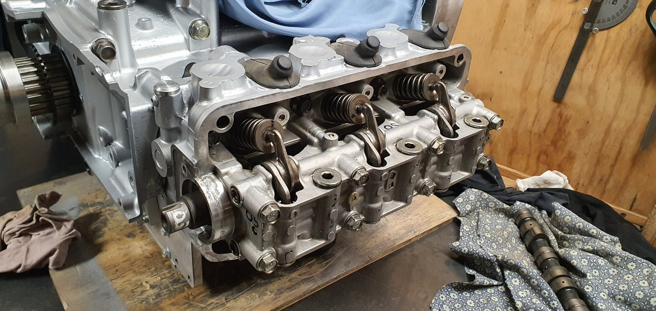
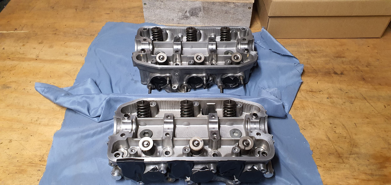
Refitted the valves and called it done. Rise and repeat for the other head. Then I had two nice clean heads ready for service..


Image


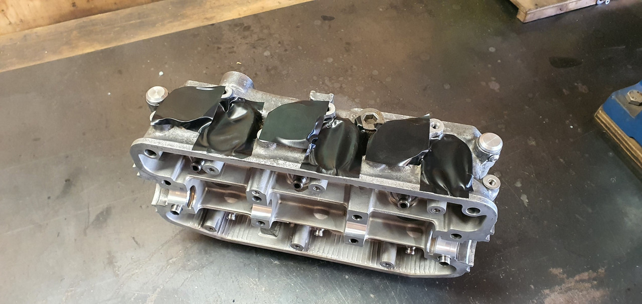
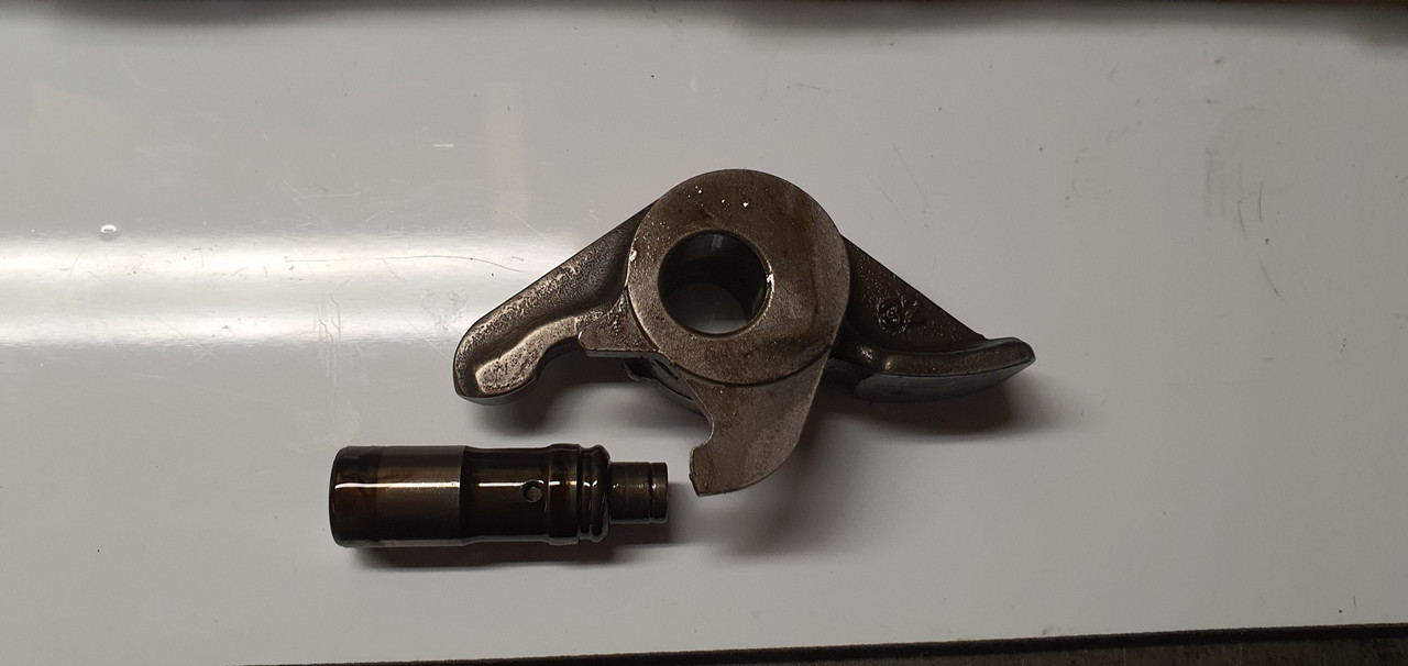
Next job was the cam follower assemblies. Again, like the heads, not too dirty, no real signs of oil staining etc but certainly in need of a clean anyway.


Image


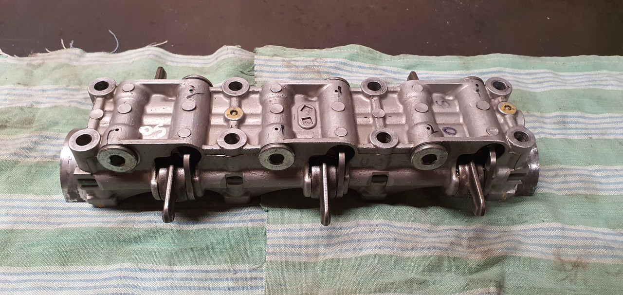
The underside showing the rockers..


Image


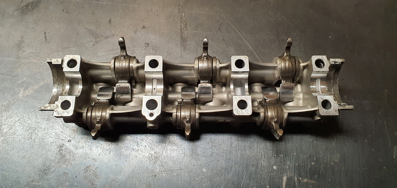
Plastic tray compartments cleaned and shuffled about to suit their new role. One assembly at a time.


Image


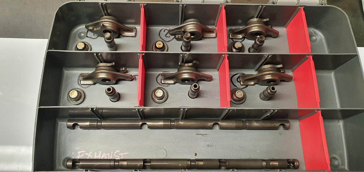
The rockers, followers and rocker shafts show next to no wear. The lack of needle roller bearings between the rocker and the eccentric lash adjuster cam thing dates this engine to something around early 90s. If I'm correct I think they added needle bearings around 1993.


Image


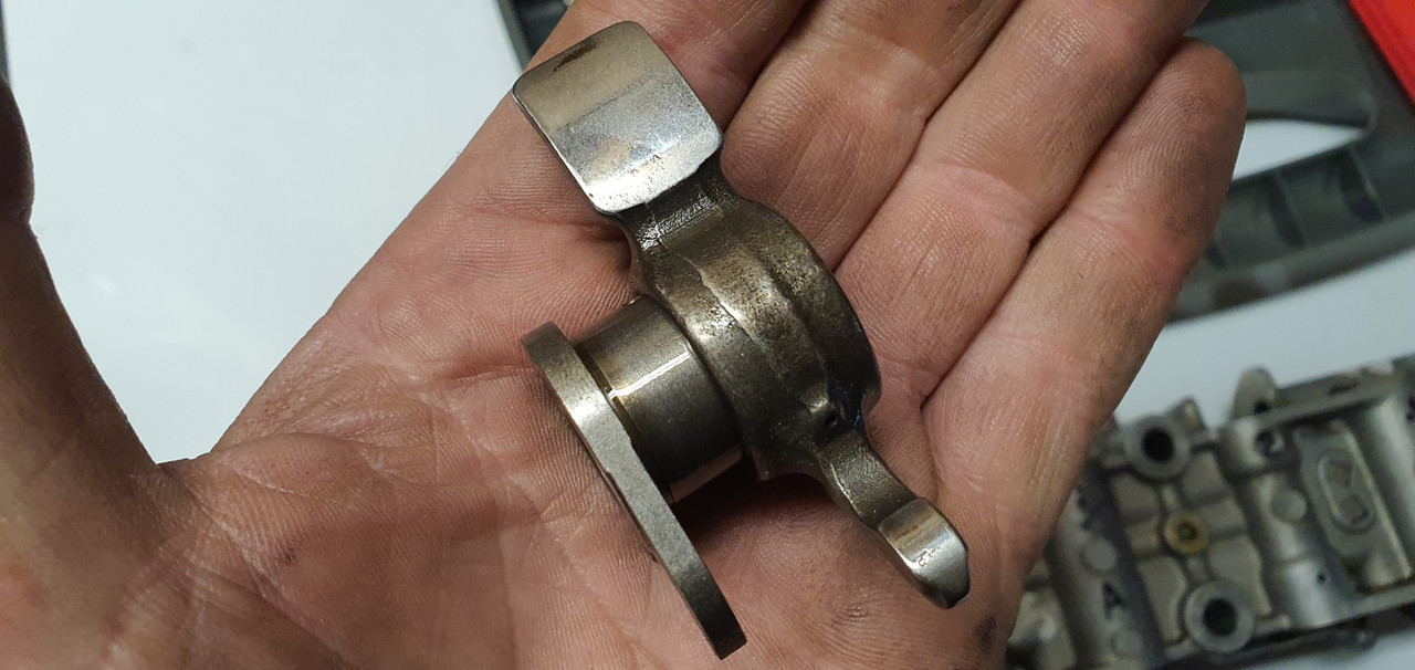
Here's a pic to show how the hydraulic lash adjuster moves the cam and so take up the slack in the rocker..


Image


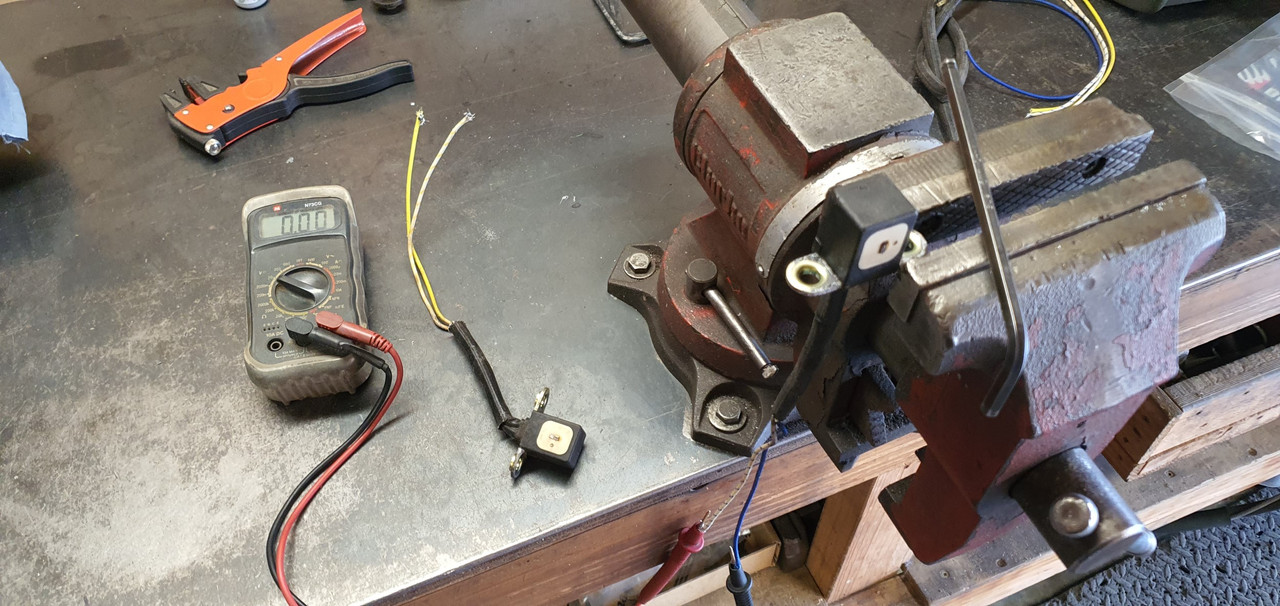
These adjusters are like many you might find in car engines. To make things easier to explain here is an exceptionally accurate, highly detail and finely drawn technical drawing I just did on my phone...


Image


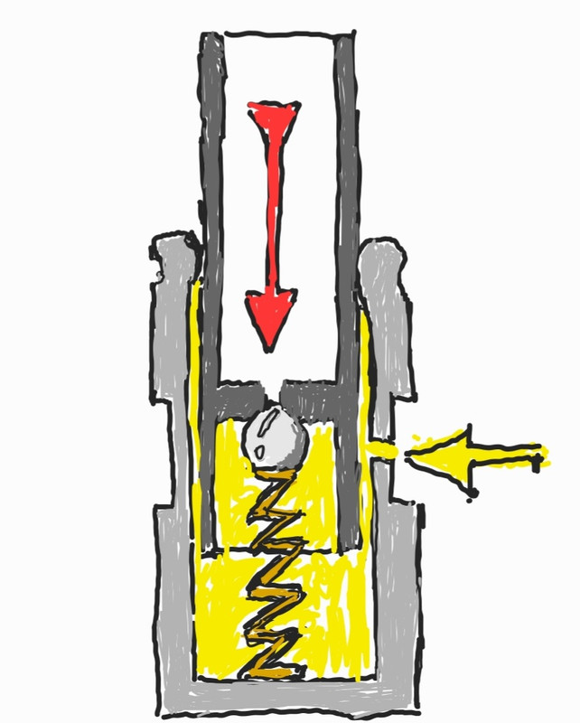
Oil is contained with the the unit and held under pressure by the engines oil system, fed to each adjuster by oil ways within the cam follower cradle. The piston part, uppermost, is a very fine fit into the base and held in place by crimping. In order for them to work properly the air must be removed from the adjusters and that's what the spring loaded steel ball is for. Push that in (red arrow) and air is expelled. If they were to be left on their side or upside down the oil within will eventually drain out and air introduced.

From what I can work out they don't self bled and the oil within is not constantly renewed. So over time the oil will break down and become dirty just from the minute amount of metal on metal wear within.

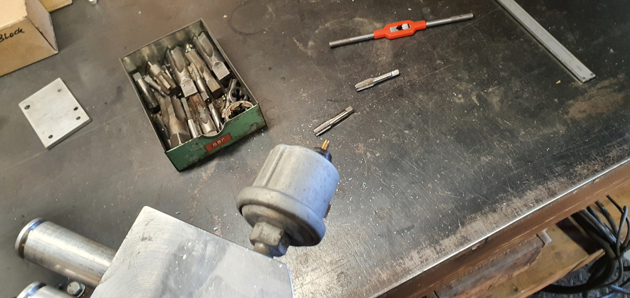
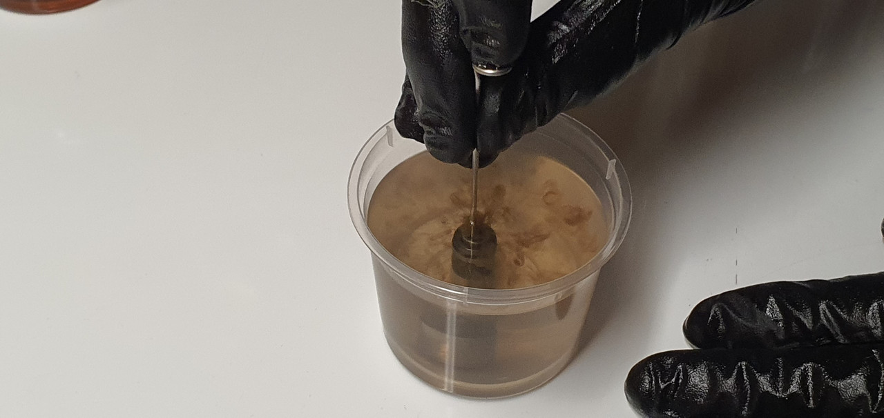
Mine certainly showed as much as I cleaned them out and they took a good bit of working before they stopped showing any wisps of dirty oil. There is a special Honda tool that is used to push the ball valve in. I machined one up in aluminium with a bit of tig rod set in the middle but in use it wasn't as good as just using a neatly shaped bit of 1.6mm tig rod. Using this I was really able to see what was coming out each time I purged them after draining.


Image


As per the manuals I used kerosene. I had three little vessels filled. Then, after they had been left upside down to drain any residue left over I re-bled them using Penrite fully synthetic full zinc bike oil. I figure that since the oil in these adjusters might never get changed out it makes sense to have some decent oil with good anti wear additives... plus I happened to have a container of it because I use it in our Honda big red quad bike :)


Image


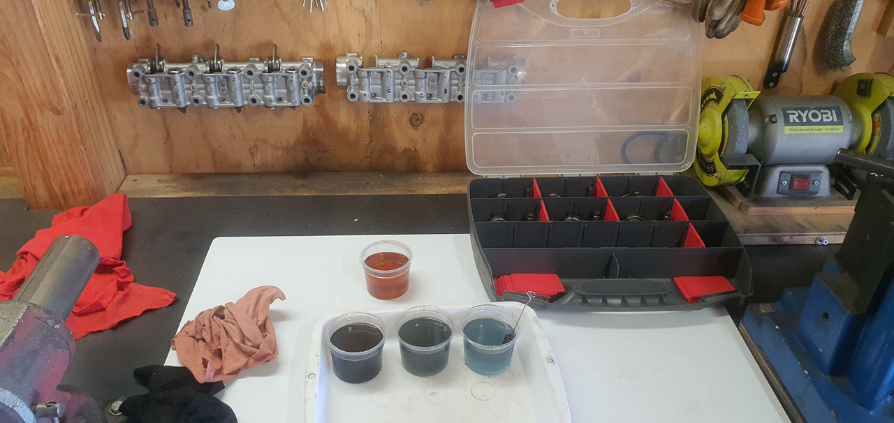
The adjusters were now all clean, lubed and showing no movement when pressed, which is what is required when bled. I then cleaned the rest of the parts and reassembled. I mounted them on the wall facing up - ready for when I need to fit them to the heads.


Interesting bit of info I found whilst doing some googling on these units I discovered that the Honda Valkyrie 1500, a sort of sportier cruiser version of the touring goldwings, has apparently got slightly hotter cams. I have not found any definitive info on exactly what the difference is. More lift or duration etc. But more interesting is that they also ditch the hydraulic lash adjusters and instead use simple screw and nut type adjusters on the rockers as per many other Honda bikes. See here...


Image


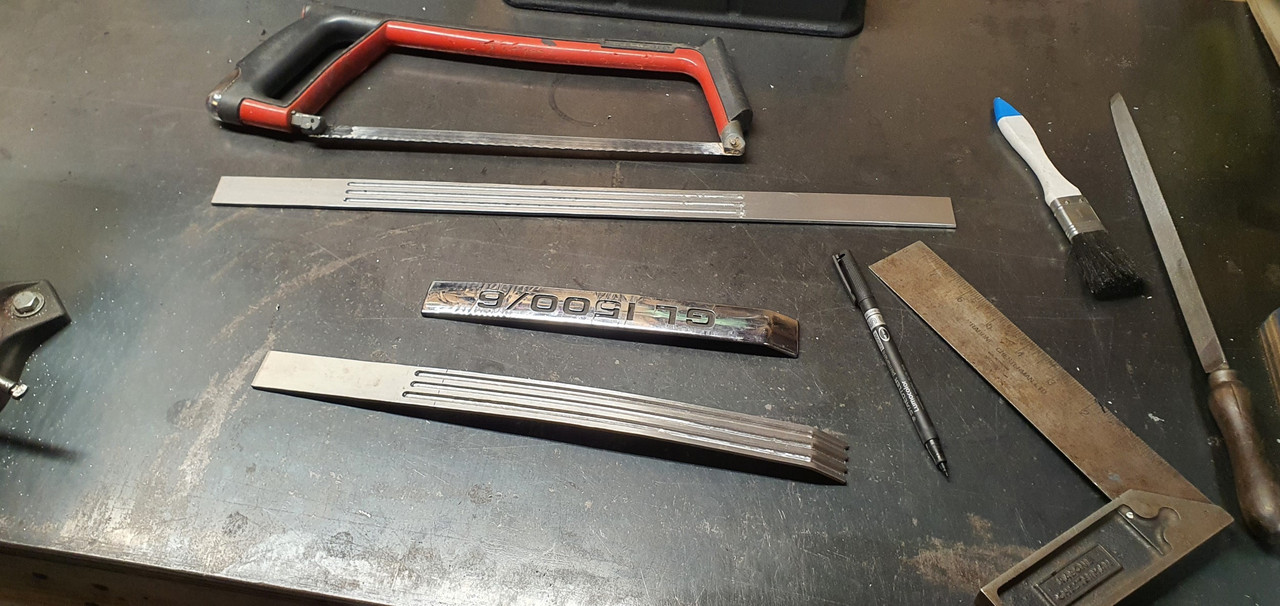
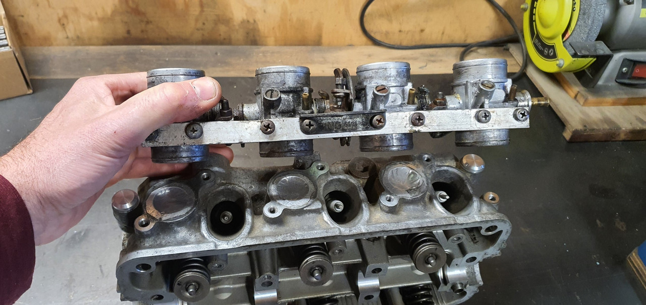
So my future plan if this engine setup works out ok would be to locate a pair of Valkyrie heads/cams/followers and have a play with them. At the same time I could setup these BMW itbs that hannah so kindly brought back from the UK...


Image


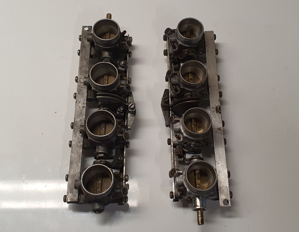
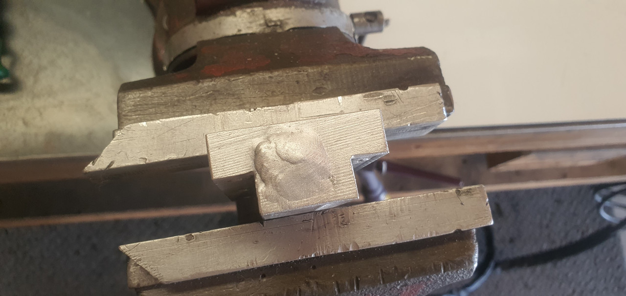
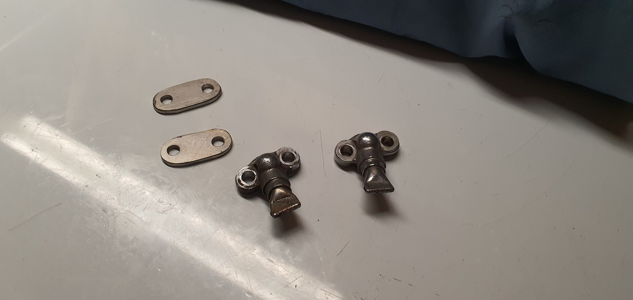
They'll need the tabs lengthening so to space them apart a touch further to suit..Image


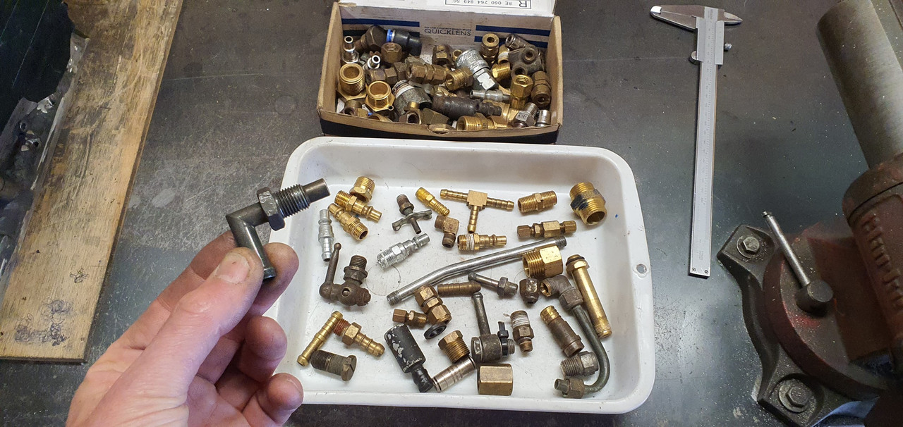
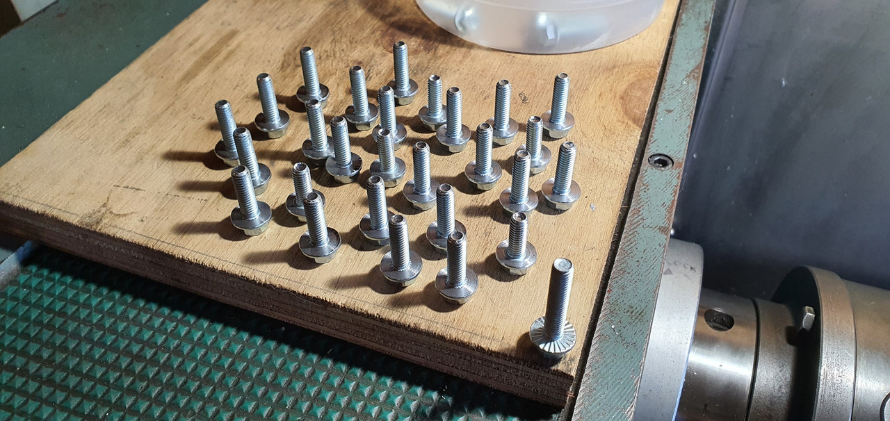
Other parts, this time delivered by the postman...


Image


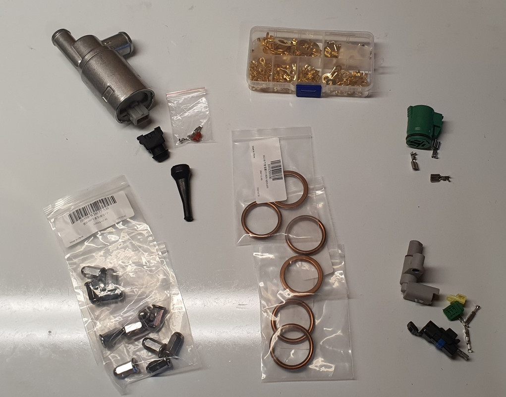
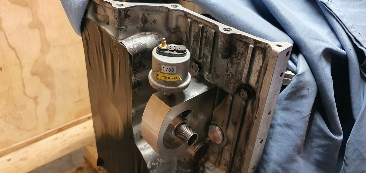
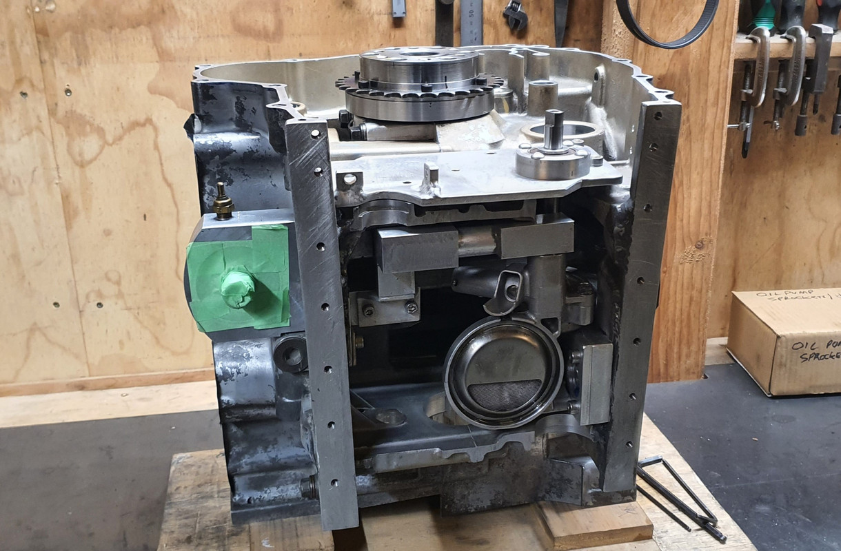
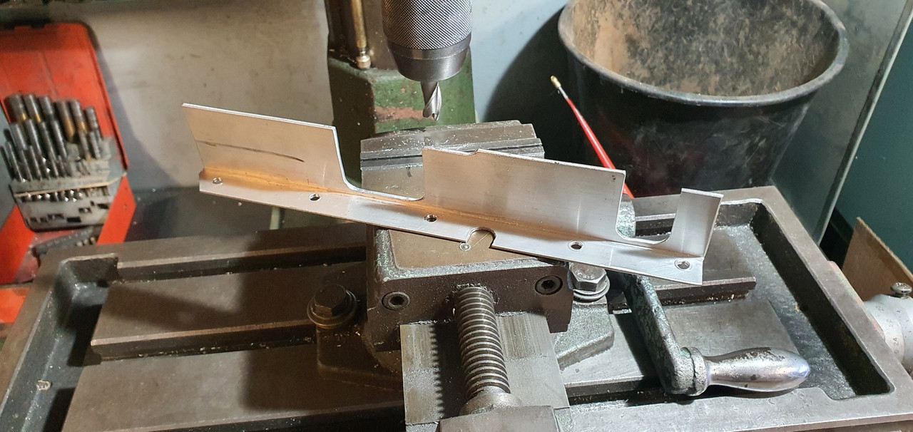
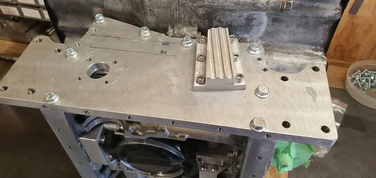
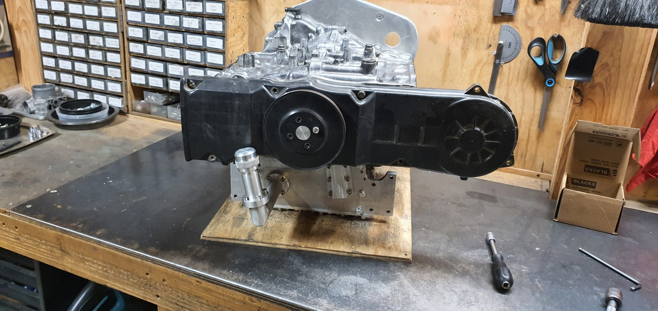
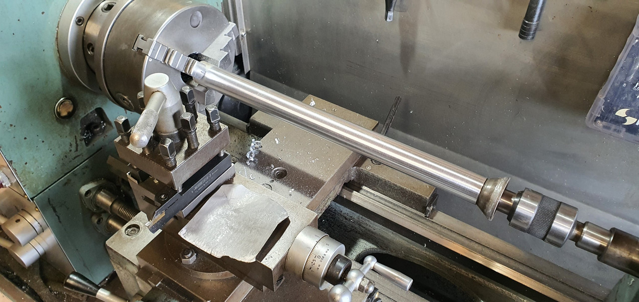
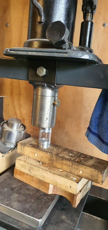
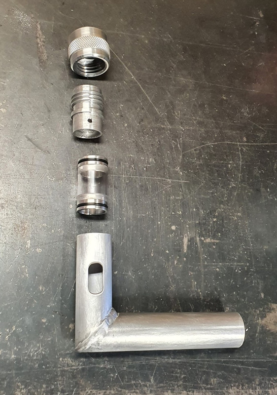
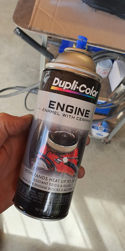
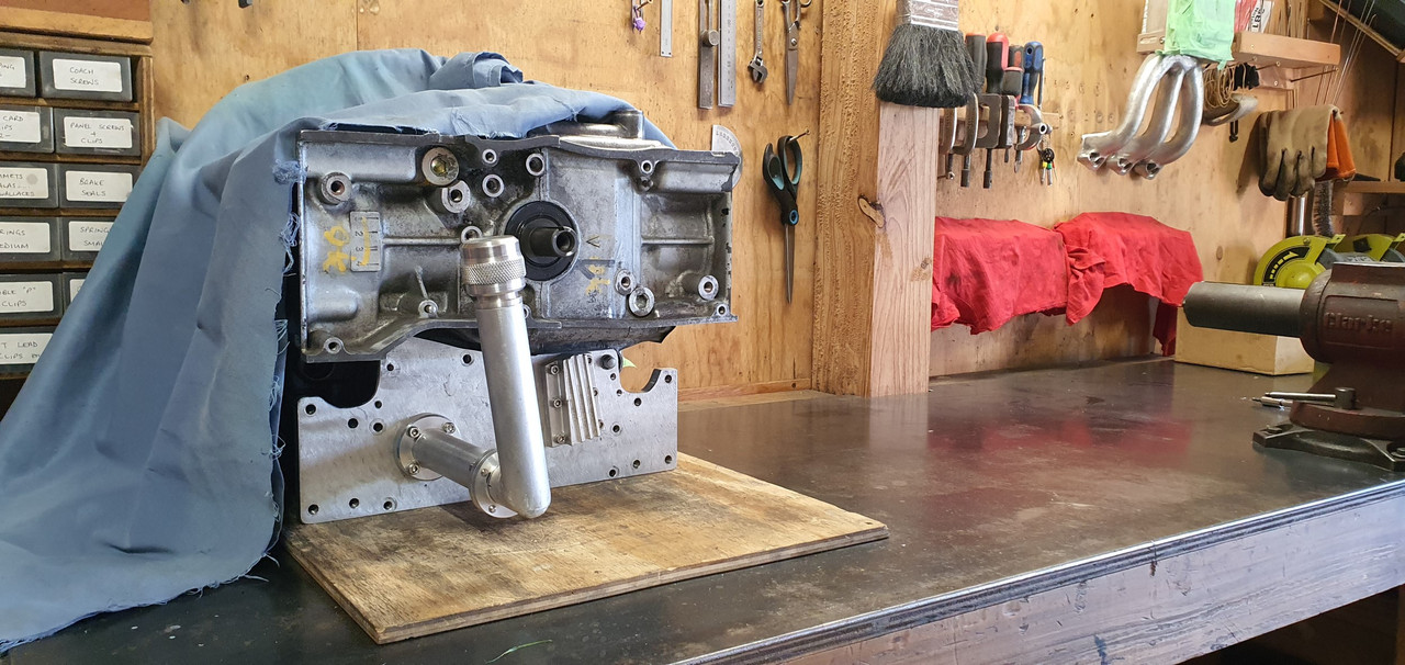
Bosch style (but not price) Idle air control valve, various sensor plugs and some shiny new exhaust gasket rings and nuts.So the heads are ready to go back on but before I do I wanted to sort some other little jobs out while the engine is compact and easy to move on the bench. This morning I made this...


Image


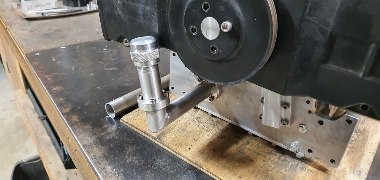
It's designed to stop oil surging back up the filler tube. It really is probably not needed actually bu I see no harm it being there as a belt and braces add on. I'e still yet to decide on the final height and extension of the filler..


Image


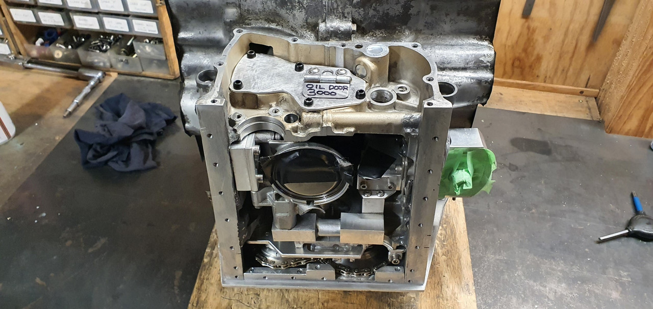
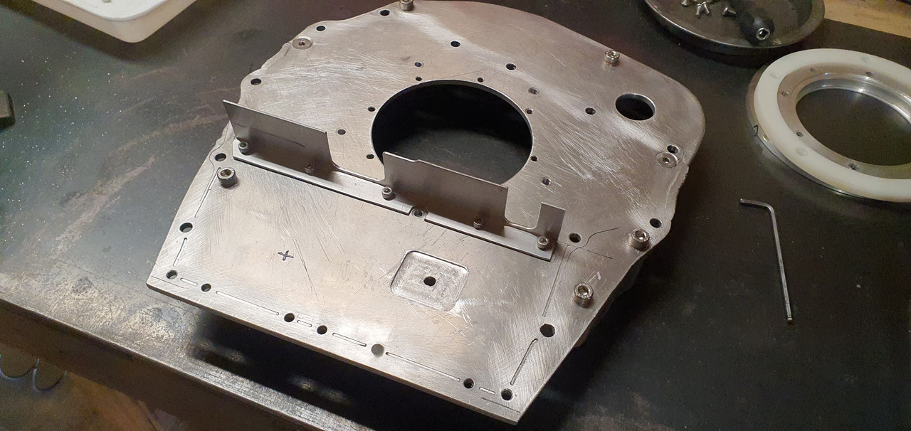
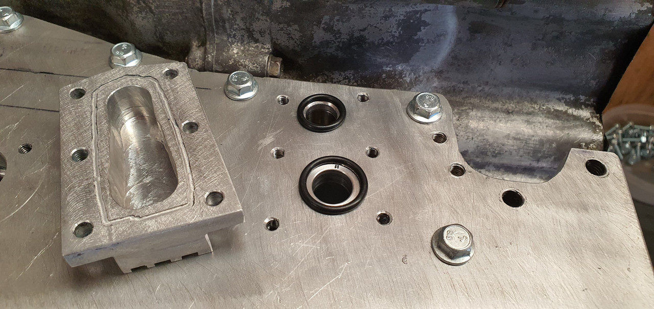
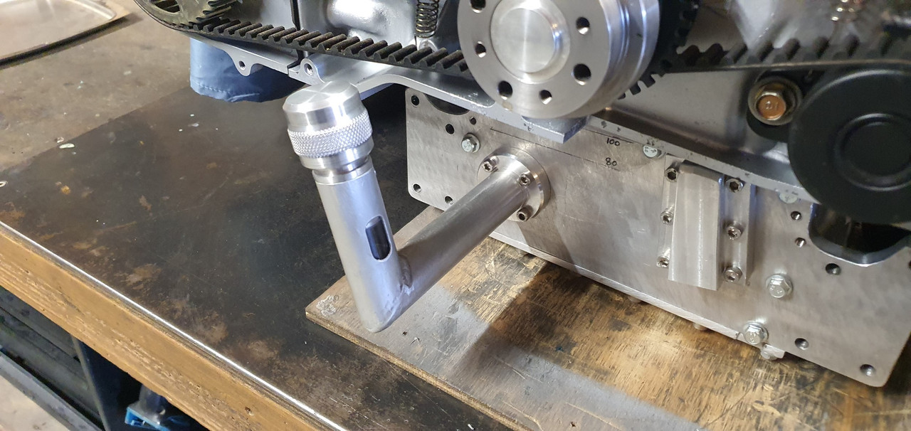
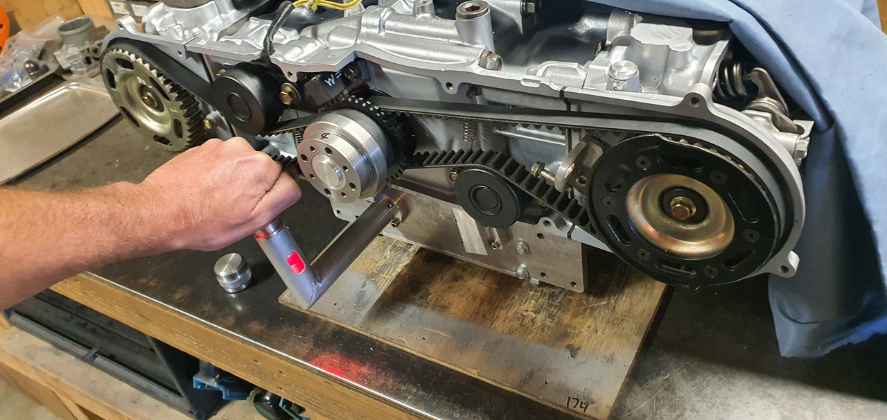
Oil height and volume is going to be more than sufficient I think. I'm not sure what the height was in the original configuration and I seem to have foolishly thrown away the original dipstick so I cant check that. Dipstick went in here..


Image


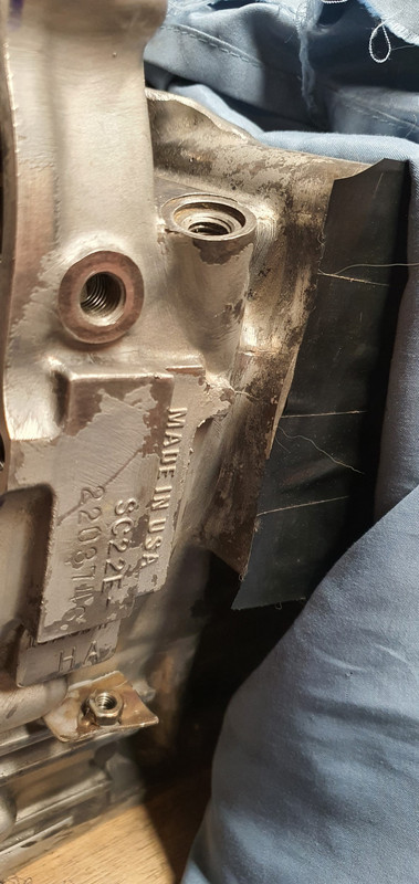
I'd like to have the oil height maybe an inch below the crank throw. I'll have a think about this. Anyway - lots of room for oil. I think about 4 litres at least.


Image


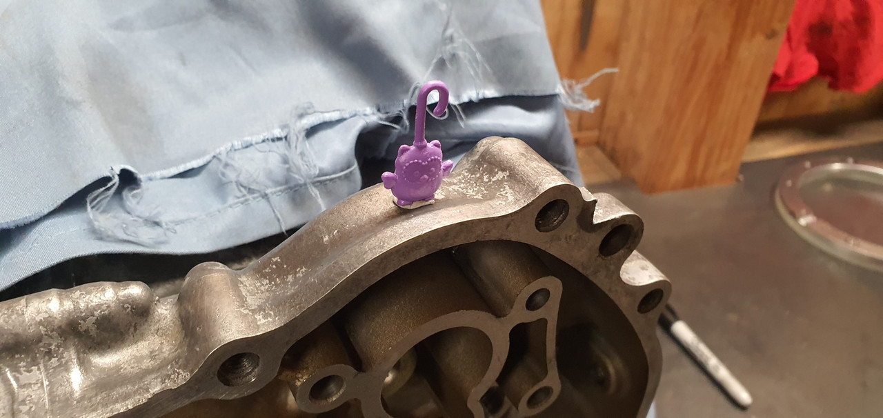
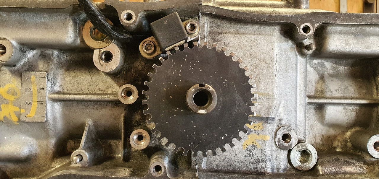
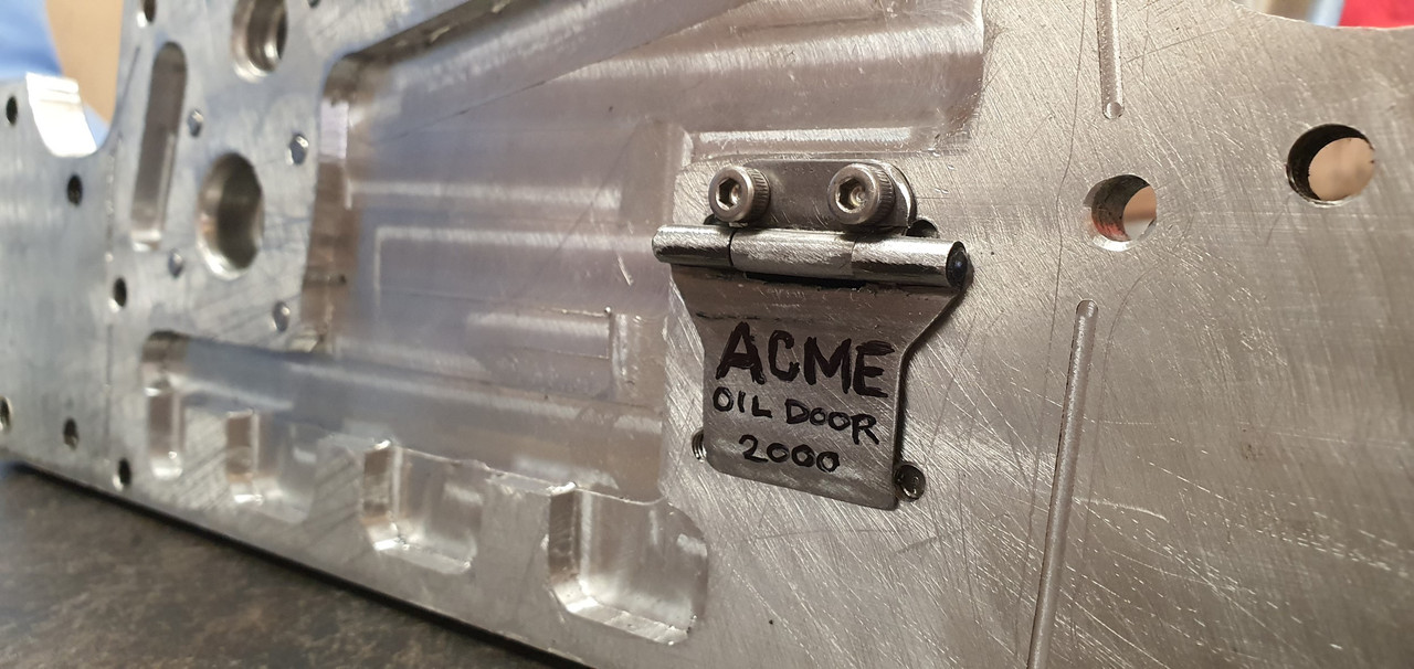
I also need to add a vent to the crankcase. Most likely it will be here, right below where the little owl is sitting...


Image


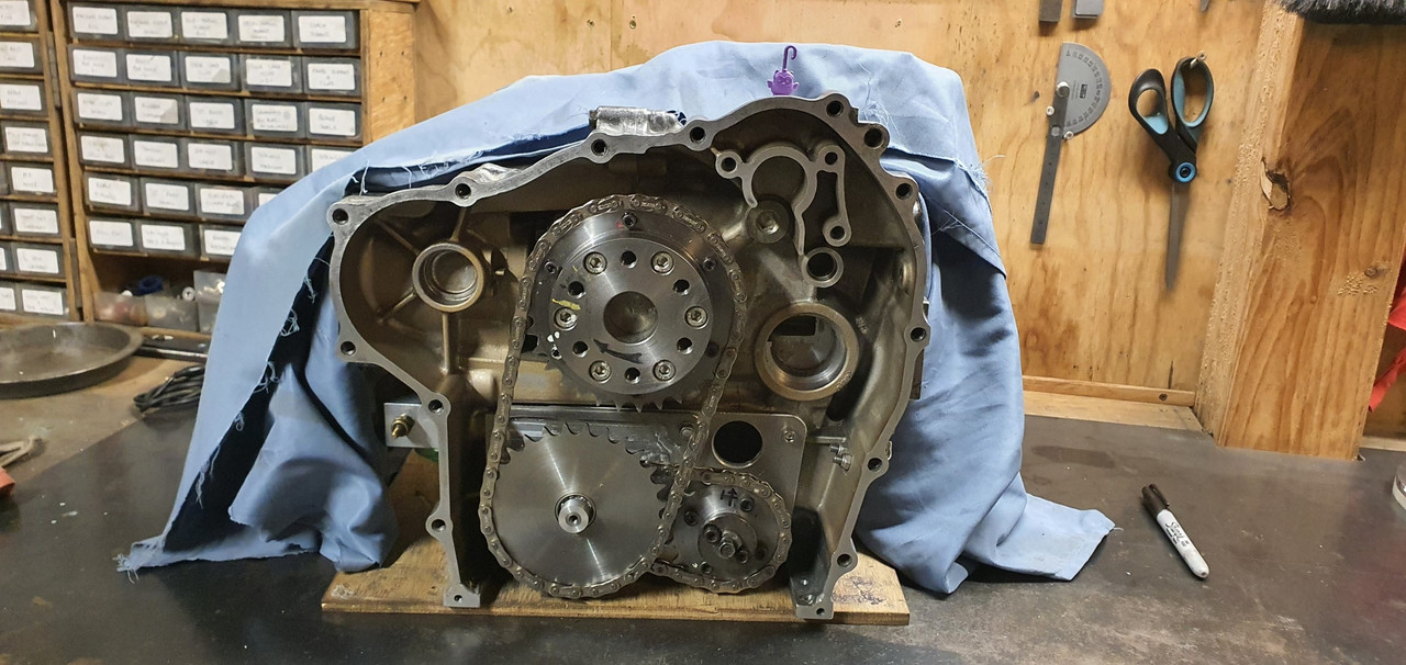
Because there is a useful casting that would shield the vent hole from oil splash..


Image
911hillclimber
Nurse, I think I need some assistance
Posts: 18924
Joined: Mon Mar 10, 2008 6:26 pm
Location: West Midlands

Re: 1965 Hillman Imp soon with flat six from a Honda

Post by 911hillclimber »

Great update as ever!
Oh so Honda the lot of it, nothing excessive, everything just right.
Anyway, after some serious 'back in the day' thinking, all my British cars leaked...I was going to tell you off, but you just may be right! :lol:
73T 911 Coupe, road/hillclimber 3.2L
Lola t 492 / 3.2 hillclimb racer
Boxster 987 Gen II 2.9
yoeddynz
DDK Fanatic
Posts: 54
Joined: Wed Feb 01, 2023 9:02 am

Re: 1965 Hillman Imp soon with flat six from a Honda

Post by yoeddynz »

The force is strong in the English car. Even when I've fitted a modern mazda V6 to my Viva it leaked, as did the mazda rotary in my Chevette :?
yoeddynz
DDK Fanatic
Posts: 54
Joined: Wed Feb 01, 2023 9:02 am

Re: 1965 Hillman Imp soon with flat six from a Honda

Post by yoeddynz »

I've not done as much on this project as I'd hoped recently but still chipping away at it.

Crankcase ventilation is sorted. I had a rummage through my box of fittings and found a suitable vent pipe thingee...

Image

Into the lathe and with a tiny boring bar I was able to reach in to machine the hub down to a neater size...

Image

Covered the vital bits to avoid swarf getting in the works then drilled and tapped a hole to suit..

Image

Drilled two drain holes to avoid any build up of of oil accumulating..

Image

Next jobs in line were to add some extra baffles to help stop oil surge. Remember a while back I had put many bits through a Jenny Craig program in a bid to make them lighter. Well I realised I should have left this plate at its full fat weight and not added this big hole which will let oil surge too easily...

Image

Silly me. Now I had to fill that hole and I was damned if I was going to disassemble all that lot to do it. So machined up a plug, as light as I could but still heavier than the material I had removed in the first place. Oh well..

Image

I also wanted to stop oil flowing out of this area under heavy braking so I made another flap. I now have two flaps.

Image

I machined up a bit of alloy angle..

Image

It was bolted here...

Image

In a similar fashion to the 'oil door 3000' its purpose is to help stop oil wafting up the back of the bellhousing plate under heavy braking. Content with the sump baffling situation I could now start sealing and bolting the plates in place. I bolted the backup thrust bearing mount in place on the bell housing and then the bell housing was bolted up to the block..

Image

The thrust bearing was bolted up..

Image

The engine mount plate was then bolted up. I had bought a load of flange bolts for this and the sump but they had serrations under the heads which I had to machine off first..

Image

Plate bolted up well. Now to connect the last bit of pipework for the oil system. But I wasn't really happy with my transfer port block sealing arrangement. This thing here...

Image

I had designed it to seal with sealant, held in place with a sealant groove.

But picturing the sealant being squished inwards towards the holes started the paranoid cogs in my brain turning. Yes it forms a nice neat bead and its pretty strong stuff but the thought of possibly having a tiny bit get dislodged in time and finding its way into the oil way to potentially block the crank feed did not impress me. So I decided on a change of design using O rings...

Image

I cut a big lump of alloy off some stock...

Image

Cut that down and machined it..

Image

Did some very careful measuring, marking and setting it up in the four jaw chuck so I could machine some oil ways and O ring grooves..

Image

Image

Image

Sealed the end of the transfer port with a plug and welded it in..

Image

Bolted it up and I'm now able to sleep again.

More holes to seal. There were two remaining air injection ports to seal up, one on each head and getting rid of these ugly lumps of metal. I cut and drilled some stainless plate to suit...

Image

Image

Much better.

Another little job ticked off was the sump plug magnet. I drilled into the stainless plug just deep enough to fit a very powerful tiny magnet I'd found on a keyfob thing..

Image

Image

Epoxied in place..

Image

Continuing on with all things oil I shortened the oil filler neck to a height I was happy with.

Image

I'm now trying to decide on how best to possibly add a little sight window into the tube. The flange I had made to allow the filler neck to be removed so the cambelt cover can be removed easier is possibly not needed any more with the neck being so short. The planned oil level is also at or just above the flange join thereabouts. I'm going to have a think about this aspect a little more before I commit to final epoxying of the bits together. Luckily its all easily unbolted so I can be changed anytime in the future anyway.

Image
User avatar
KS
Nurse, I think I need some assistance
Posts: 14947
Joined: Fri May 07, 2004 3:12 pm
Location: Cornwall

Re: 1965 Hillman Imp soon with flat six from a Honda

Post by KS »

I feel humbled by your expertise! Amazing - and fascinating in equal measure.
Keith Seume
Follow on Instagram @orange914
My YouTube channel
911hillclimber
Nurse, I think I need some assistance
Posts: 18924
Joined: Mon Mar 10, 2008 6:26 pm
Location: West Midlands

Re: 1965 Hillman Imp soon with flat six from a Honda

Post by 911hillclimber »

Lovely stuff.
With the right type of machinery all manner of possibilities open up!
Keep your focus on this, we are all hungry for updates. :)
73T 911 Coupe, road/hillclimber 3.2L
Lola t 492 / 3.2 hillclimb racer
Boxster 987 Gen II 2.9
User avatar
PeterK
DDK rules my life!
Posts: 1069
Joined: Mon Sep 01, 2014 3:04 pm
Location: GU51 - Fleet, Hampshire, UK

Re: 1965 Hillman Imp soon with flat six from a Honda

Post by PeterK »

Enjoying your attention to the detail here
'79 Targa - restoration now mainly complete & being driven
viewtopic.php?f=28&t=59756
yoeddynz
DDK Fanatic
Posts: 54
Joined: Wed Feb 01, 2023 9:02 am

Re: 1965 Hillman Imp soon with flat six from a Honda

Post by yoeddynz »

Cheers fellas.

So where I left off last time was the oil filler pipe and sight window ideas. I don't really need a separate flange now I have decided to run the pipe shorter in height. So I dug out another old bit of alloy, gave a it a clean in the lather and welded up a new pipe..

Image

Image

Image

While in Nelson city a week or so ago I popped into a plastic place that told me on the phone they had 25mm thick walled acrylic tube. Turned out they didn't and instead I left with some thin walled lexan (polycarbonate) tube, closer to 25.4 in size. It was cheap so I thought it gives me something to play with. I picked up some thin 25mm O-rings on the way home and started to suss out a way I could make it work.

The plastic was way too thin to machine Oring grooves into so instead I machined some alloy ends with grooves.

Image

I pressed the plastic onto these..

Cut a short length of plastic tube to suit..

Image

Which was pressed onto the end caps..

Image

I milled a window into the side of the filler pipe. Now I had some bits to assemble..

Image

Fitted in place..

Image

The bottom of the stub which the filler cap screws onto is pretty much at 100mm oil height. Bottom of the sight is 80mm. So if I aim for a 90mm height I'm smack in the middle.

Some led keychain trinkets turned up in the mail from China and I have a metal 'momentarily on' switch from Jaycar electronics. I'll have a play about and see if I can make a neat enough attempt fitting it within the filler cap so it does something like this (using a bike light)...

Image

Back to proper jobs now. Painting and finish assembly. First though I wanted to check the TDC marks are correct and make some timing marks to suit on my alternator pulley. I set a DTI up and found TDC. Luckily it seems the factor marks are bang on.

Image

Image

Image

Paint time.

I had bought some paint for the engine a while ago. I gave the block and heads one last clean and masked them up.

Image

Primer first..

Image

Then top coat. I decided on alloy finish, similar to the original colour. Really just too tidy it up and stop the alloy getting that annoying light corrosion.

Image

Image

Then that fun job of removing masking tape to reveal a neat finish..

Image

I masked over the original hand painted OK checks - just because I like them.

Image

Engine painted I dug out the brand new head gaskets Id bought very early on...

Image

Torqued the heads in place and then moved onto the camshafts/camshaft and follower housings..

Image

In place...

Image

Now I needed to finish the trigger wheels. Phasing them in the right place.

I laid out all the bits that go with the cam covers and pulleys.

Image

This alloy bit was damaged from when the original Goldwing bike must have been dropped (I think the engine must have come from a low mileage bike that had been involved in an accident many moons ago)

Image

It wasn't sitting flat and needed a bit of a straighten..

Image

Simple I thought. I'll use the press. I carefully set it up on the press with various bit of metal so I could bend it back straight. I got it pretty good - but it needed just a little bit more...

Bang!

Image

Whoops.

* Pic is taken after I'd already started prepping it to weld.

I preheated it in the oven and then carefully sticthed it back together. Not the nicest casting to weld but it turned out ok and luckily the repairs are not on display..

Image

Welded both sides..

Image

Trigger wheel time. First off I wanted to work out the wire polarity on the oem goldwing VR sensors..

Image

Now I knew the timing marks are good I set up the main crank position trigger wheel in place and marked it. Then welded a stub of steel in place which was cut down to form a key that locates in the cranks keyway.

Image

Image

I doubled checked the megasquirt MS extra build manual and removed the appropriate tooth so creating a 36 - 1 trigger wheel with a 50 degree offset.

Then I fitted the brand new Gates cambelts I had also bought ages ago. Sadly I discovered they are English made which means they'll probably leak..

Image

Now I could setup the camshaft position sensor trigger wheel - needed so I can run the injection mode as fully sequential.

I had made this wheel a while back but had not yet removed the half moon of material. Annoyingly I forgot to weigh the wheel before I removed material. I now had no real accurate way of working out what to mill off the opposite side to balance the wheel out. Balancing it is probably not super critical but considering that at 6000rpm this wheel will be doing 3000 rpm I really wanted to avoid any extra throw out stress on the pulley or camshaft/camshaft bearings.

The final nail in the coffin for this wheel was it slipping in my makeshift rotary table (actually just the mill vice which can be rotated to mill the concentric slot - which I did by hand)

Image

It slipped, the end mill grabbed and became two pieces with a loud bang.

Image

So I made a new wheel. This time I weighed it before removing the halfmoon. Then I was able to mill the exact right amount off to balance it as best I could.

Image

Weighing it before milling out the final weight reduction slots..

Image

Setup in place..

Image

Image

All that sorted I could move on to a fun little job I was looking forward to. Painting the cam covers and sorting out replacements for the old badges.

Image

Image

After a really good clean and some light sanding of the covers, which have been through the wars and have extensive welding repairs due to the same crash I guess, I laid down some primer.

Image

See one repair here...

Image

Due to the fairly rough finish I decided on wrinkle finish paint because it can hide sins and blemishes. I've used this same product to good success on that Mazda V6 I had plonked into my Viva HB so I was pretty confident on getting an OK finish. Covers were warmed up in the sunshine and 3 thick coats were laid down, 5 minutes between each coat.

Image

Once the paint did its magic thing they came up ok. I'm happy.

Image

Now the badges. I was going to try a couple of mates about getting something with the word HONDA 3d printed or machined in alloy but I really wanted to do it all myself and thought about some nice machined ribs to insert.

Image

they turned out neat..

Image

Carefully fixed in place as per original badges with double sided foam tape...

Image

Covers bolted up in place. I'm really happy with the look :)

Image

Image
911hillclimber
Nurse, I think I need some assistance
Posts: 18924
Joined: Mon Mar 10, 2008 6:26 pm
Location: West Midlands

Re: 1965 Hillman Imp soon with flat six from a Honda

Post by 911hillclimber »

Good going indeed, great to see such progress! :)
73T 911 Coupe, road/hillclimber 3.2L
Lola t 492 / 3.2 hillclimb racer
Boxster 987 Gen II 2.9
Post Reply