1965 Hillman Imp soon with flat six from a Honda

The place to post images of your other cars.

Moderator: Bootsy

sladey
Nurse, I think I need some assistance
Posts: 8729
Joined: Sat Apr 23, 2005 9:08 pm
Location: Nottingham, UK

Re: 1965 Hillman Imp soon with flat six from a Honda

Post by sladey »

Wowza

Impressive work - fantastic stuff - keep it coming
The simple things you see are all complicated
I look pretty young but I'm just backdated yeah
911hillclimber
Nurse, I think I need some assistance
Posts: 18924
Joined: Mon Mar 10, 2008 6:26 pm
Location: West Midlands

Re: 1965 Hillman Imp soon with flat six from a Honda

Post by 911hillclimber »

That's more like it!
Just where have you been swanning about on a push bike when there is SO MUCH to do and post on this forum!! :)

Great up-date. Envey you the miller/driller, one piece of kit i would dearly love to have, but no space in my garage 1/2 the size of yours.

Keep on going. Hope it rains some more to 'trap' you in the garage. :lol:
73T 911 Coupe, road/hillclimber 3.2L
Lola t 492 / 3.2 hillclimb racer
Boxster 987 Gen II 2.9
yoeddynz
DDK Fanatic
Posts: 54
Joined: Wed Feb 01, 2023 9:02 am

Re: 1965 Hillman Imp soon with flat six from a Honda

Post by yoeddynz »

Thanks fellas!
@911hillclimber yeah its a handy little mill. We could probably make space for a larger mill but really, at this point in time the little drill mill is useful enough and I enjoy having plenty of clear space within the workshop.

As for the cycling - its my number one passion so its a easy choice. But while out riding I find its a great space to think about solutions to problems and come up with various ideas.
neilbardsley
Nurse, I think I need some assistance
Posts: 7751
Joined: Mon Apr 16, 2012 4:31 pm

Re: 1965 Hillman Imp soon with flat six from a Honda

Post by neilbardsley »

Very impressive. I believe NZ must be amazing for biking.

Sent from my 22011119UY using Tapatalk

“A REMINDER. I would be grateful if those members who have borrowed bits from me in emergencies (e.g starter motor, oil cooler, etc) would return them and/or contact me”. – Chris Turner RIP
yoeddynz
DDK Fanatic
Posts: 54
Joined: Wed Feb 01, 2023 9:02 am

Re: 1965 Hillman Imp soon with flat six from a Honda

Post by yoeddynz »

Cam phase wheel continued. I needed a nice solid accurate hub to mount it on for machining the slots. Found a suitable chunk on the rack and turned it down to suit.

Image

Drilled and tapped a hole in the middle then machined a solid cap which is pulled down tight so holding the disc in place..

Image

Using the cam pulley as a template I scribed the outlines of the slots in place. Then into the mill and made lots of mess. Because I don't (yet) have a rotating table for the mill the slots are straight, not curved. But being short in length and even they look ok. Good enough to knock a little weight off.

Image

Image

I'll leave the final machining until just before assembly in case something changes with the sensor although I think that's pretty much sorted as I have a brand new sensor as used in many Peugeot/Citreon/fiats plus the ever helpful Chris had picked me up another one plus some various plugs I needed from pick-a-part.

I have been accumulating various plugs and terminals from Aliexpress in my quest to be able to make a new engine loom without having to splice wires to connector pigtails.

This arrived in the mail from friendly Fletch, gifted to the cause :) Its a genuine Mitsubishi ignitor for a Mitsi GTO/many other Mitsi V6 vehicles.

Image

However - its the one item I have been struggling to find the correct terminals for. They are either Yakazi or Sumitomo but I've still not found an exact match. I'll keep searching but luckily a friend James is gifting me an ignition module, exact match, plus the 3 Mitsubishi twin post coils with the leads/plugs intact between the coils and ignitor which will make for less splicing.

Another little job I checked off was to make some blanking plugs for the unused air injection ports. Not sure if they'll get painted over or left as bare alloy yet.

Image

In place but not yet fixed in. Much better than what was there (look back a post or two)

Image

Back to cooling pipes then. The extra 22mm bends I'd ordered had arrived so I could continue on with the top pipes. I found another bit of stainless tube with a gentle bend set into it.

Image

Ideal for this area...

Image

I used some of Dads old surgical forceps to hold the pipes in place while I tacked them..

Image

Now I needed to merge the pipes into a larger size so off to the press..

Image

Tacked in place and blend it in..

Image

I joined the rear pipework with merger to the front pipe assembly with a short bit of radiator hose leftover from the front of the Goldwing. The rear pipe needed a bracket. Played with bits of card until I had a shape that worked..

Image

copied it into stainless like such..

Image

That was welded in place and the top pipe assemblies were pretty much finished.

Image

You can see how they are routed in relation to the inlet manifold once its back in place. As with many aspects of the build so far I have done my best to make sure they can be easily removed and don't hinder the removal of the inlet in one piece.

I'll be adding to their length, plus the bottom pipe , once I have worked out the best positioning of the water pump but that has to wait until the engine in the back of the spare imp for mocking purposes.

Other trinkets/treats/goodies that have arrived in the mail are these universal joints..

Image

They are for the gear shifter shaft that runs under the tunnel from the transmission to the gearstick. Because the selector rod enters the Subaru gearbox a bit higher up and at a slight angle compared to the imps original transmission I need these to connect the dots. I wanted something with no slop to keep the shifter travel tight. These have sealed bearings and are aluminium so lighter than they look.

Image

This afternoon I dropped Hannah off at Nelson airport as she's off to the UK to see her family. Almost 4 weeks home alone so I'll be trying to do as much as I can on this build :)

While in Nelson I picked up another one of the same model chain that I'm using for the oil pump drive. I bought it mainly for with the special strong joining link that I needed. It wasn't looking promising to be able to get these particular links by themselves in NZ but no worries anyway as I'll need a new chain for one of my old bike restorations I'm in the process of doing so now I have one...

Image

When I got home I found this assembly in my mailbox courtesy of friend Damian.

Image

I now have a spare gearstick assembly so I can mock up and build the shifting linkage in the green Imp shell.

Next step is to finish my fuel rail inlets/outlets to suit. Then a quick wire brush of the crankcase and assembly can start. With this in mind I searched deep into my moth ridden wallet and paid the man for some of this stuff which by all accounts is the best there is..

Image
User avatar
Jonny Hart
Put a fork in me, I'm done!
Posts: 1544
Joined: Mon Feb 01, 2010 2:28 pm

Re: 1965 Hillman Imp soon with flat six from a Honda

Post by Jonny Hart »

Love this project!

I believe your 6 pin connector is Sumitomo 6189-1083. Here's the dataheet ( search for 6189-1083 in this pdf - it's on page B-06 top right). The pin will be in there too.

https://prd.sws.co.jp/components/series ... nts_je.pdf

They are horrible to crimp and if you don't get them exactly right you can't fit the slide lock, so buy a few to practice on.
911hillclimber
Nurse, I think I need some assistance
Posts: 18924
Joined: Mon Mar 10, 2008 6:26 pm
Location: West Midlands

Re: 1965 Hillman Imp soon with flat six from a Honda

Post by 911hillclimber »

The other day I was going to post a MOAN about lack of progress, but this makes up for it.
I look forward to seeing the next 4 weeks on this great little car.

I need a similar shaft UJ for my race car gear linkage as one of the 1980's helicopter joints is showing some play.
We don't have that design in the UK but the design looks very good. I suspect they are for steering applications?

Keep it coming!
73T 911 Coupe, road/hillclimber 3.2L
Lola t 492 / 3.2 hillclimb racer
Boxster 987 Gen II 2.9
yoeddynz
DDK Fanatic
Posts: 54
Joined: Wed Feb 01, 2023 9:02 am

Re: 1965 Hillman Imp soon with flat six from a Honda

Post by yoeddynz »

911hillclimber wrote: Thu Jul 27, 2023 5:03 pm We don't have that design in the UK but the design looks very good. I suspect they are for steering applications?
Yeah could be used for steering but I'd be cautious and rather than risk fatigue issues I'd got with steel units.

These were cheap on aliexpress though - about 40 quid for both inc postage. I searched for ages - its unreal what some outfits want for lesser items.
911hillclimber
Nurse, I think I need some assistance
Posts: 18924
Joined: Mon Mar 10, 2008 6:26 pm
Location: West Midlands

Re: 1965 Hillman Imp soon with flat six from a Honda

Post by 911hillclimber »

Indeed, and I've found the same joint here in the UK, £40.
Will need some boring out to match the gear shift rods on my car, but all doable.

Other makes here are north of £140/160!
73T 911 Coupe, road/hillclimber 3.2L
Lola t 492 / 3.2 hillclimb racer
Boxster 987 Gen II 2.9
yoeddynz
DDK Fanatic
Posts: 54
Joined: Wed Feb 01, 2023 9:02 am

Re: 1965 Hillman Imp soon with flat six from a Honda

Post by yoeddynz »

yep crikey - some crazy pricing that!!!!

These bits turned up thanks to friend James..

Image

Sweet. I've got some coils and a spare ignitor. but hang on a minute... something ain't quite right. One of these things is not like the other...

Image

This will give me nightmares if I fit a mismatched coil. I'll have to look about for another matching FC0021 :)

While is was looking at ignition stuff I dug out the original Goldwing coils and leads from the store room. Then this happened to them...

Image

The leads have molded rubber boots, shaped neatly to seal the spark plug holes. Three of them are perfect for the LH bank and will point the leads nicely towards the front of the car direction.

Image

At this point in time I am planning on mounting the coils up under the parcel shelf, sort of above the transmission and out of immediate view.

But the other 3 boots left over are all over the place. Only one remotely points towards the transmission.

Image

The standard leads are solid copper strands and from what I know they are not the best thing to have around electronic engine management. Maybe they are OK? I'm not 100% sure yet but what I do know is that they were too short and a bit messy looking. At the spark plug end there's a very neat little brass fitting that screws into a plastic guide inside the boot. See the bits here...

Image

The tread is m10 x 1.25. How handy. I'll get a long bolt, screw it in place, clamp the bolt head firmly in the vice and simply pull the rubber boot off the plastic insert...

Image

Poos.

I superglued it back together and put it out of sight. It'll be fine. I think I can pass 7mm silicone leads through the insert anyway when I make new leads.

I don't like the way the silly boots that refuse to point the correct way bend awkwardly. This is the best of them. Not really neat enough and I only have the one of this shape anyway.

Image

So I got a sharp knife and performed a little circumcision on one of the 2 remaining...

Image

The end tapered nicely with a flapdisc on the grinder...

Image

And looks OK in place. If I get some nice flexible leads they'll curve the way I want fine I think.

Image

Now the fuel rail fittings. I had a certain look in mind, tidy, simple and pointing the hoses where I wanted them. I machined up these bits in stainless. You can see the first one I had made and brazed already just as a trial..

Image

silver soldered them together. Not as neat as I wanted- possibly it doesn't flow so nicely on stainless? Luckily the worse bits face down.

Image

Now to get the angles just right and mark them..

Image

Then braze them in place...

Image

I'll clean them up in the morning. My plan is to paint the rails in black epoxy and leave the stainless bits clear. Hopefully they'll be tidy enough for this to work out well.

The rear inlet I have yet to decide on with regards the positioning of the hose. I'm leaning towards it heading down out of the way rather than across because I'd like to keep the area around the throttle body as clear as possible.

Image

Image

For the fuel pressure regulator outlet end on the other rail I had to first turn the end of the reg mount down. Awkward in the 4 jaw so I mounted it to a lump of alloy that I'd turned a spigot onto, so centralising the mount.

Image

Regulator can now mount here...

Image

But it just annoys me a bit that its sitting there, right over a plug hole, on view.

Luckily the home made spark plug wrench I'd made...

Image

....because I didn't have one to suit the plugs/hole size on this engine when I was stripping it down, still fits and works but would be better with a smaller diameter shank..

Image

But maybe I extend the rail with a bit of curved tube and mount the regulator sort of here...

Image

I shall ponder this and look at it tomorrow. Time to kick up my feet and do my next bit of google homework - look up leads for the ignition.
yoeddynz
DDK Fanatic
Posts: 54
Joined: Wed Feb 01, 2023 9:02 am

Re: 1965 Hillman Imp soon with flat six from a Honda

Post by yoeddynz »

I went with curved. I thought I had a 16mm/5/8" tube bender but its actually a 1/2" so instead I heated the tube up and bent it carefully...

Image

Turned out OK. Not too ovalised or squished at the bend point..

Image

Cut out a small section I needed and welded it in place. Then brazed the Nissan regulator flange on. I now have plenty of clearance around the spark plug hole and the regulator is tucked away a little more from obvious sight. The fuel hose will run neatly over the starter or possibly run it below. I'll decide this when its all being set up in the car.

Image

Image

Image

As you can see I had fitted the transmission in place and the starter so I could decide better on the positioning of things.

That rail finished I moved onto the other side. I decided I'd run the hose down. Fitted the inlet bit in place, orientated the hose where I wanted and marked it.

Image

Brazed in place...

Image

Filed the joins and tidied things up as and where I saw fit..

Image

My work area that morning..

Image

Almost getting to the reassembly of this engine :) But before I stripped it down I marked out the perimeter of the engine crank case onto the rear plate/bellhousing combo.

Image

Then I very carefully, with a teeny little slot drill, milled some sealant retention grooves between the bolt holes to a level just above the expected oil line..

Image

Now I could strip the engine. But before I took the crankcase halves apart I gave them a quick tickle with a wire wheel. I'll be painting them soon so I wanted a good smooth surface. It'll never be as smooth as a factory finish because the old paint is too chipped. But it'll look neat enough.

Image

Then finally back down to two halves...

Image

I pulled the pistons out from their storage spot for a clean. They are actually way cleaner than I remembered with really only the tops having light carbon build up.

Image

Interesting and pleasant surprise I discovered. The pistons have press fitted wrist pins. I had always been assuming they would be secured with circlips because I had been told this engine was an '88. In the first year of manufacturing of 1500s, 1988, they had circlips and then they changed to push fit (I'm hazarding a guess that they might have had some engine warranties due to adventurous circlips leaving their allotted slots? )

Image

Anyway. That's nice.

There is also one other minor change made to the engine internals around 1990ish, maybe a bit later, when they added needle roller bearings to the valve lash rockers. I'll show that in more detail when I get to it and will discover what type I have.

Back to the pistons. I've set up a little cleaning station at the bench and have been getting high on acetone.

Image

Too much fumage really - I think will leave the rest until next time and do this job outside. But they are coming up pretty sweet!

Image

After they are cleaned up I'll have to make three special piston ring compressors for the assembly of the second crank case half over its 3 pistons. More about this next time :)
911hillclimber
Nurse, I think I need some assistance
Posts: 18924
Joined: Mon Mar 10, 2008 6:26 pm
Location: West Midlands

Re: 1965 Hillman Imp soon with flat six from a Honda

Post by 911hillclimber »

This is getting good!
Love the detailed thinking and execution.
Honda engineering is really good.
73T 911 Coupe, road/hillclimber 3.2L
Lola t 492 / 3.2 hillclimb racer
Boxster 987 Gen II 2.9
yoeddynz
DDK Fanatic
Posts: 54
Joined: Wed Feb 01, 2023 9:02 am

Re: 1965 Hillman Imp soon with flat six from a Honda

Post by yoeddynz »

Yeah - this little engine seems very nicely made but with a tidy simplicity about it. I like the fact the heads and everything with them, except the camshafts, are identical. Obviously cut down manufacturing costs and makes it easier for spares etc.

Not much info out there on the web about modifying these engines though. I figure the target audience, middle aged and older blokes touring about doing huge mileages are not really interested in outright speed. Just comfort, smoothness and reliability. If I get a spare set of heads I'd love to go to town on them, get a cam grind and have a play. There's more to be had that's for sure.
yoeddynz
DDK Fanatic
Posts: 54
Joined: Wed Feb 01, 2023 9:02 am

Re: 1965 Hillman Imp soon with flat six from a Honda

Post by yoeddynz »

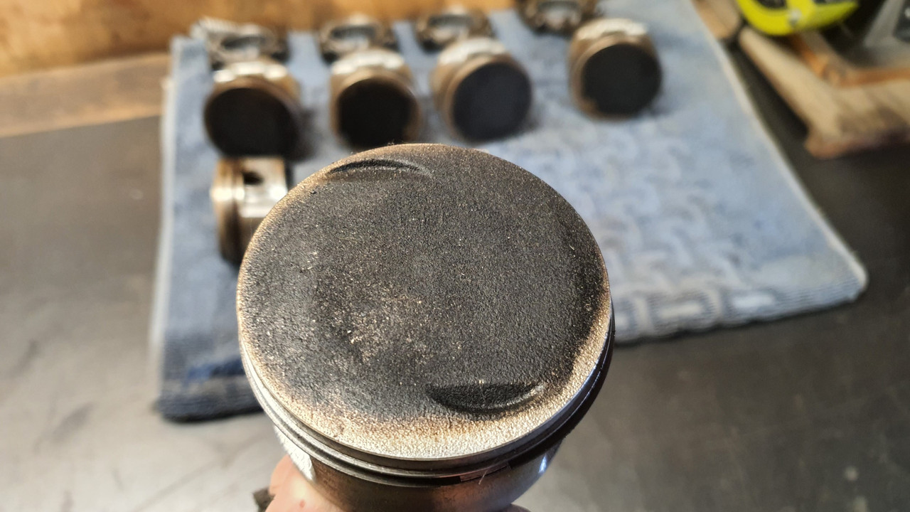
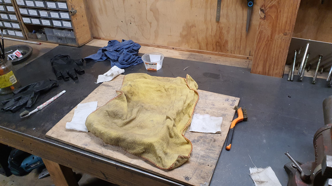
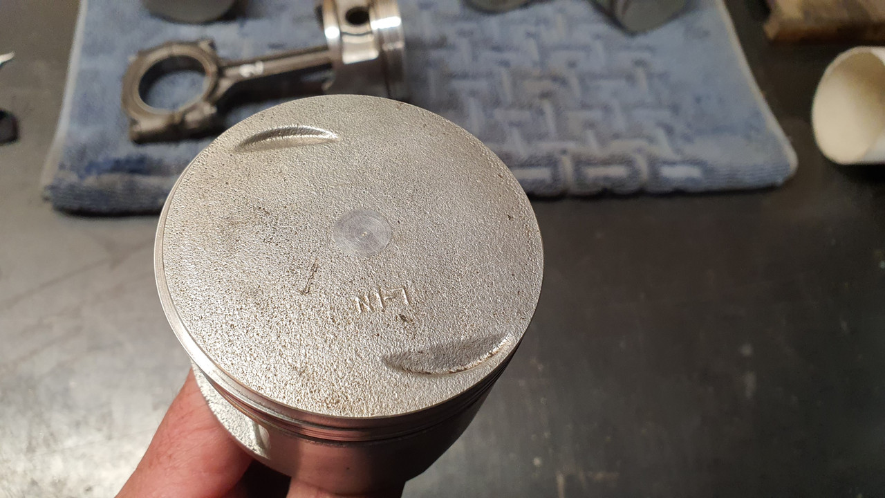
Oven cleaner. Just a tiny bit on a rag was perfect for removing the last stubborn bits of carbon staining on the pistons.

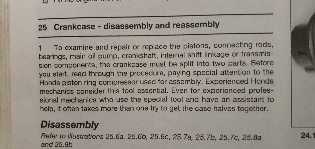
Now for the what I fear is the trickiest part of the engine assembly which is assembling the two crankcase halves together, the last half over 3 pistons. Its the bit that's if not done correctly could at worse break a piston ring. Even the one of the manuals states this...

Image

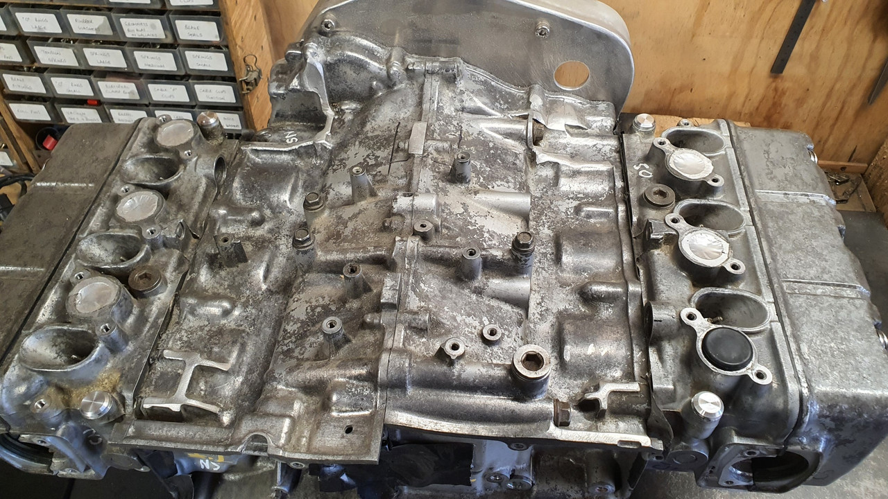
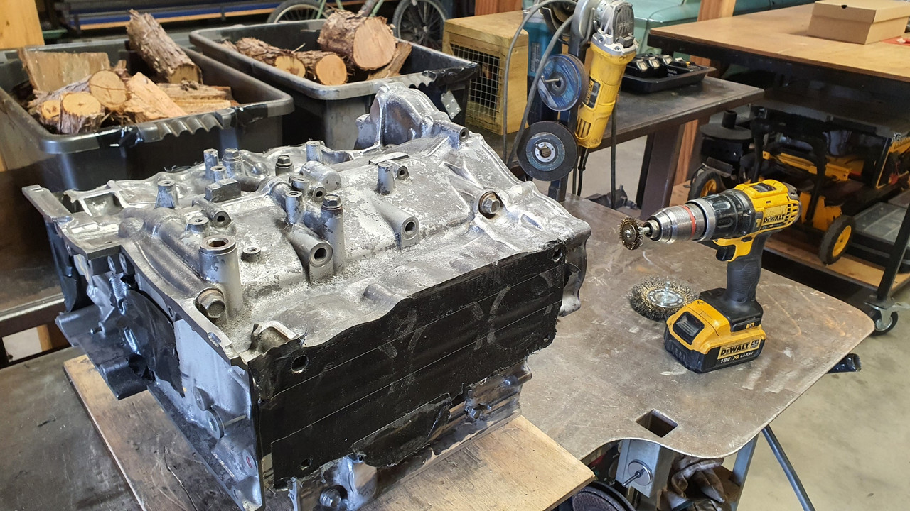
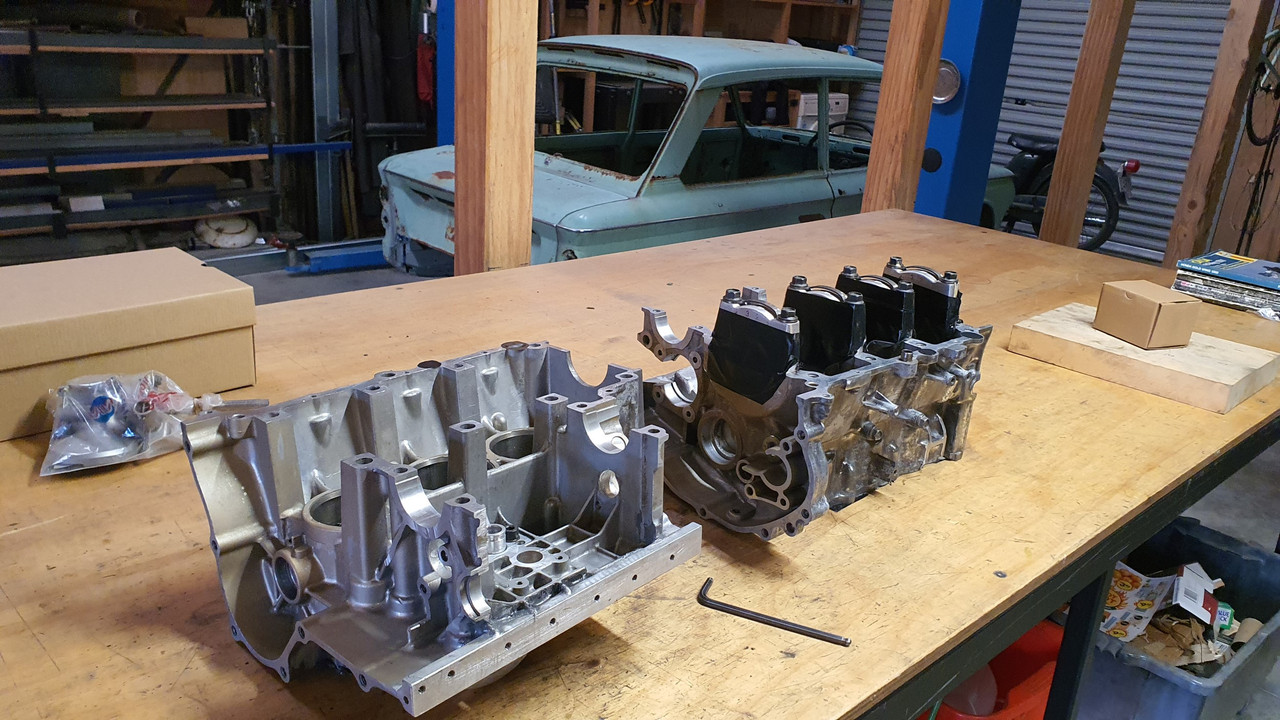
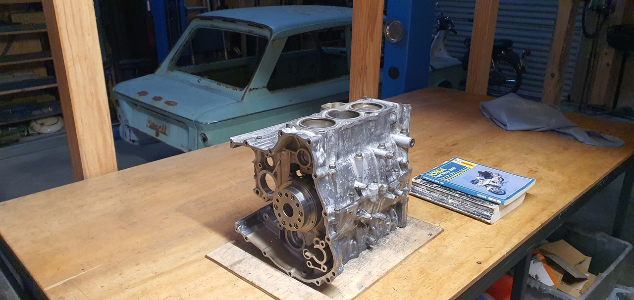
So I started the process by giving the crank case halves a nice clean over and prep.

Image

Then I got the crank out from its hidy place under the table.

Image

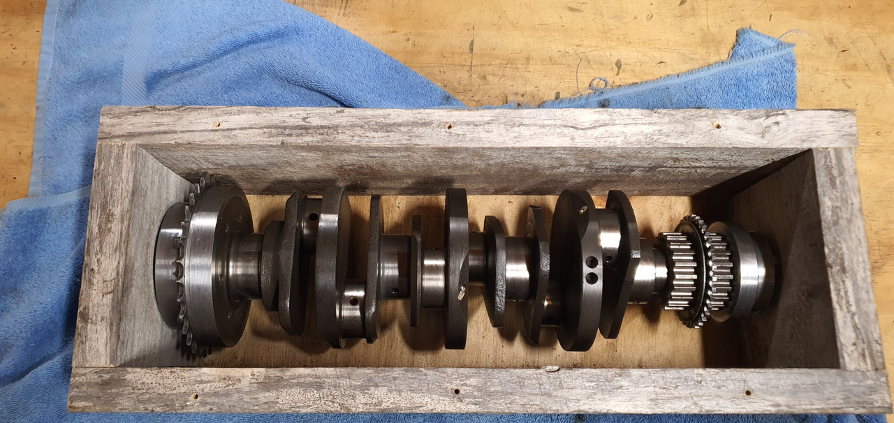
Gave it a good clean and as per advice double checked for any burrs in the oilway holes. They were spot on. Very nicely finished all over.

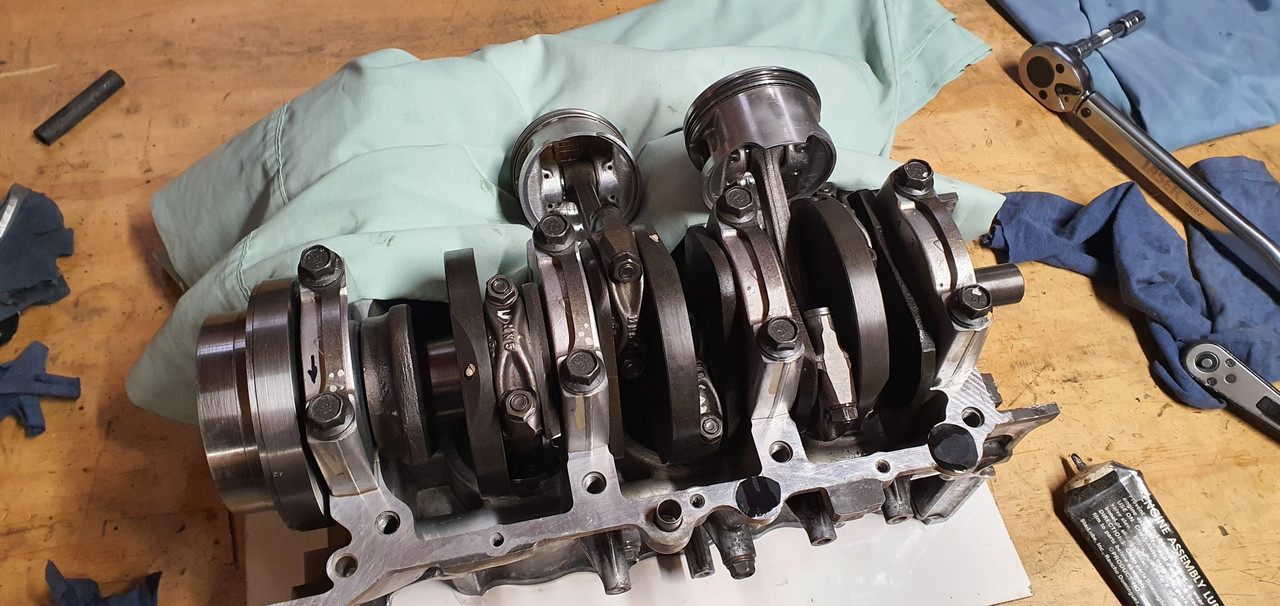
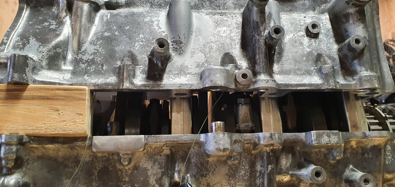
Put the crank in the hole...

Image

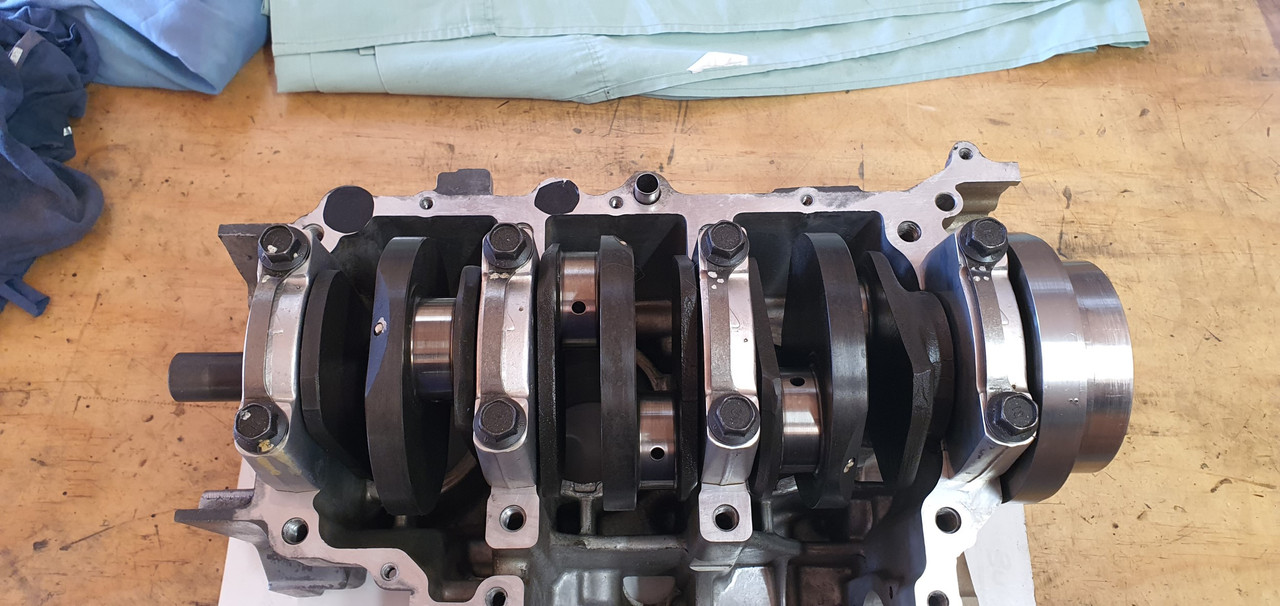
Note the smallish crank thrust washers...(edit- this is just one of them - there's another on the flywheel side but I couldn't get a pic of that one because the flywheel adaptor hub is in the way)

Image

Rotation direction aside, this is probably the engines weakest spot in terms of being used as car engine, with a manual box that is. Good quality oil with snake oil ptfe treatments and don't sit at an intersection in gear with the clutch depressed etc etc will be the name of the game :) However all is not glum because after some extensive bedtime scheming and designing I have a good idea as an extra precaution I might do.

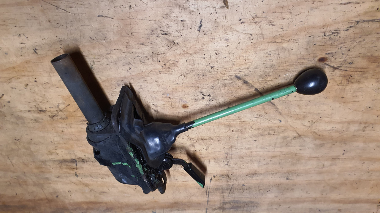
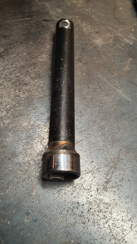
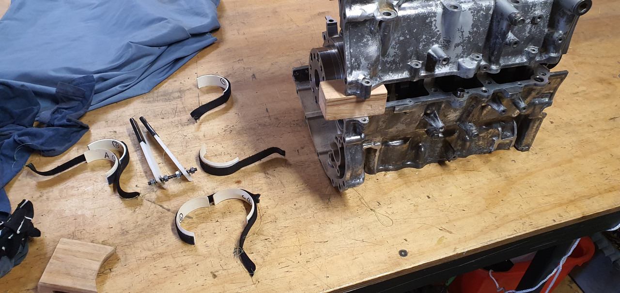
Anyway- back to the build. Now I had to make some special Goldwing specific tools. Firstly are the piston ring compressors. Here's a pic of one of the Honda items ...

Image

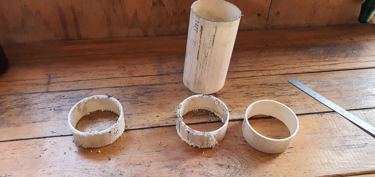
Basic and gets the job done. But expensive, especially combined with the other bits and anyway - I like to make as much as I can. I got a bit drainpipe from a local plumpers supplies. It was actually a perfect fit over the piston. Like 10 thou smaller in ID and it wouldn't have gone on. Fluke. Lady couldn't be bothered to charge me anything either :)

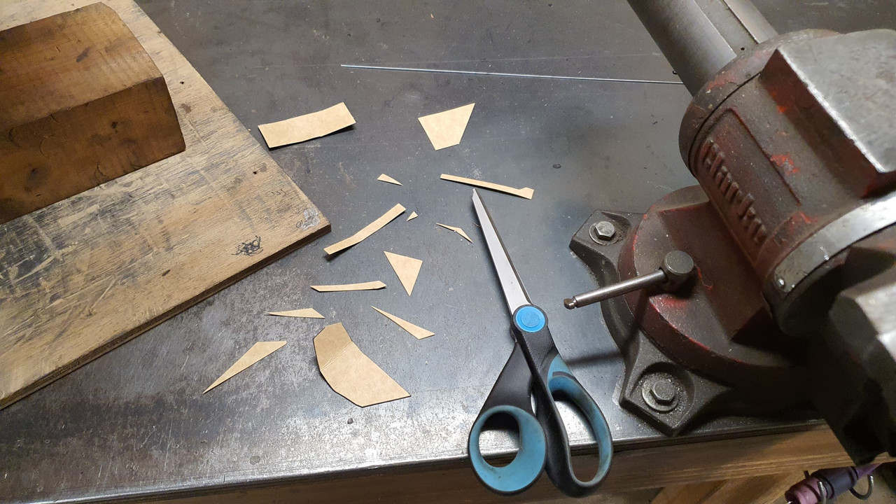
I chopped it into bits...

Image

Image

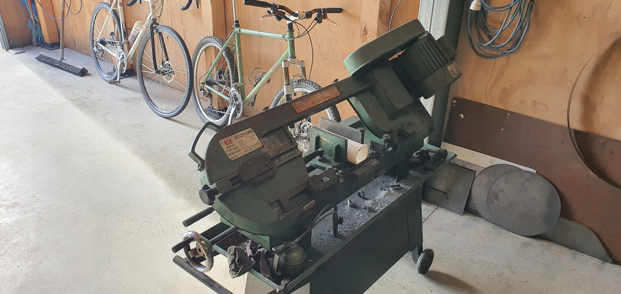
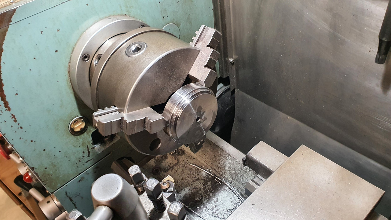
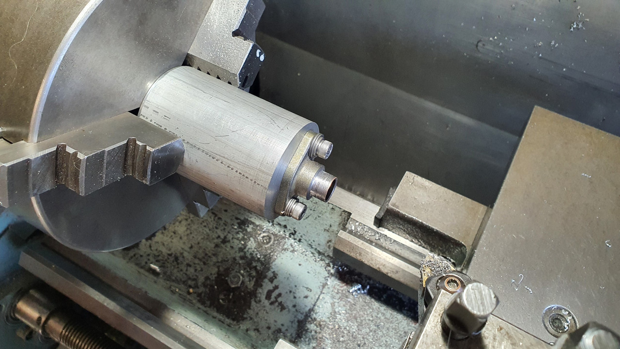
To machine such flexy plastic rings I needed a support. Luckily I had a lump of thick alloy tube leftover from removing a customers lpg setup. I skimmed it down...

Image

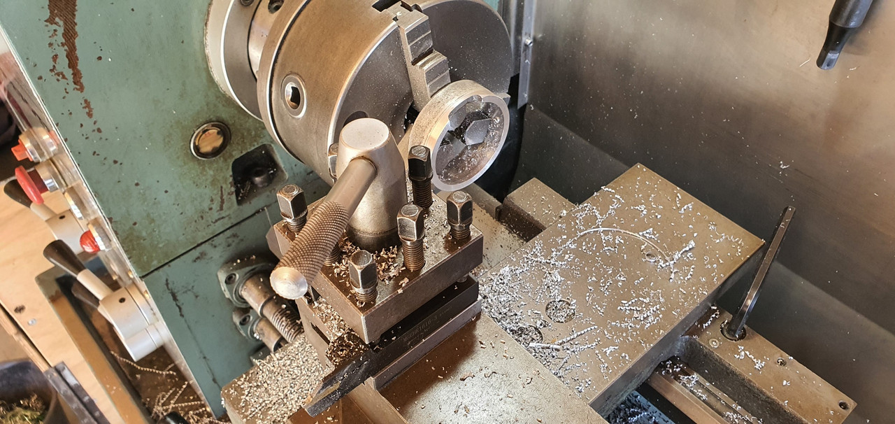
Now I could turn a taper onto the rings and make lots of plastic mess...

Image

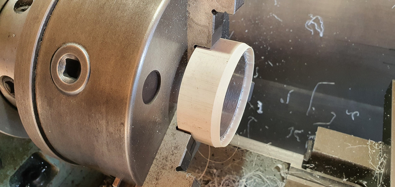
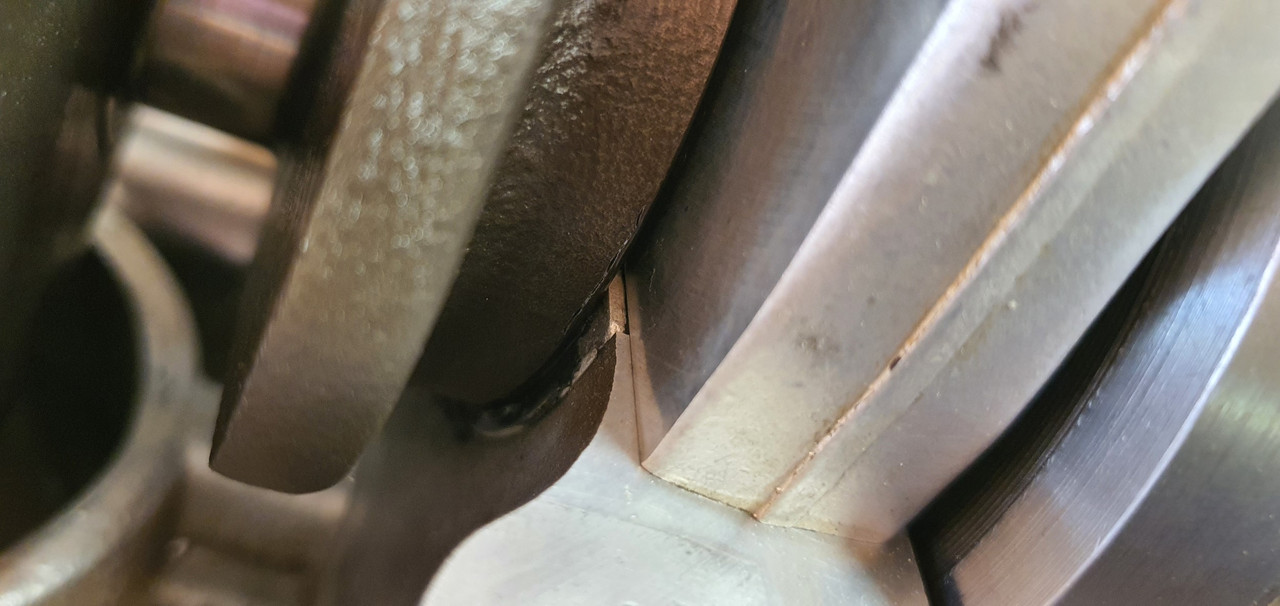
The taper locates the compressors into a tapered lead at the base of each cylinder liner on the LH case, so guiding the compressors and stopping the chance they might flex out as the case is lowered down over the pistons heads. I had to get the taper angle just right.

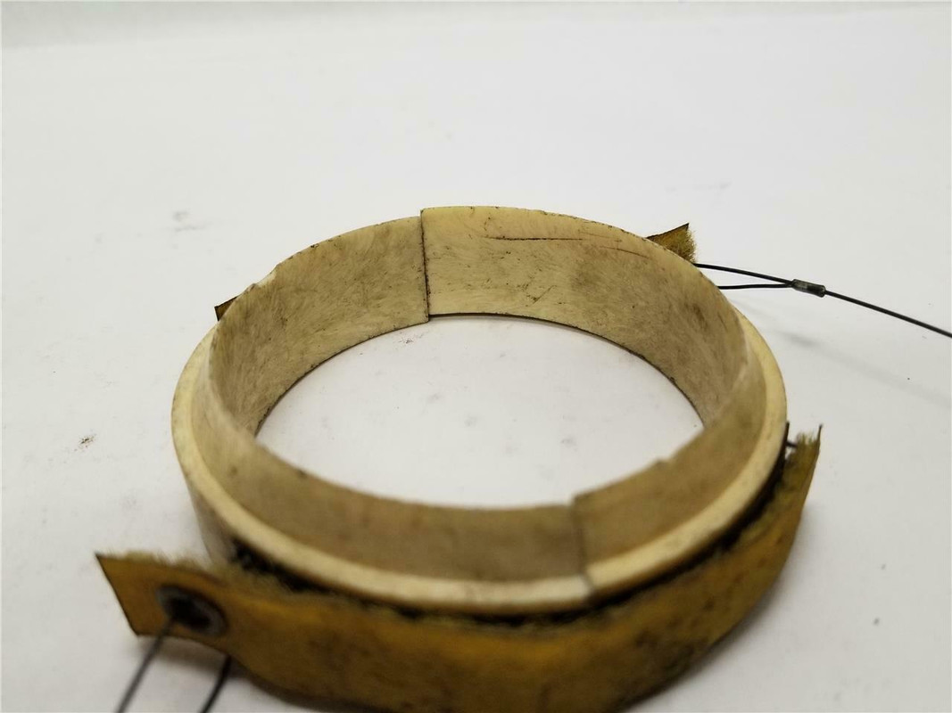
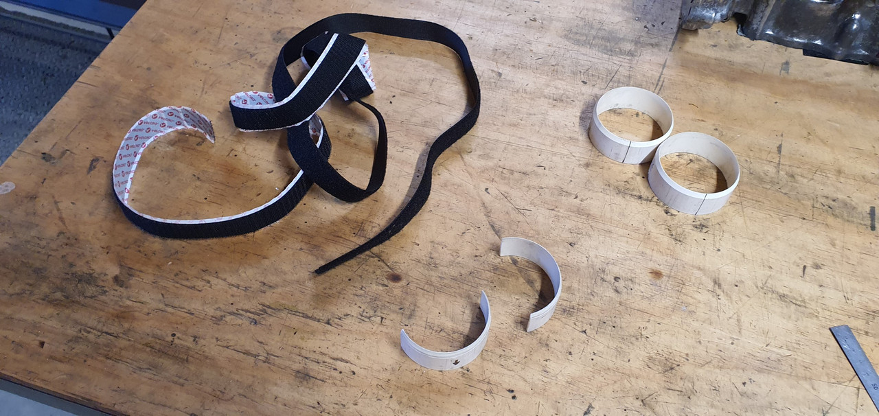
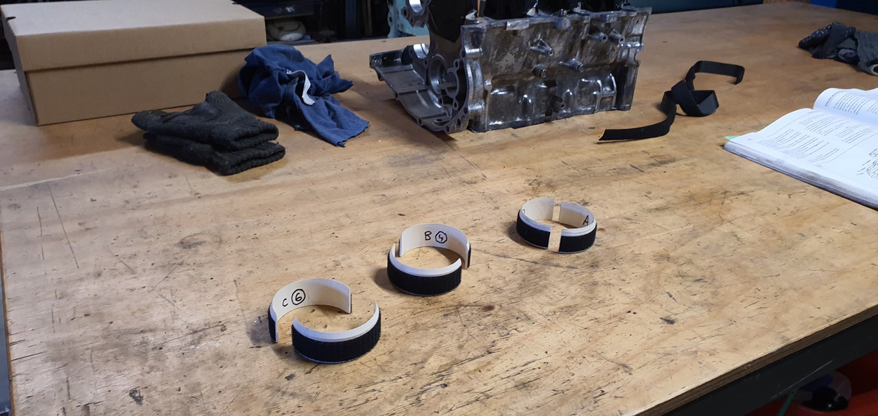
Cut each rings in two. Now for some decent quality velcro. I found a meter pack of one side sticky, the other for sewing. Perfect!

Image

Image

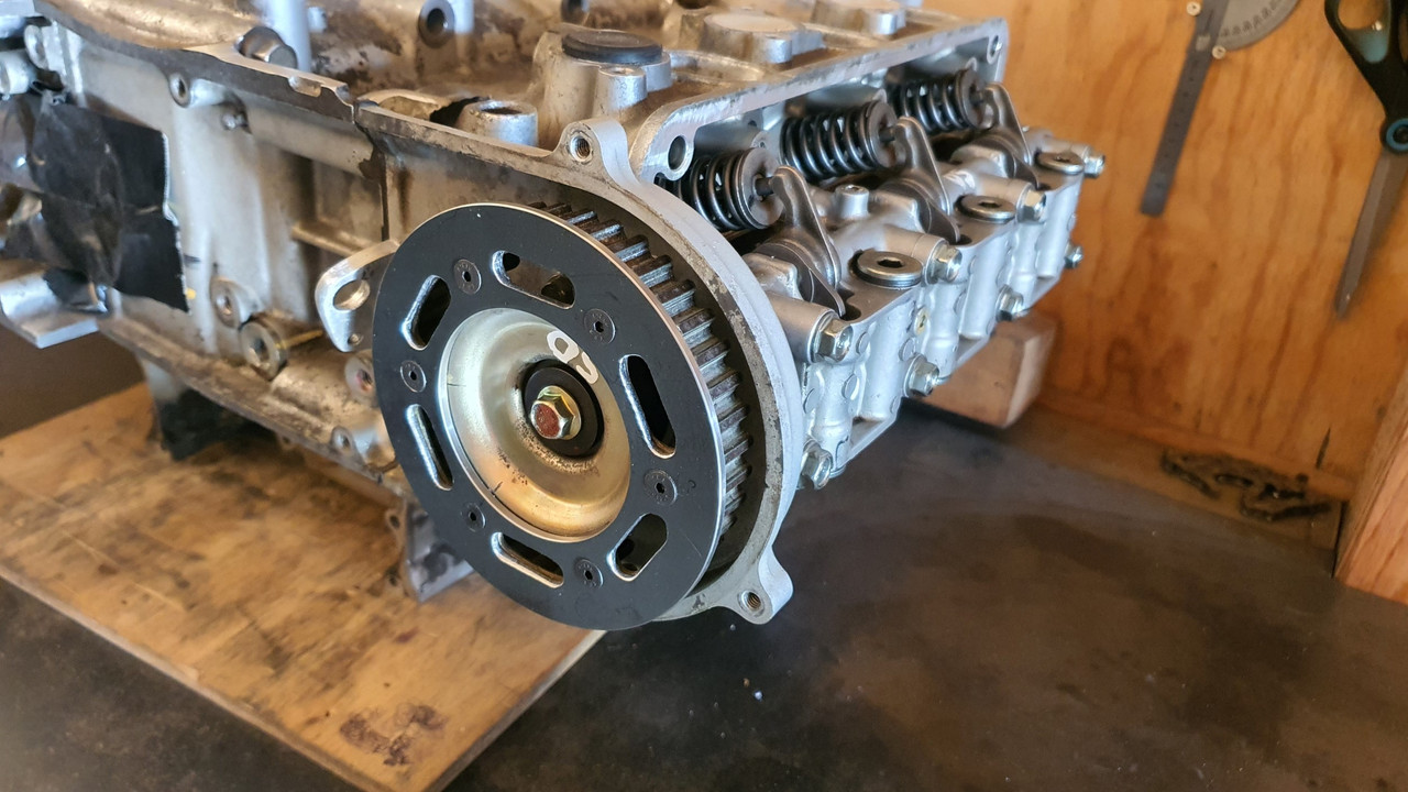
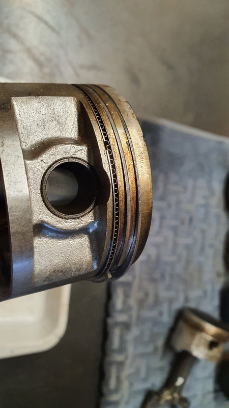
I then bolted the clean, shiny pistons in place. First to go in were the ones for the RH case that the crank is bolted into.

Image

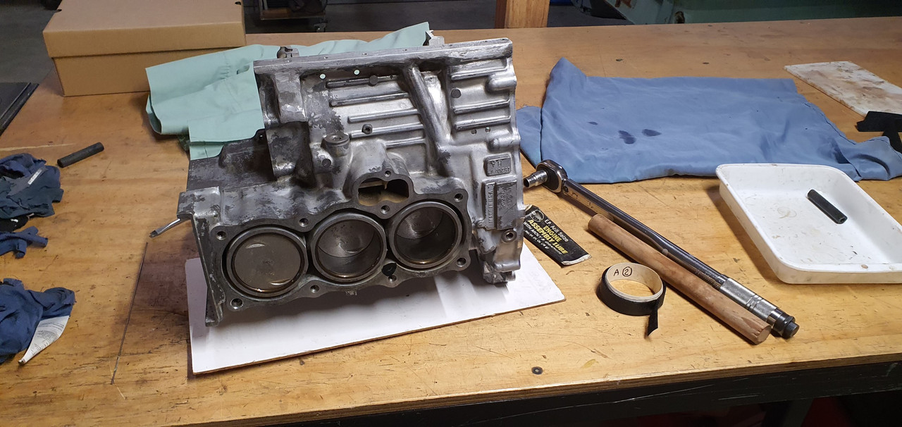
Then the left hand pistons get bolted in place...

Image

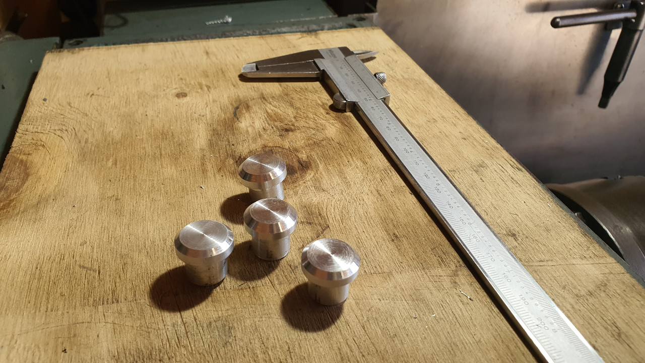
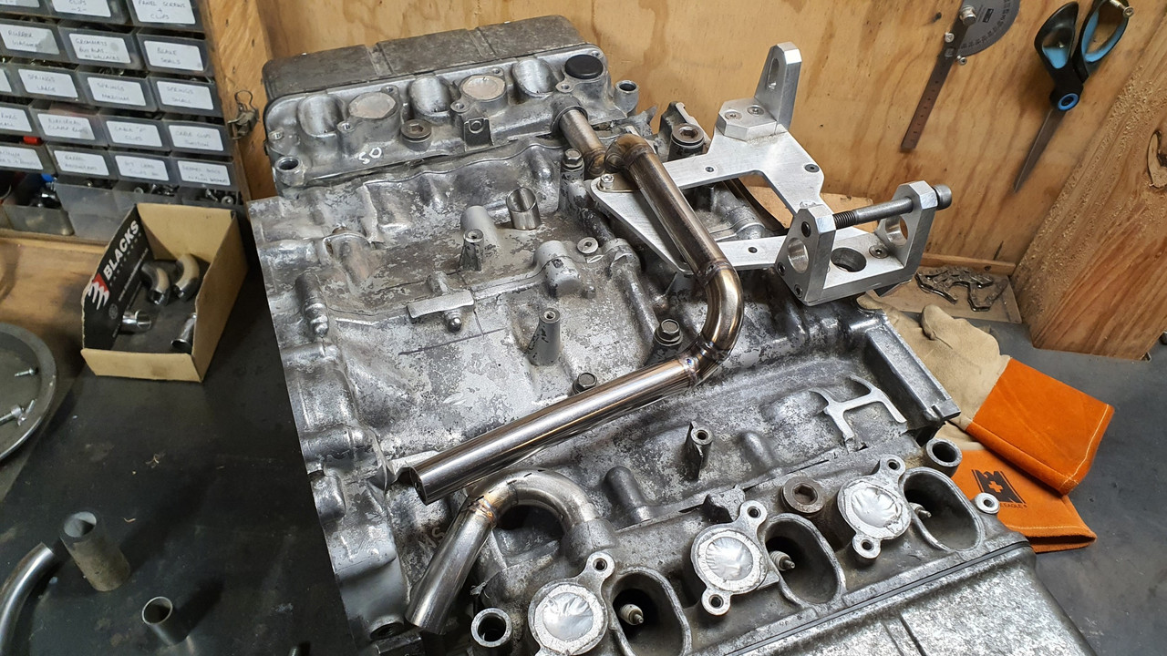
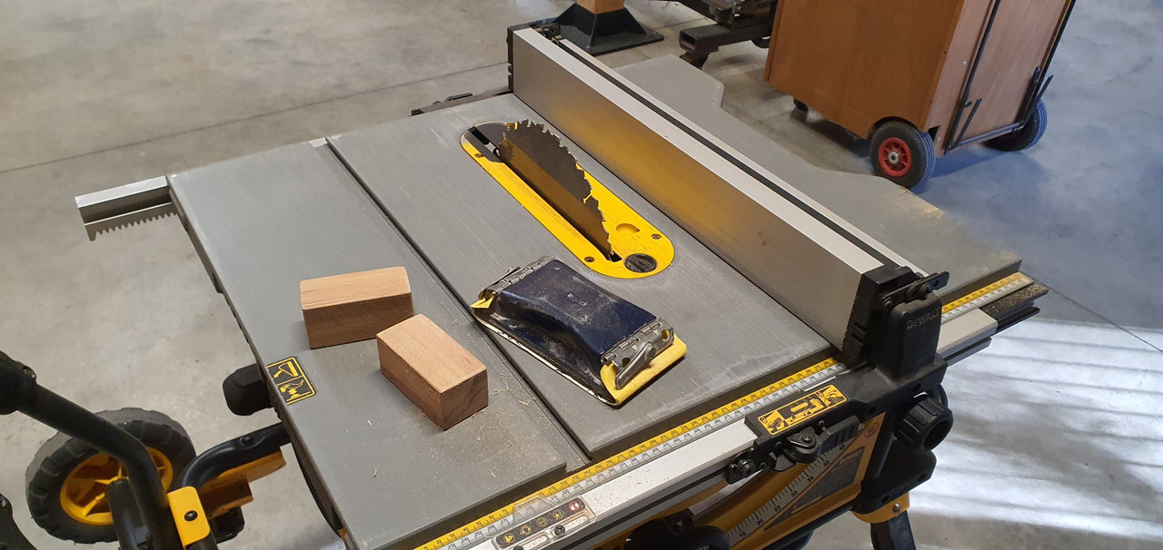
More tools. This time some woodwork. I searched in my wood supplies and found a nice lump of Eucalyptus. Firstly two support blocks made to measure according to sizes specified in the manuals. They are used to space the cases at certain stages.

Image

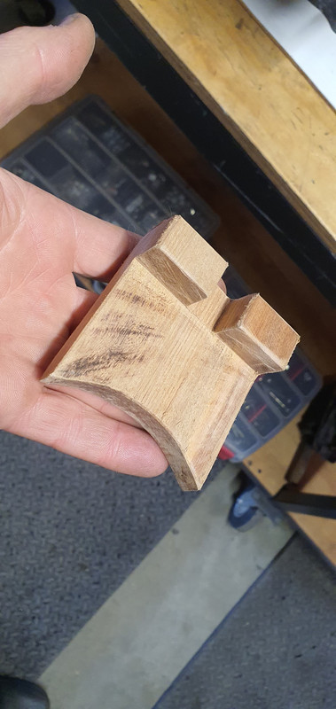
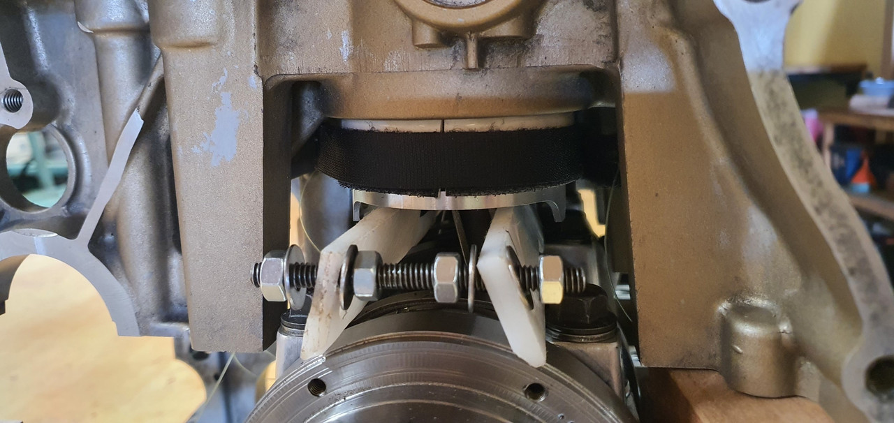
Then a trickier bit which is used to hold the upper most piston straight and in the right location.

Image

Image

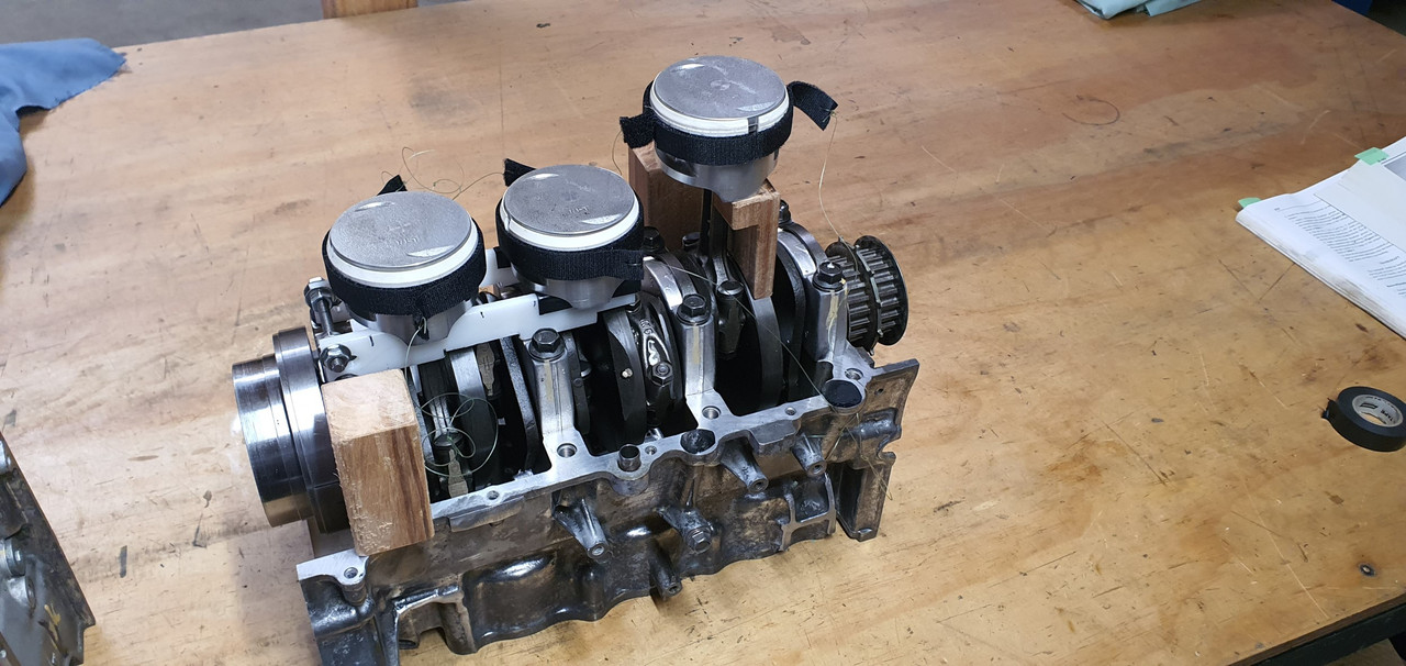
In that last pic you will note two white plastic supports for the two lower pistons. Honda sell these as part of the kit. Not cheap either. So I cut up a bit of plastic chopping board to suit. The velcro strips needed wire pulls as like the Honda items. I have no fine wire, or a piano to steal some from. But I have a fishing rod, now with a shorter line.

So it was all set up for the 'big lowering and clamshell manoeuvre'

Oil the bores, the piston crowns, carefully lower lh case. The top compressor slid down the piston, rings were inside the bore and the case sat on the upturned blocks. Remove the wooden piston support and then slide compressor down and remove by pulling on the fishing line loops.

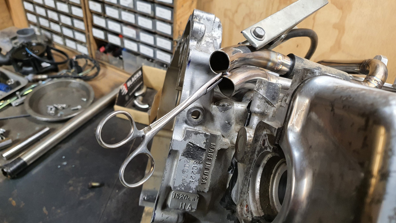
Please excuse the lack of photos. I was a combination of being both nervous and satisfied and not thinking camera. Not until the block was over the next two remaining pistons and rings were in place. Then I took some pics...

Image

Plastic chopping board supports removed..

Image

Final two compressors pulled out...

Image

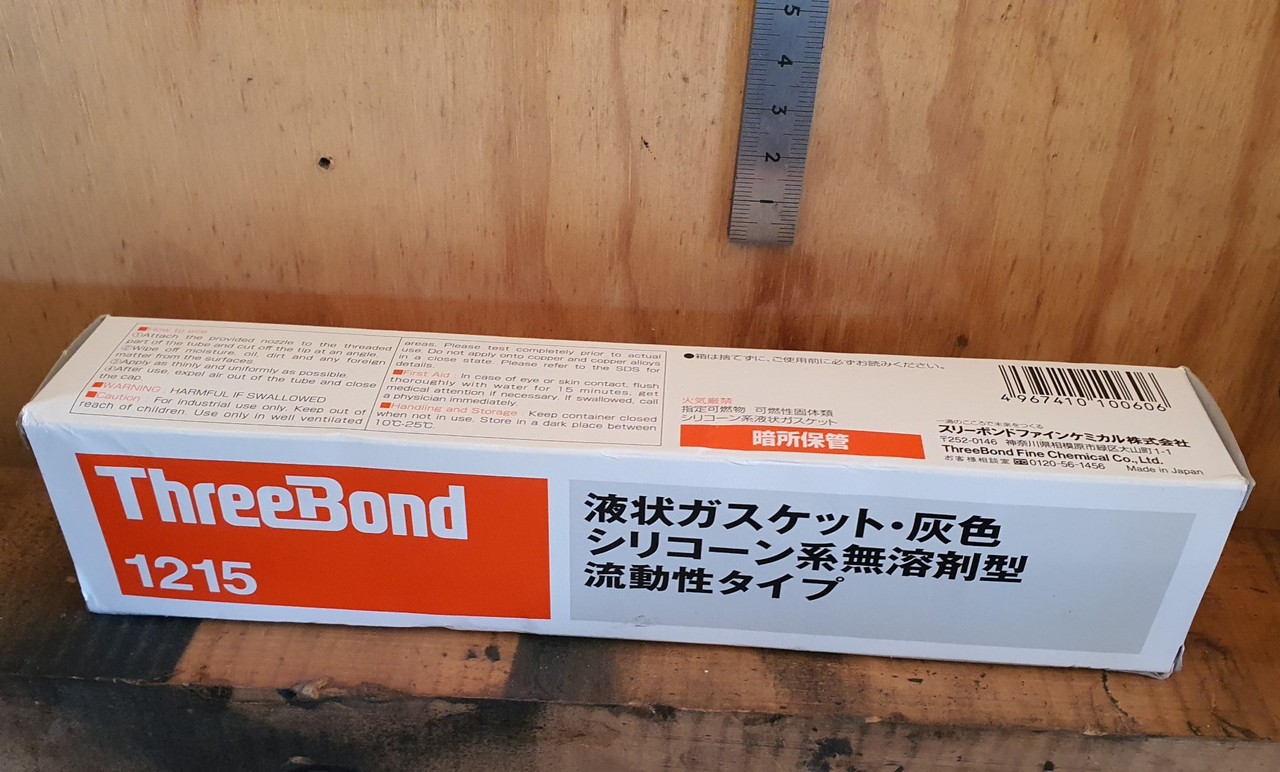
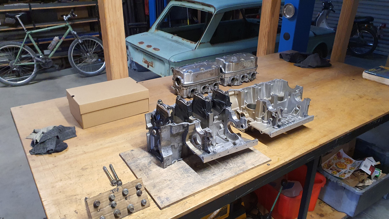
Case faces cleaned one more time, dowels reinserted, 2 new O rings installed, lower surface gets a thin spread of 3 Bond sealant. Case is lowered then all these cleaned and pre-organised bolts go in and get torqued down. Job done. Phew !!!

Image

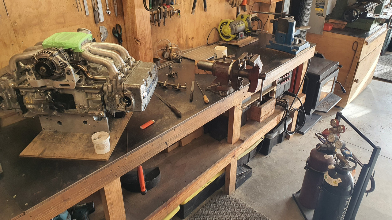
I had a cup of coffee (and cake!) and tidy up in preparation of the next stages. Its nice having a break from work and not having customers jobs cluttering up the space. Just the little spare Imp...

Image
Last edited by yoeddynz on Wed Aug 09, 2023 9:04 pm, edited 1 time in total.
911hillclimber
Nurse, I think I need some assistance
Posts: 18924
Joined: Mon Mar 10, 2008 6:26 pm
Location: West Midlands

Re: 1965 Hillman Imp soon with flat six from a Honda

Post by 911hillclimber »

Maga!!
Really interesting to see your solutions, 11/10 from me and many others i think.
I've rebuilt from the crank out 4 911 engines, and that closing stage is a bit taxing. I've done 2 Honda CB175 twins from the cranks out, and the miniaturization of everything adds to that same taxing feeling, but both pistons enter the cylinder block at the same time if you get everything square, not easy.

I too used 3 bond and never saw a leak on the Hondas. :cheers:
Looking for more details on the thrust bearing you have added.

Wife will be back soon, so press on! :wink:
73T 911 Coupe, road/hillclimber 3.2L
Lola t 492 / 3.2 hillclimb racer
Boxster 987 Gen II 2.9
Post Reply