

1965 Hillman Imp soon with flat six from a Honda
Moderator: Bootsy
Re: 1965 Hillman Imp soon with flat six from a Honda
Cheers. No more big car projects after this (he says now..) and anyway I have many ideas for future modifications that'll keep me busy enough just on this.
-
911hillclimber
- Nurse, I think I need some assistance
- Posts: 18924
- Joined: Mon Mar 10, 2008 6:26 pm
- Location: West Midlands
Re: 1965 Hillman Imp soon with flat six from a Honda
Good to read!
We used to have scrapyards like the one you raided above, but Heath n Safety shut the lot down.
Nothing better than a good scrap yard search.
We used to have scrapyards like the one you raided above, but Heath n Safety shut the lot down.
Nothing better than a good scrap yard search.
73T 911 Coupe, road/hillclimber 3.2L
Lola t 492 / 3.2 hillclimb racer
Boxster 987 Gen II 2.9
Lola t 492 / 3.2 hillclimb racer
Boxster 987 Gen II 2.9

Re: 1965 Hillman Imp soon with flat six from a Honda
That motor sounds a blast - a worthy successor to the Climax
maverick
noun
1. an unorthodox or independent-minded person.
2. an unbranded calf or yearling.
Origin mid 19th century: from the name of Samuel A. Maverick (1803–70), a Texas rancher who did not brand his cattle.
noun
1. an unorthodox or independent-minded person.
2. an unbranded calf or yearling.
Origin mid 19th century: from the name of Samuel A. Maverick (1803–70), a Texas rancher who did not brand his cattle.
Re: 1965 Hillman Imp soon with flat six from a Honda
Thanks fellas. Yes I love a good romantic day out at a scrap yard with the lady 
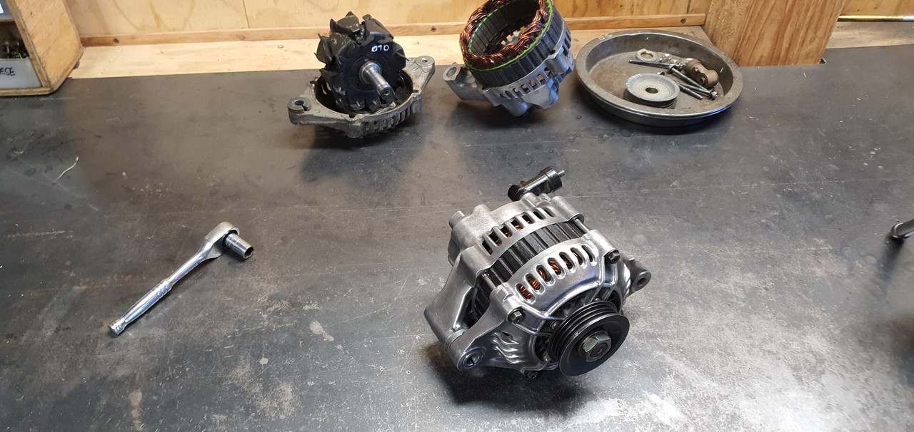
Ha. So pretty much the day after I had cleaned up that old alternator up and got it running on the engine the second hand replacement for my original unit turned up in the post.
It came with a 3 month warranty so I'd better check it works before stripping the engine of its ecu etc.
Started to fit it and oh..
Poos. It wont fit. So I took it apart, along with the original..
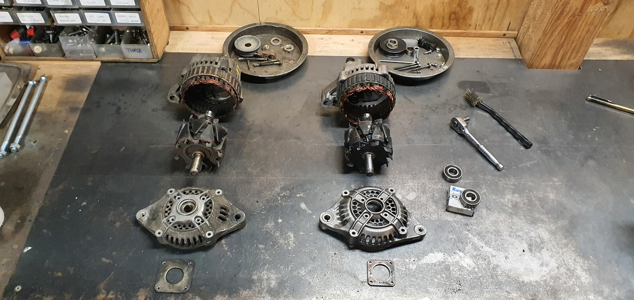
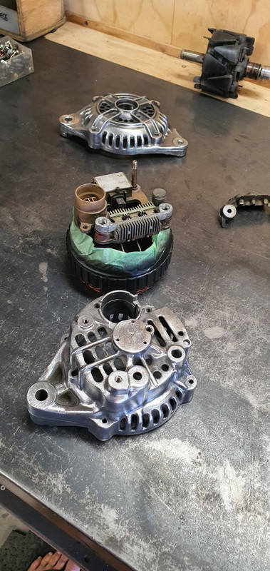
Discovered its just the front housing that's different and I can swap them across..
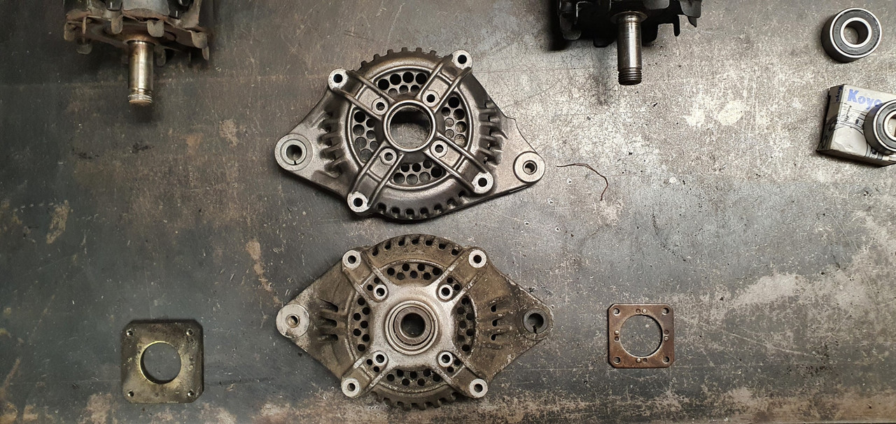
So while its apart it would be rude not to clean all the parts up and polish it all (tempting fate just a bit...)
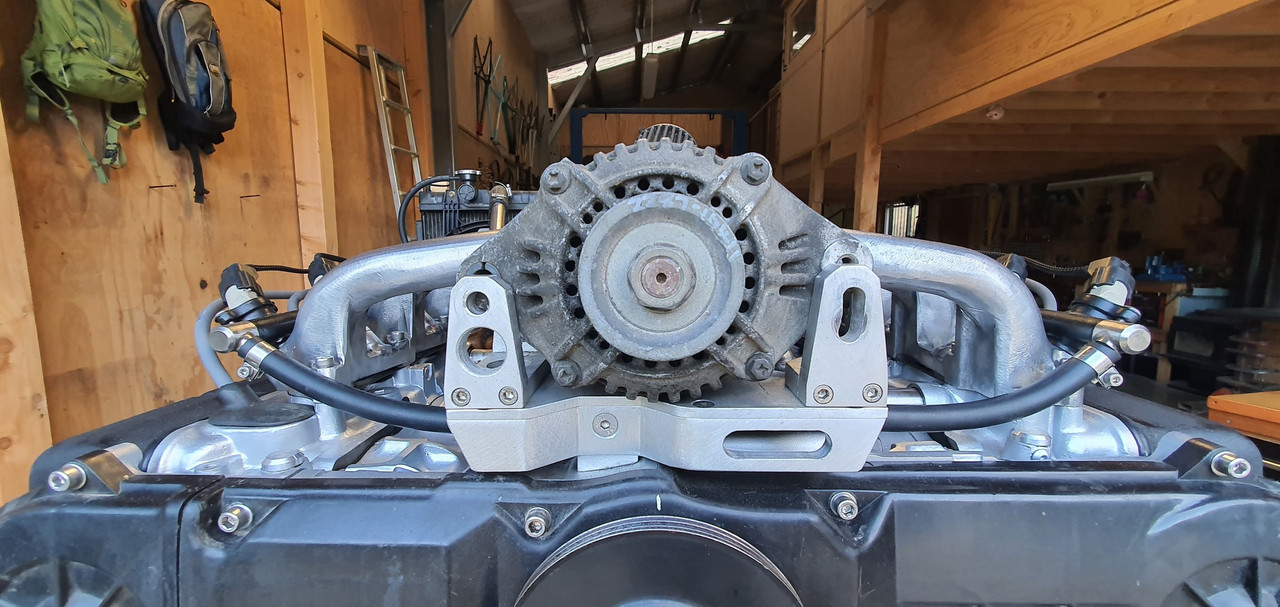
Fitted to the engine and started it up. Yay - it works and it looks great, which is really quite important given its right there, in the middle on display.
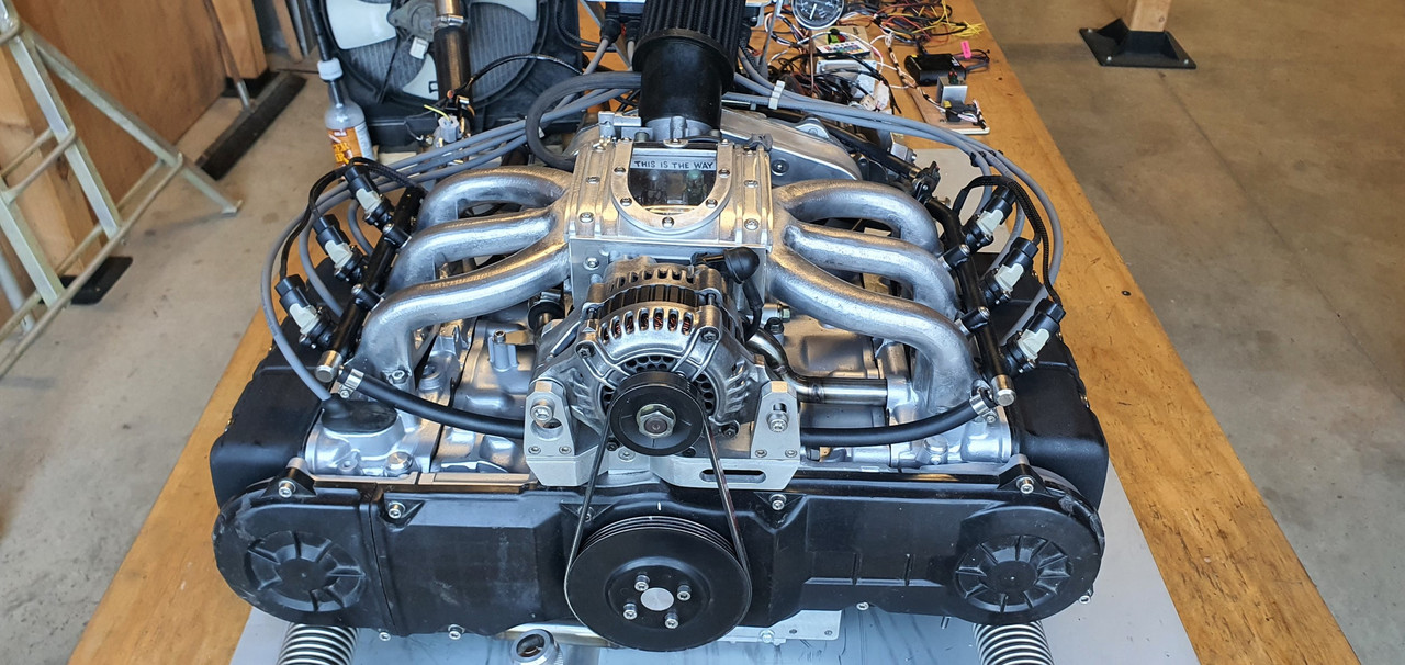
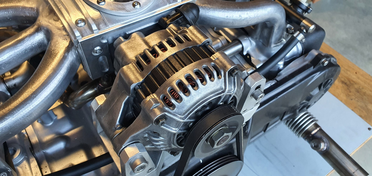
I'll keep the other one in storage just in case I need it one day.
Now I could strip the engine back down, removing all the cooling, wiring and fuel lines that I had installed just for bench testing. Then I removed the transmission and put the engine back onto the engine stand 2000, stashing it away because its gearbox tinkering time.
This Leone transmission has a few little issues that need sorting out in order for it to run in reverse rotation and not potentially turn itself into an expensive insinkerator or coffee grinder. I could probably get away without doing these modifications because the box is overbuilt for the application but I wanted peace of mind.
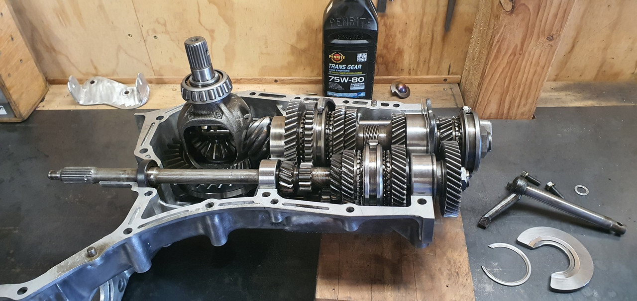
Remember I had acquired the two gearboxes, 1600 and 1800 items, before getting the engine. Ages ago, in fact 4 years ago I think!!! I had wanted to know if it was feasible to run these boxes in reverse. This pic I posted up way back then gives a good idea on what's going on inside...
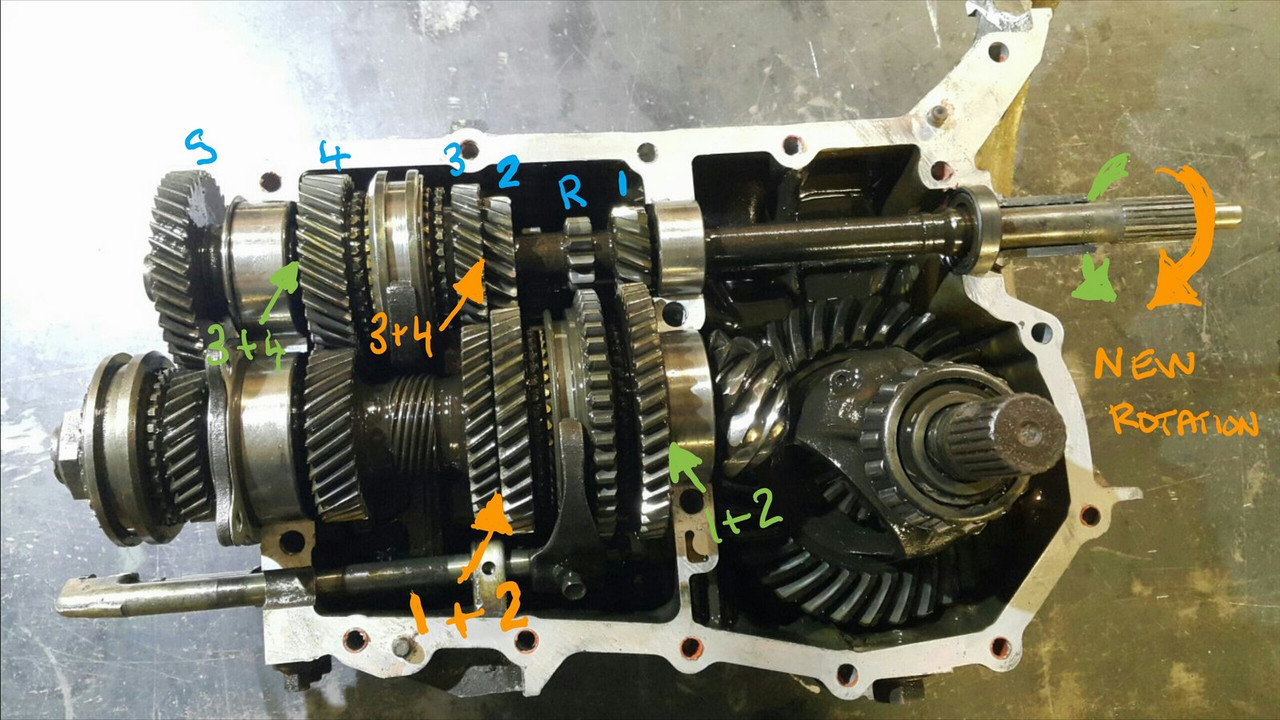
I had already worked out some of the issues back then and knew what I was up for. With more study I found a couple of other areas that need addressing. Here's another bit of wonderful scribbling I did this evening..
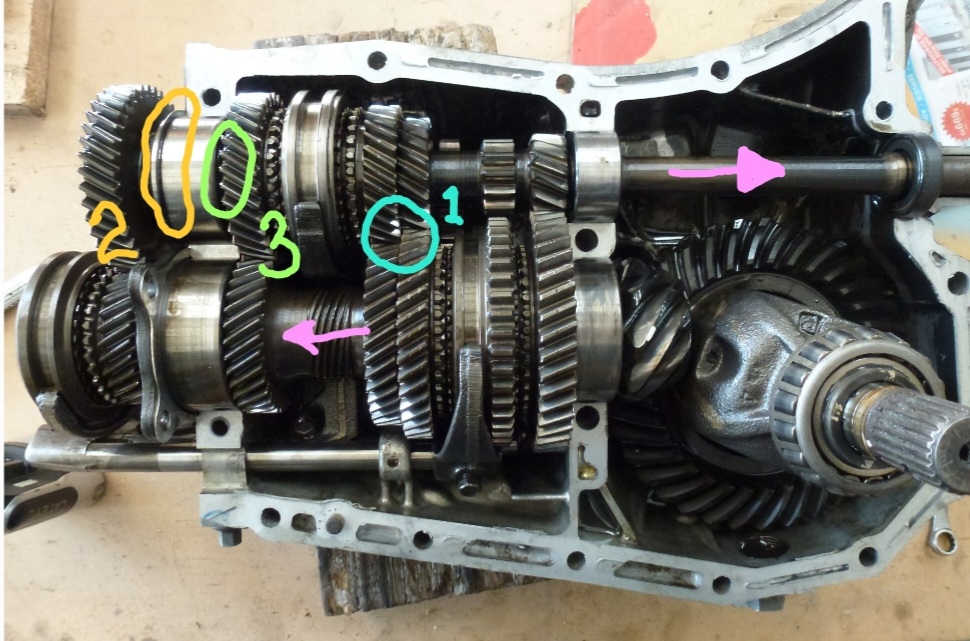
The pink arrows show the new axial forces that are being imparted onto the main (driver) shaft and pinion (driven) shaft. The circles are areas that I think needed attention to make sure it doesn't throw it toys from the cot.
1 : the blue circle. Under high torque loads this area could possibly create the sound of nashing teeth but with much messier consequences. The top left one being the third gear driver wants to move to the right and clip the teeth on the bottom right second gear. In normal rotation they would move apart. There's 1mm of clearance there which is probably enough tbh. But I wanted a bit more and had already worked out how I could get it with no other issues and just a bit of tool making. Which is fun.
2 : The yellow circle. This ring was no going to take thrust loading. It is a strong ring and has a deep groove but I wanted to make sure there was no way it could ever shift.
3 : the green circle. In this area there is a thrust bearing that also acts as a neat little oil pump and squeezes oil through the gear hubs/bushes. Under the new loading the thrust aspect is removed but I still wanted to it pump oil and it was going to be the wrong shape to do so in reverse rotation.
So I set to work and checked off each job. I made a bolt holder for ease of reassembly - several different sizes and lengths.
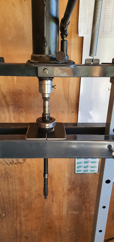
Once apart I started with the gear side clearance. First off I needed to split the mainshaft assembly down. 4 years ago I had out of interest tried using a puller on the spare 1600 box, which shares the same layout and design but with smaller parts in many cases. The puller didn't work. But this time round I have the rather handy workshop press I made. I just needed some extra tooling to do this job. Starting with some press plates...
Allowing me to carefully press the shaft out...
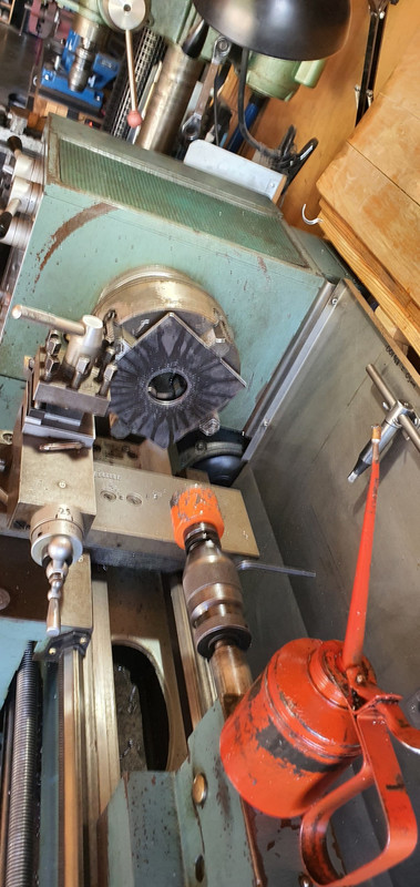
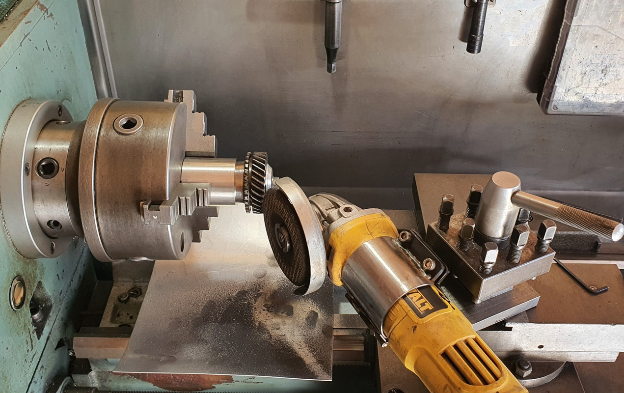
Because I'm not posh (or rich) enough to own a surface grinder I needed to make one. Yes its a bit basic but it will work. I made this...
Which allowed me to do this....
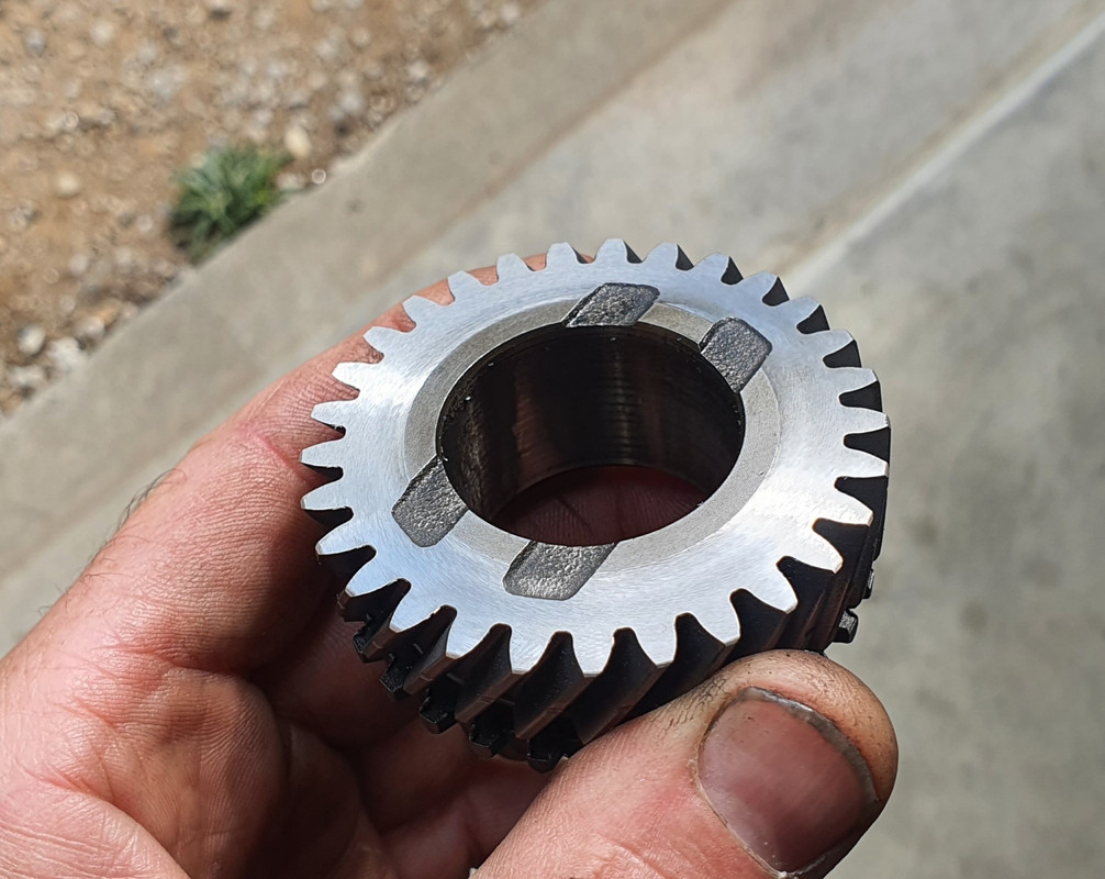
I ended up with this gear having the 0.5mm more clearance I wanted. Super happy with the result.
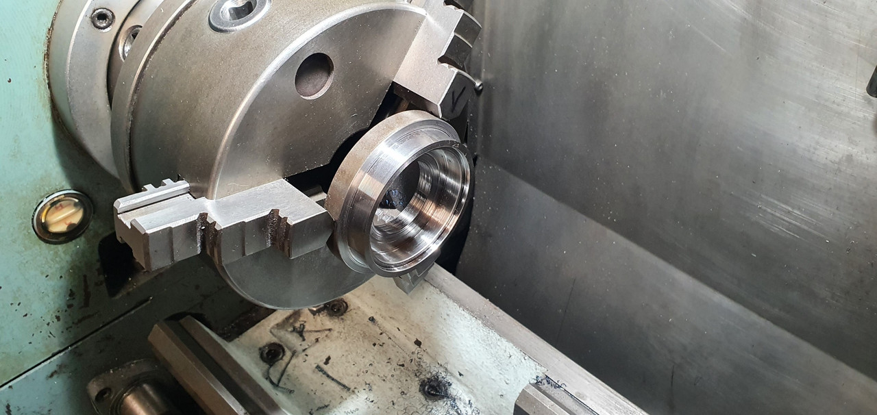
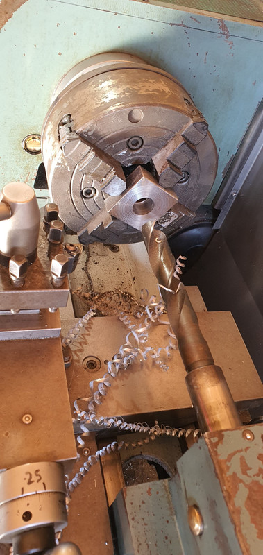
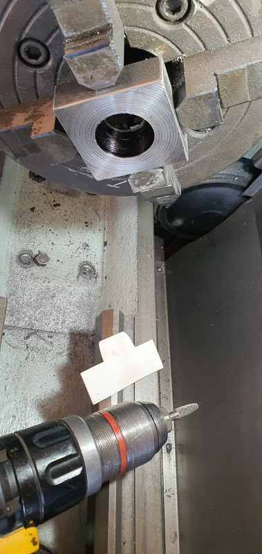
Now onto number 3 - the little oil pumpy thingee. I went to my friendly engineering workshop in town and got a big lump of 4140 steel. I drilled it out...
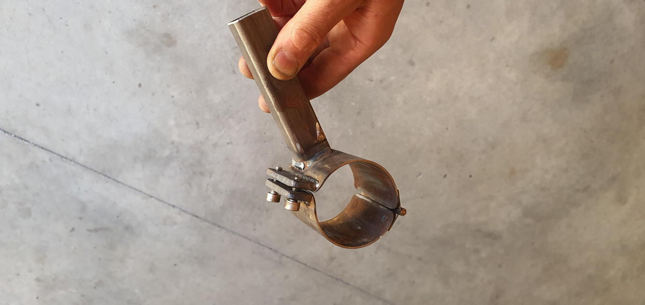
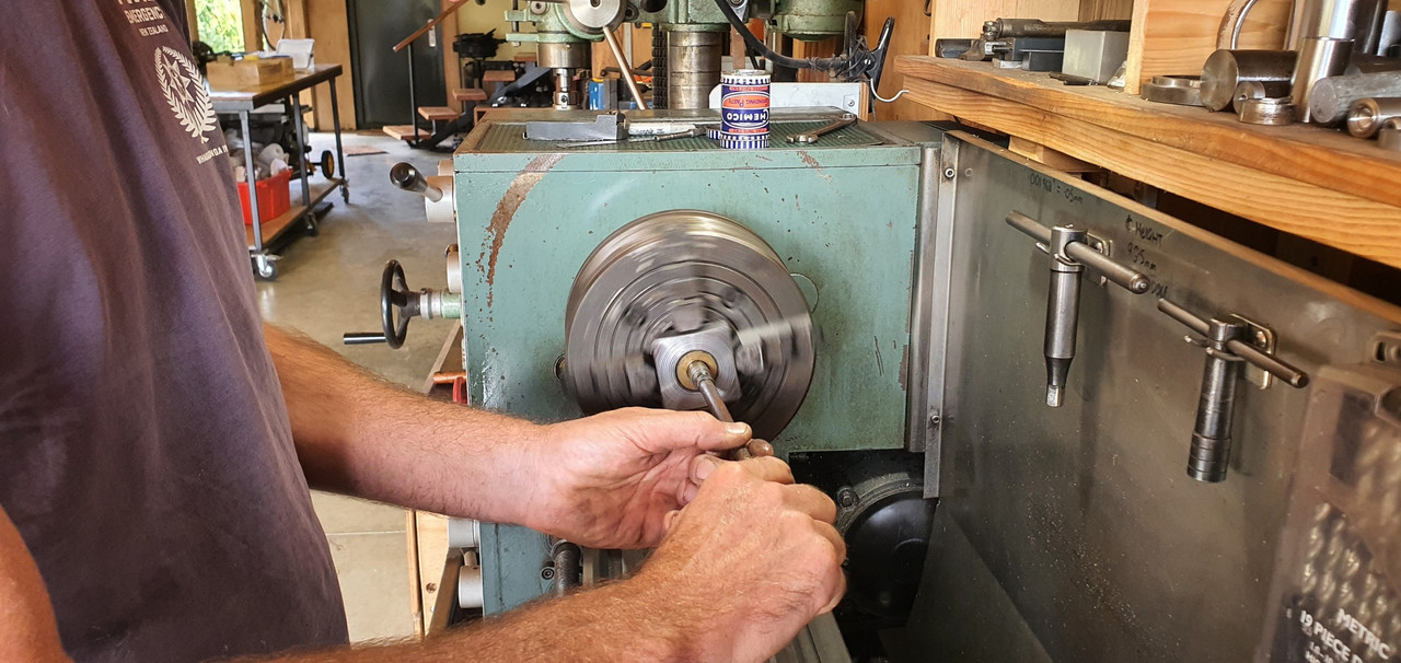
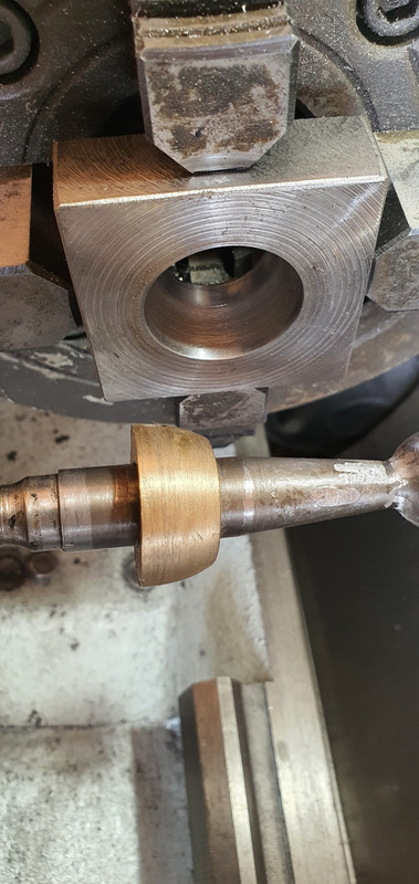
Machined out a ring which had to be an exact width. Just in case it needed finishing after the hardening process I made an abor to take it..
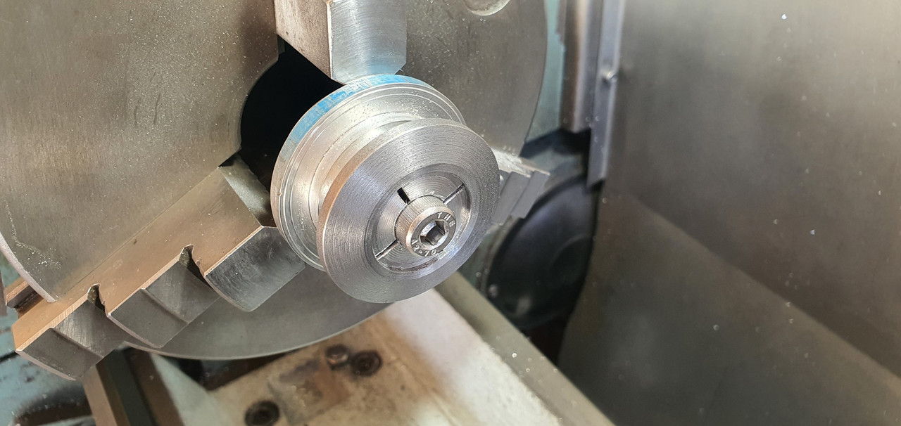
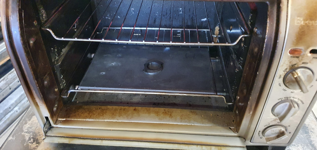
I carefully machined it to the right profile, cut the sides down and filed the shapes in, just like the original but in reverse. Happy it was going to work I heat treated it. I have not done any heat treating for over 25 years since I spent a fair bit of time in the blacksmith department while doing my apprenticeship. But it wasn't a super loaded critical component and just had to have a durable hard surface. I didn't take any photos. Hannah was there helping as I carefully heated it up with the oxycet to the austenitic stage and agitated it in some lovely rice bran oil (because I can be posh sometimes) then slapped it in the oven to temper it...
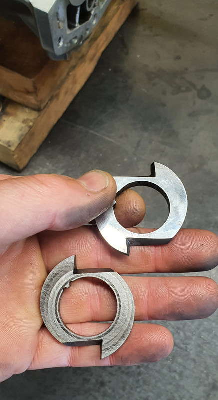
Following morning I polished it. It came up sweet and the old file test showed it to be as hard as the oem item.
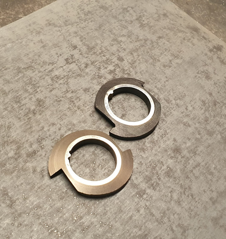
You can see the reversed design here...
Here's a little vid I took showing it in action...
https://www.youtube.com/watch?v=-3I1Sm1Qt8o
While stripping the mainshaft down I was also pleasantly surprised to discover that this 1800 box has needle bearings in all of the gear hubs unlike the 1600 box which uses bushes on the mainshaft. So oil starvation would not have been as much of an issue but I'm still really happy I did this modification.
Last issue to sort was number two - that ring on the bearing. It would hold fine I'm sure but if could make it bulletproof then why not - it's just a bit of extra machining. I started with another lump of high tensile steel and machined out a ring to suit...
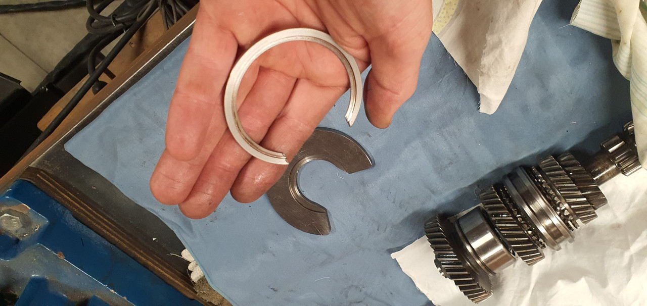
This fits over the other ring and then the main thrust plate that sits over the bearing was machined out to suit my reinforcement ring. Its all held in place by the end housing which I have yet to fit.
All the potential issues covered I set to cleaning out the casing and then started reassembly. In doing so I discovered that the original axle seals are sided on these boxes. They have those helical lines on the lip surfaces which aid in pulling/pumping oil back into the oil side of the lip ( the lip does not actually touch the steel when the axle is moving and in fact runs on a tiny bed of oil) which I had not realised before I'd bought plain lip seals from an engineering supplies. This pumping capacity is shown to be twice as high in helixed seals. Subaru fit left and right handed items. But I'm running mine in reverse. Luckily the originals were in excellent condition anyway so I machined up a stepped tool, popped them out and swapped them to the other side.
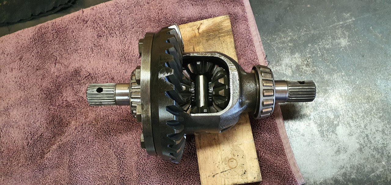
The diff axle seal surfaces came up good after a clean. Cute little diff..
I'm now about ready to put some 3 bond gloop on the case half and drop the other side in place. Its looking all very nice, clean and shiny in there...
Ha. So pretty much the day after I had cleaned up that old alternator up and got it running on the engine the second hand replacement for my original unit turned up in the post.
It came with a 3 month warranty so I'd better check it works before stripping the engine of its ecu etc.
Started to fit it and oh..
Poos. It wont fit. So I took it apart, along with the original..
Discovered its just the front housing that's different and I can swap them across..
So while its apart it would be rude not to clean all the parts up and polish it all (tempting fate just a bit...)
Fitted to the engine and started it up. Yay - it works and it looks great, which is really quite important given its right there, in the middle on display.
I'll keep the other one in storage just in case I need it one day.
Now I could strip the engine back down, removing all the cooling, wiring and fuel lines that I had installed just for bench testing. Then I removed the transmission and put the engine back onto the engine stand 2000, stashing it away because its gearbox tinkering time.
This Leone transmission has a few little issues that need sorting out in order for it to run in reverse rotation and not potentially turn itself into an expensive insinkerator or coffee grinder. I could probably get away without doing these modifications because the box is overbuilt for the application but I wanted peace of mind.
Remember I had acquired the two gearboxes, 1600 and 1800 items, before getting the engine. Ages ago, in fact 4 years ago I think!!! I had wanted to know if it was feasible to run these boxes in reverse. This pic I posted up way back then gives a good idea on what's going on inside...
I had already worked out some of the issues back then and knew what I was up for. With more study I found a couple of other areas that need addressing. Here's another bit of wonderful scribbling I did this evening..
The pink arrows show the new axial forces that are being imparted onto the main (driver) shaft and pinion (driven) shaft. The circles are areas that I think needed attention to make sure it doesn't throw it toys from the cot.
1 : the blue circle. Under high torque loads this area could possibly create the sound of nashing teeth but with much messier consequences. The top left one being the third gear driver wants to move to the right and clip the teeth on the bottom right second gear. In normal rotation they would move apart. There's 1mm of clearance there which is probably enough tbh. But I wanted a bit more and had already worked out how I could get it with no other issues and just a bit of tool making. Which is fun.
2 : The yellow circle. This ring was no going to take thrust loading. It is a strong ring and has a deep groove but I wanted to make sure there was no way it could ever shift.
3 : the green circle. In this area there is a thrust bearing that also acts as a neat little oil pump and squeezes oil through the gear hubs/bushes. Under the new loading the thrust aspect is removed but I still wanted to it pump oil and it was going to be the wrong shape to do so in reverse rotation.
So I set to work and checked off each job. I made a bolt holder for ease of reassembly - several different sizes and lengths.
Once apart I started with the gear side clearance. First off I needed to split the mainshaft assembly down. 4 years ago I had out of interest tried using a puller on the spare 1600 box, which shares the same layout and design but with smaller parts in many cases. The puller didn't work. But this time round I have the rather handy workshop press I made. I just needed some extra tooling to do this job. Starting with some press plates...
Allowing me to carefully press the shaft out...
Because I'm not posh (or rich) enough to own a surface grinder I needed to make one. Yes its a bit basic but it will work. I made this...
Which allowed me to do this....
I ended up with this gear having the 0.5mm more clearance I wanted. Super happy with the result.
Now onto number 3 - the little oil pumpy thingee. I went to my friendly engineering workshop in town and got a big lump of 4140 steel. I drilled it out...
Machined out a ring which had to be an exact width. Just in case it needed finishing after the hardening process I made an abor to take it..
I carefully machined it to the right profile, cut the sides down and filed the shapes in, just like the original but in reverse. Happy it was going to work I heat treated it. I have not done any heat treating for over 25 years since I spent a fair bit of time in the blacksmith department while doing my apprenticeship. But it wasn't a super loaded critical component and just had to have a durable hard surface. I didn't take any photos. Hannah was there helping as I carefully heated it up with the oxycet to the austenitic stage and agitated it in some lovely rice bran oil (because I can be posh sometimes) then slapped it in the oven to temper it...
Following morning I polished it. It came up sweet and the old file test showed it to be as hard as the oem item.
You can see the reversed design here...
Here's a little vid I took showing it in action...
https://www.youtube.com/watch?v=-3I1Sm1Qt8o
While stripping the mainshaft down I was also pleasantly surprised to discover that this 1800 box has needle bearings in all of the gear hubs unlike the 1600 box which uses bushes on the mainshaft. So oil starvation would not have been as much of an issue but I'm still really happy I did this modification.
Last issue to sort was number two - that ring on the bearing. It would hold fine I'm sure but if could make it bulletproof then why not - it's just a bit of extra machining. I started with another lump of high tensile steel and machined out a ring to suit...
This fits over the other ring and then the main thrust plate that sits over the bearing was machined out to suit my reinforcement ring. Its all held in place by the end housing which I have yet to fit.
All the potential issues covered I set to cleaning out the casing and then started reassembly. In doing so I discovered that the original axle seals are sided on these boxes. They have those helical lines on the lip surfaces which aid in pulling/pumping oil back into the oil side of the lip ( the lip does not actually touch the steel when the axle is moving and in fact runs on a tiny bed of oil) which I had not realised before I'd bought plain lip seals from an engineering supplies. This pumping capacity is shown to be twice as high in helixed seals. Subaru fit left and right handed items. But I'm running mine in reverse. Luckily the originals were in excellent condition anyway so I machined up a stepped tool, popped them out and swapped them to the other side.
The diff axle seal surfaces came up good after a clean. Cute little diff..
I'm now about ready to put some 3 bond gloop on the case half and drop the other side in place. Its looking all very nice, clean and shiny in there...
Last edited by yoeddynz on Wed Feb 21, 2024 7:36 pm, edited 1 time in total.
-
Ian Comerford
- I luv DDK!
- Posts: 773
- Joined: Fri Apr 01, 2005 8:51 am
- Location: Harston, Leics
Re: 1965 Hillman Imp soon with flat six from a Honda
Near genius! Thanks for sharing again, great to read this.
-
sladey
- Nurse, I think I need some assistance
- Posts: 8728
- Joined: Sat Apr 23, 2005 9:08 pm
- Location: Nottingham, UK
Re: 1965 Hillman Imp soon with flat six from a Honda
Brilliant stuff and fascinating reading
The simple things you see are all complicated
I look pretty young but I'm just backdated yeah
I look pretty young but I'm just backdated yeah
-
911hillclimber
- Nurse, I think I need some assistance
- Posts: 18924
- Joined: Mon Mar 10, 2008 6:26 pm
- Location: West Midlands
Re: 1965 Hillman Imp soon with flat six from a Honda
Indeed, and with a lathe you can tackle as good as anything! 
73T 911 Coupe, road/hillclimber 3.2L
Lola t 492 / 3.2 hillclimb racer
Boxster 987 Gen II 2.9
Lola t 492 / 3.2 hillclimb racer
Boxster 987 Gen II 2.9
Re: 1965 Hillman Imp soon with flat six from a Honda
Thanks fellas. Glad you're enjoying the read.
Re: 1965 Hillman Imp soon with flat six from a Honda
I glooped the two halves together, bolted them up, bolted the tailhousing on and let it set. Following morning it was bolted onto the engine, unsurprisingly a bit heftier with all the gubbins placed back within the box. Its about 9kg heavier than the standard imp box.
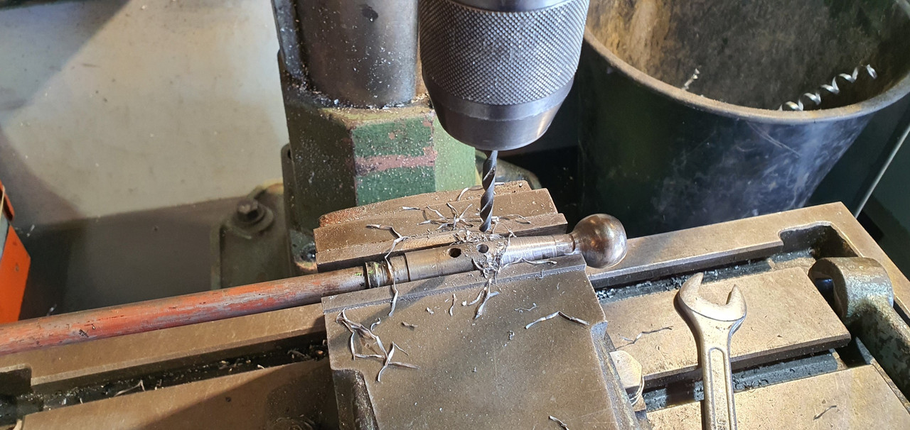
I then started to fit the first part of the gearshift linkage. The first of those snazzy universal joints, handily available in a diameter to suit the shifter shaft on the Subaru box. I just needed to add a small locating hole for the grub screw...
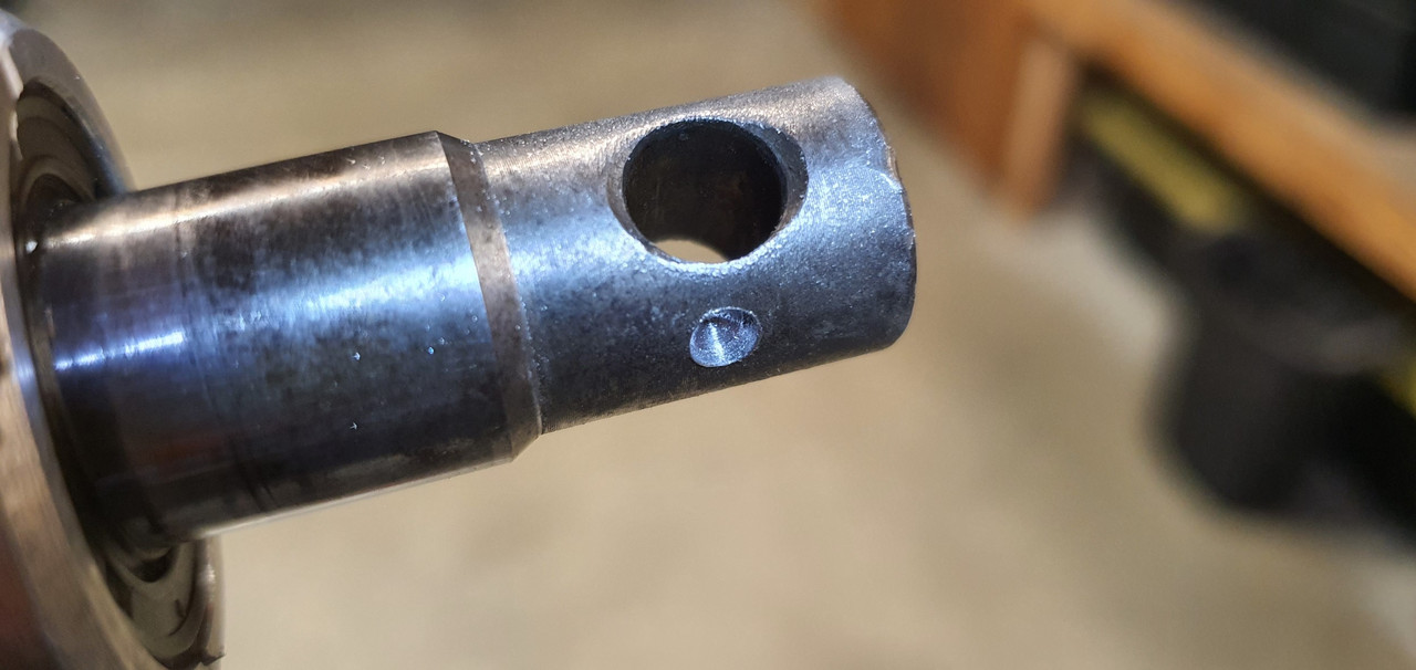
Universal in place..
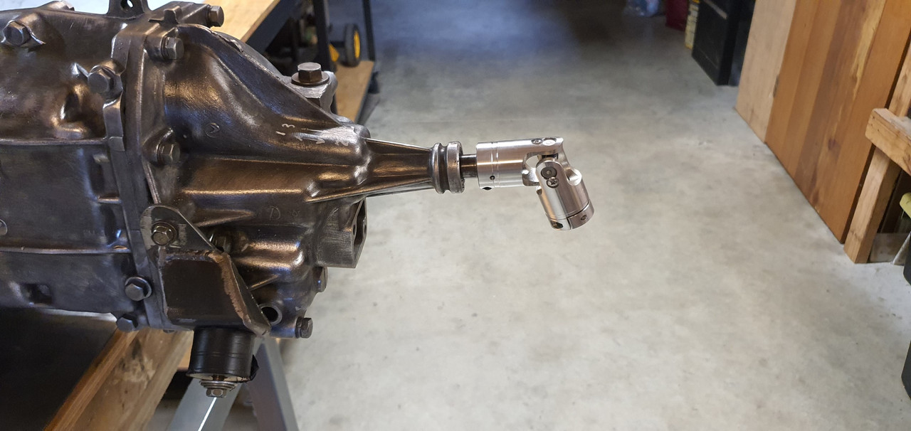
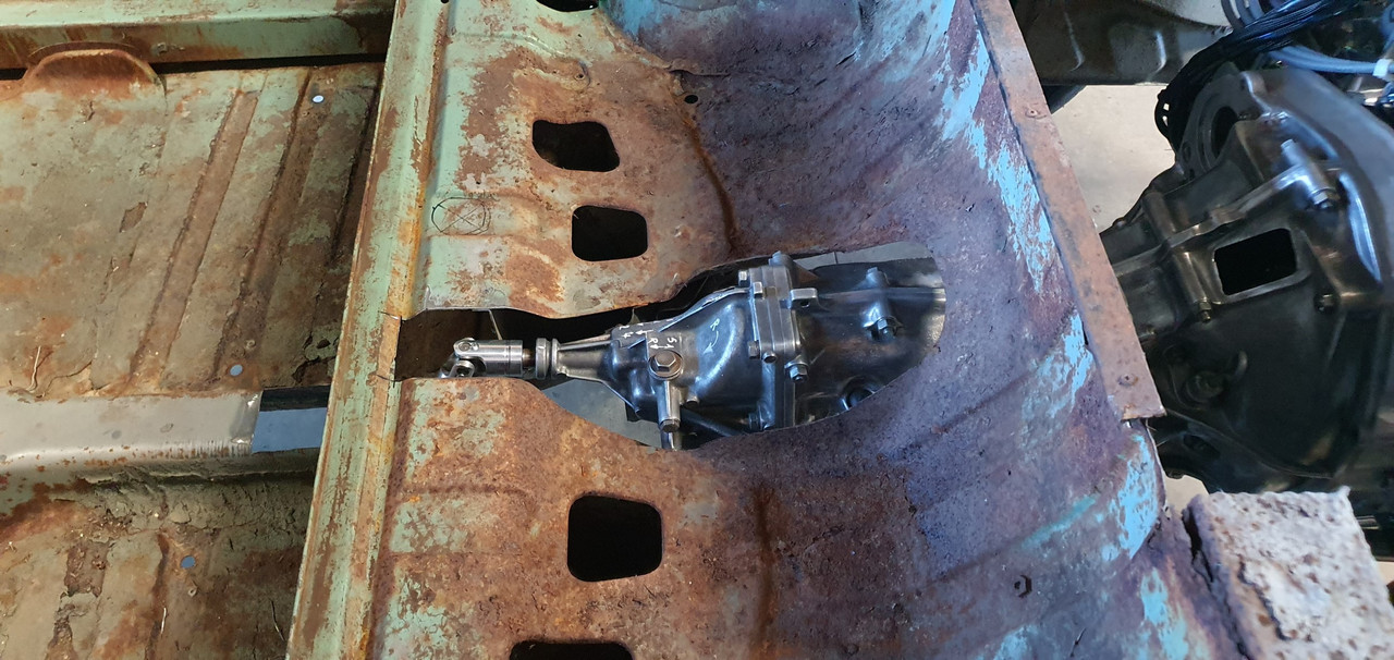
Engine and box were then bolted back into the car. This bit is so quick and easy when using the 'engine stand 2000'. It takes about 10 mins and I'm getting quicker. It'll be slower when there's shift linkage to undo and driveshafts to slip out of the way. But at least the main heavy awkward part is actually easy.
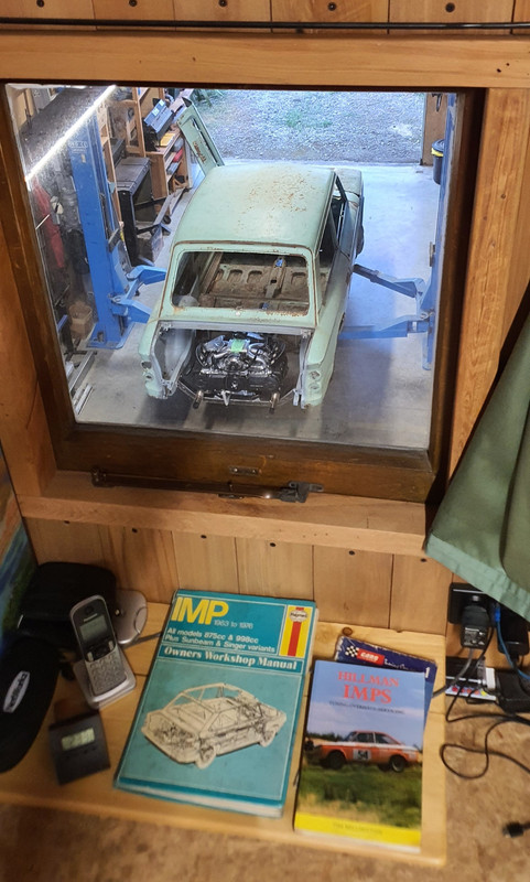
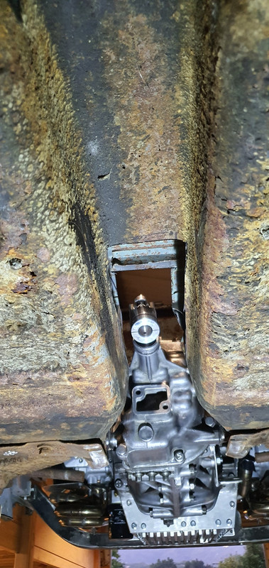
That lot in place I took some pics. Its neat to be able to look out from the one of the lounge room windows down onto the workshop floor and see this...
With that lot in place I was able to suss out the angles I could get away with, as shallow as possible and allowing for the handbrake mechanism.
I had this old imp gearstick assembly that a fellow Imp friend kindly posted over to me. Some previous owner of the car he got it from liked painting things. Everything. Multiple times...
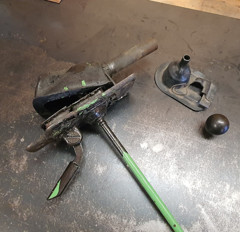
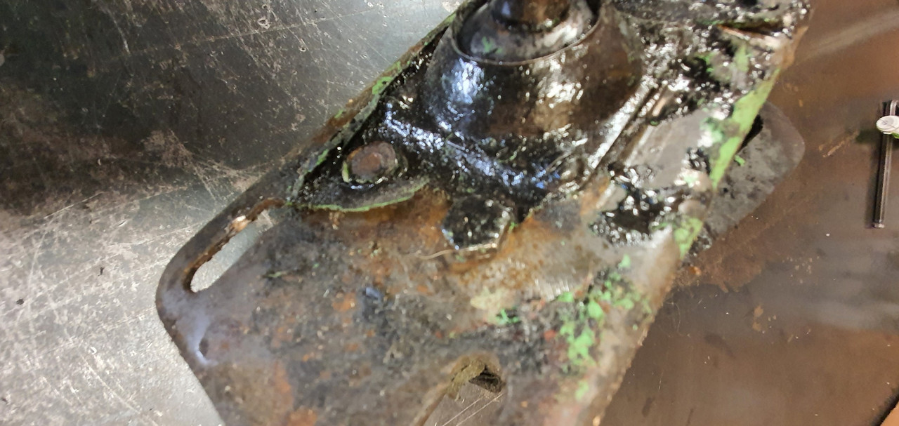
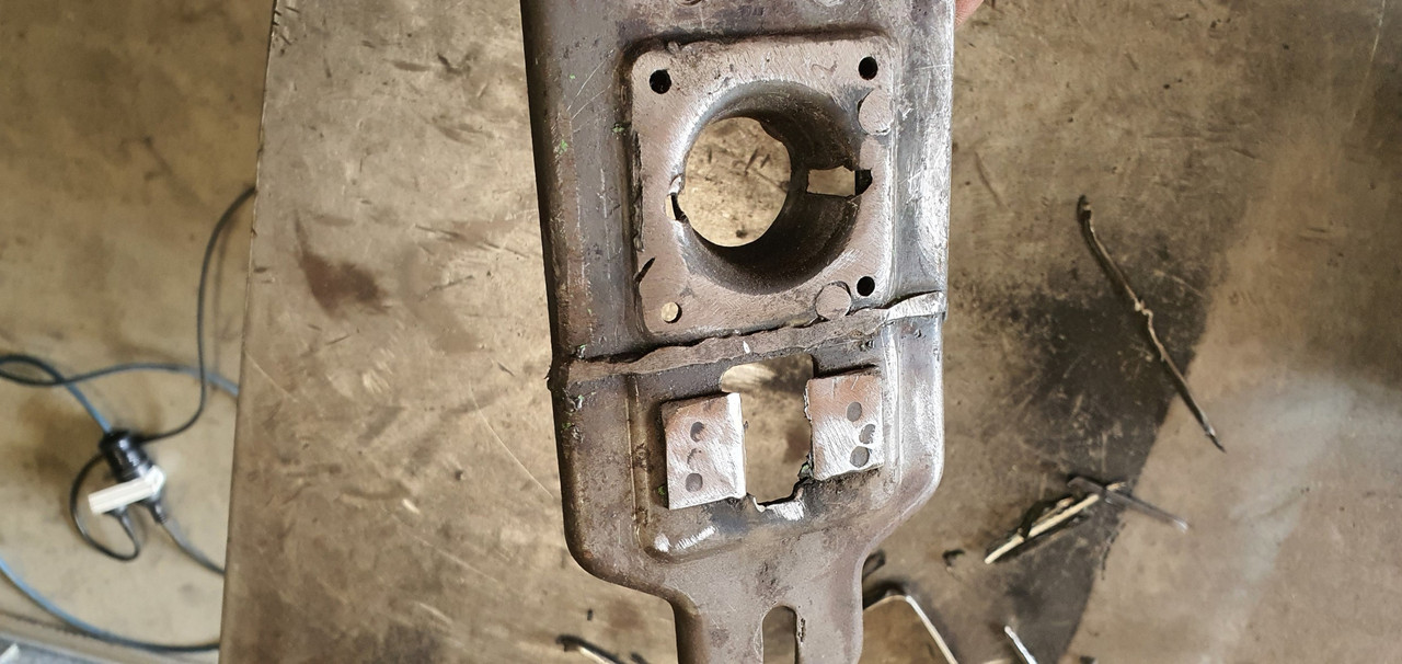
I scrapped all the layers off, took it apart and cleaned off the dirty old grease. Discovered it had been cobbled together from two old shifter bases. It was originally a very early Imp unit when the very first cars had an automatic choke, which often proved problematic. Hillman then changed the cars over to a manual choke with a nifty little lever in front of the shifter. This mount had been added to the early base. Which means they must have chopped up a later baseplate to get the choke mount. Why they didn't just fit the entire newer base plate I don't know. But what I had in front of me was a frankenstein of base plates with barry spec welding and fixes, but also including a not too badly made bronze bush on the lever where there is normally a (wornout) plastic bush.
I had a couple of shift rods to choose from. I chose the least worn.
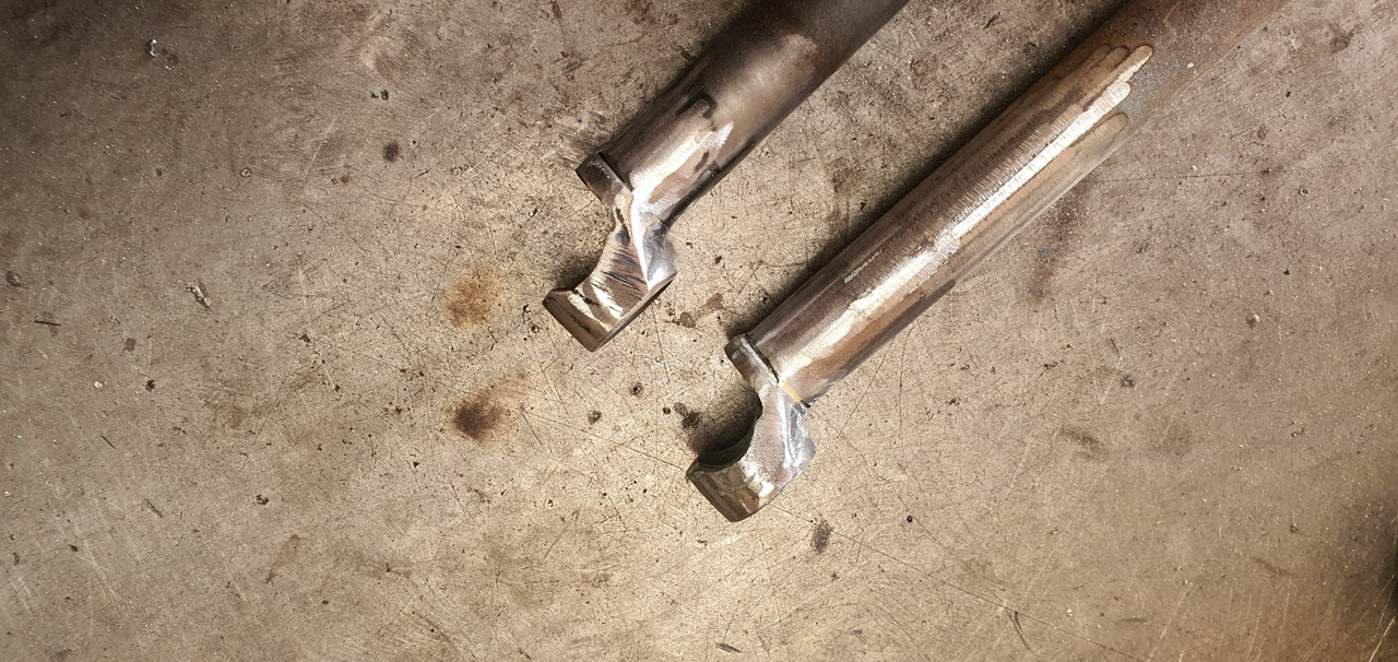
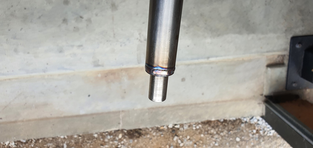
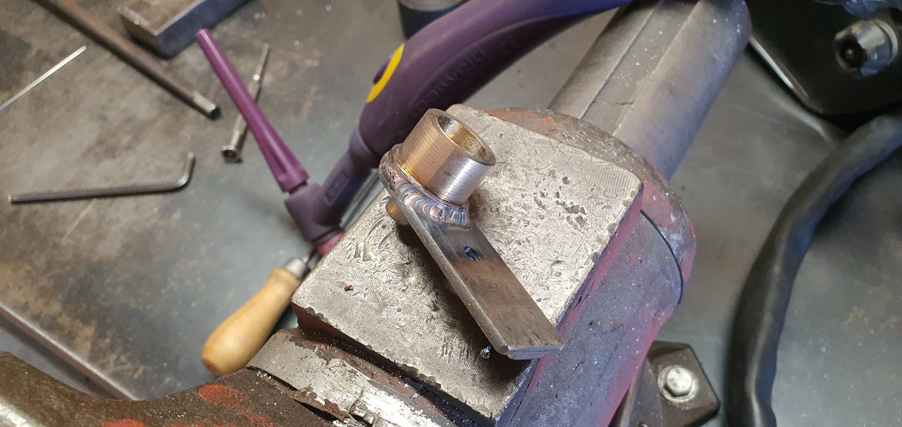
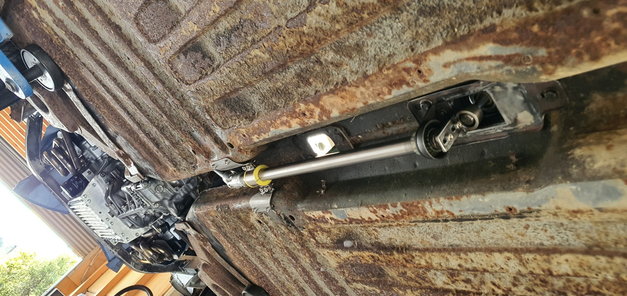
Moving back to the gearbox end I machined up some shaft ends from stainless bar to suit the universal joints. I had some stainless tube and welded the ends in place on the first shaft that runs from the gearbox universal down to the tunnel.
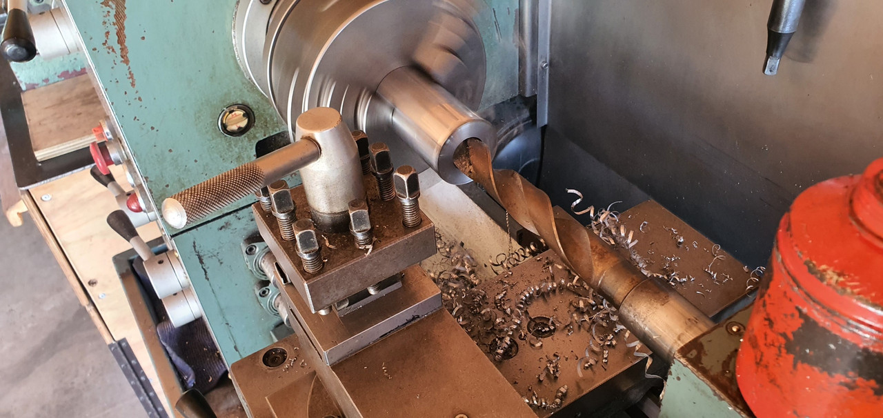
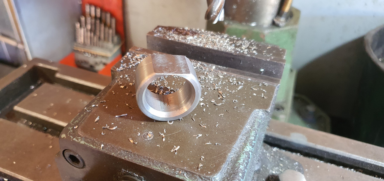
Now I needed a sturdy, slippery support to mount in place of the second universal joint. This will not only take back and forth movement on the shaft but also a bit of thrust loading created by the angle on the connecting shaft. I had already bought a lump of slippery hard engineering plastic with this application in mind when I had ordered the plastic for the flywheel thrust bearing a while back. It was bright yellow. Luckily not seen under the car as it would clash with the blue paint. I put a hole in it and machined the outside down.
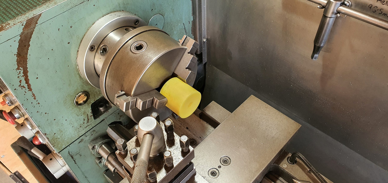
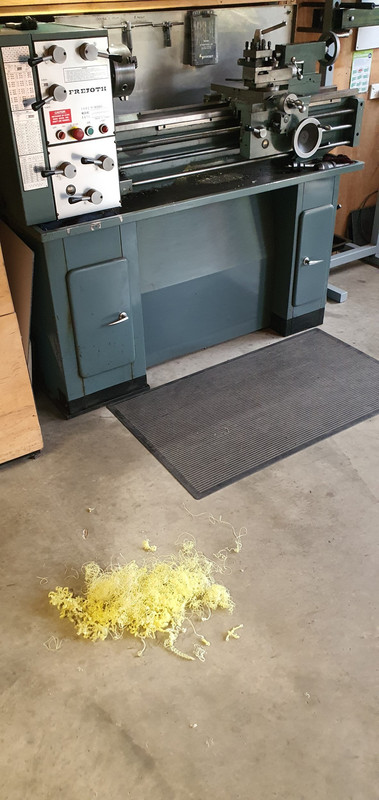
Which also created a pile of pretty swarf..
Then reamed it out to 1"
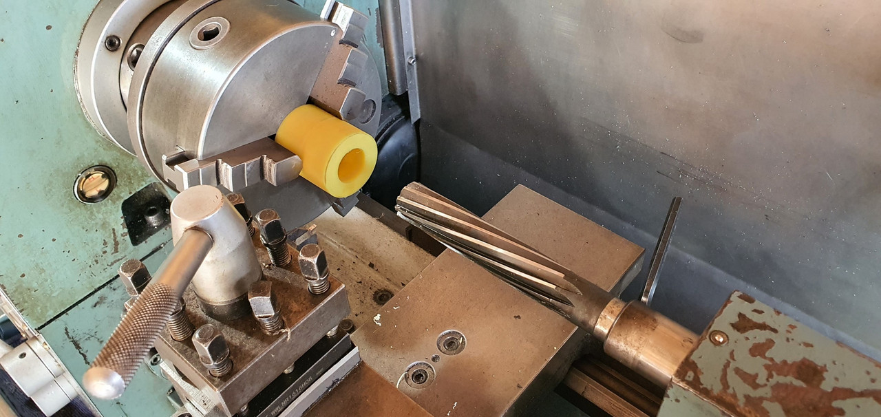
Still a bit tight so out with the adjustable reamers..
until it was just right...
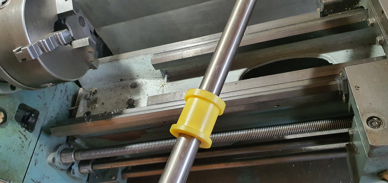
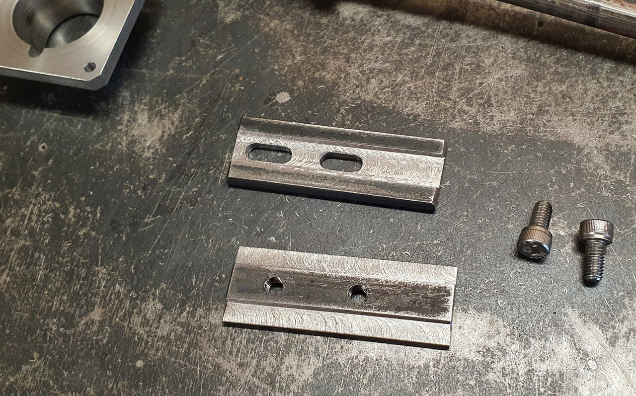
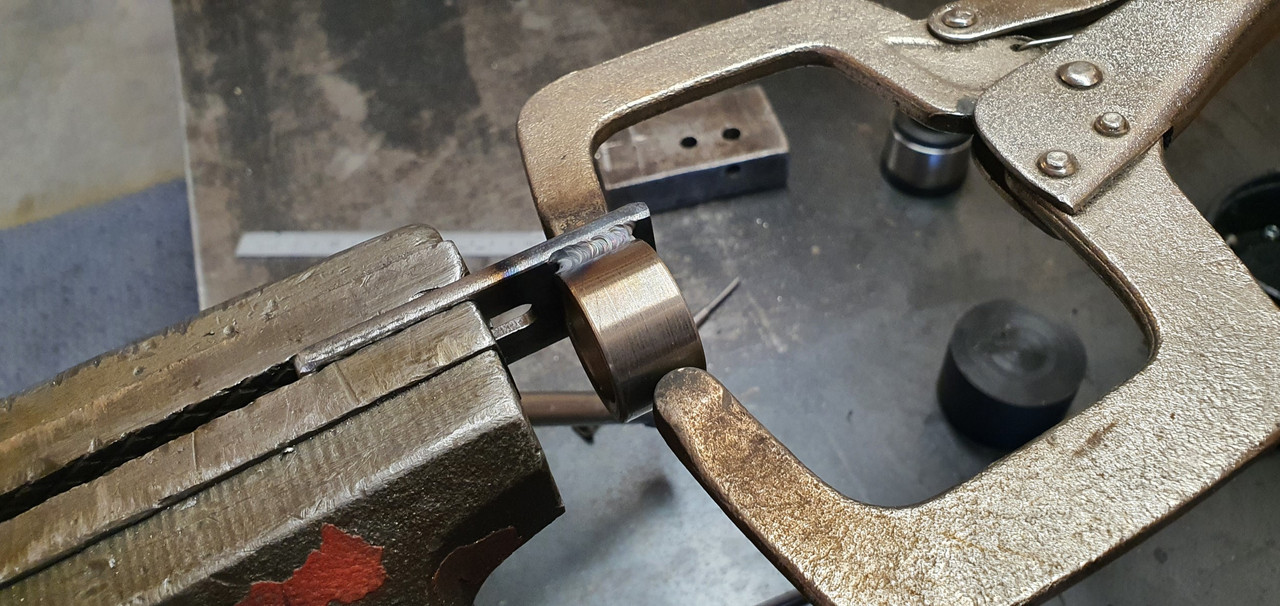
Then made a stainless cradle ..
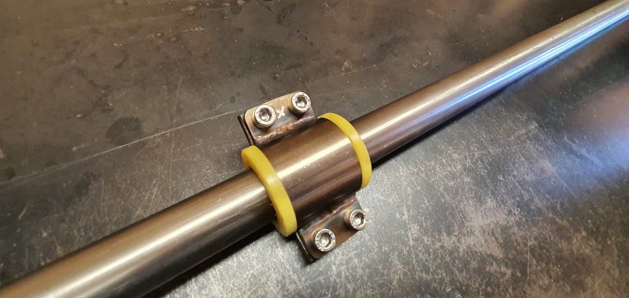
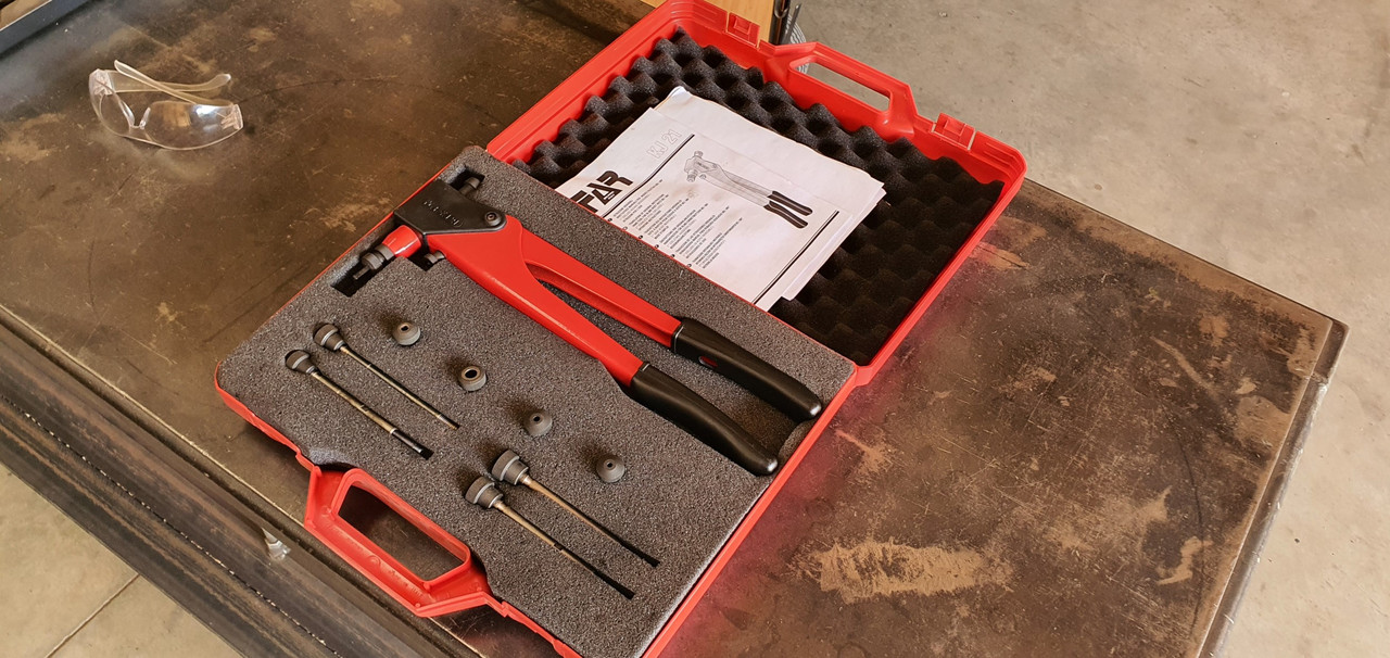
The cradle got some wings welded in place and I dug the rivnut tool out..
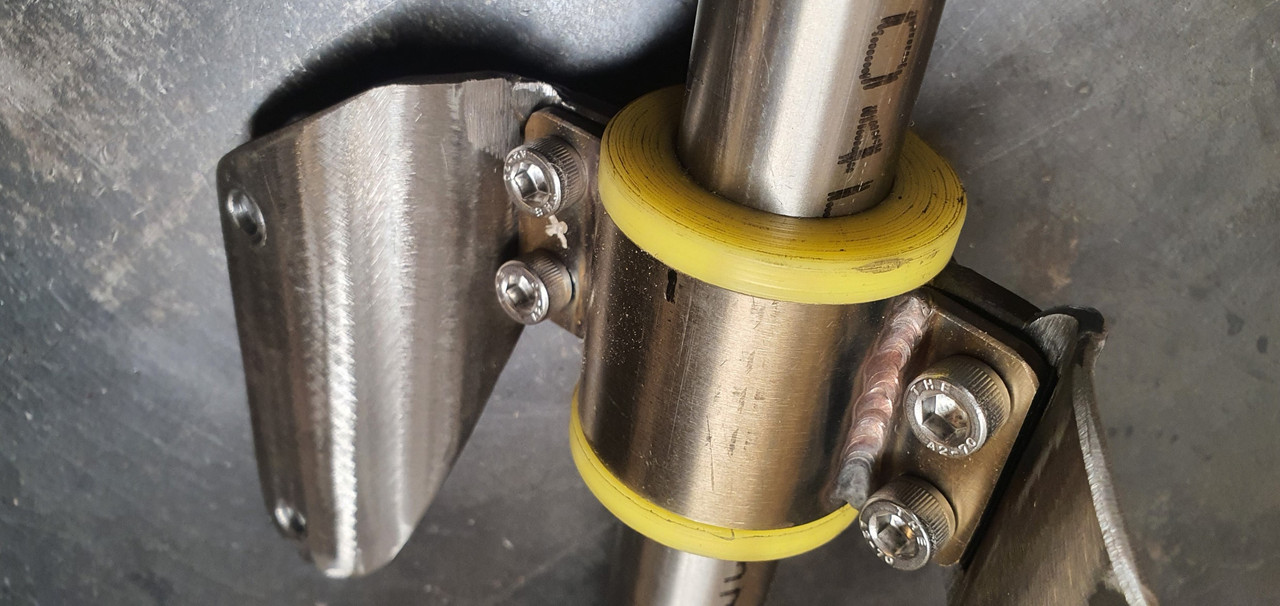
Mount now bolted in place in the tunnel I had to chop the last tube to the right length, weld on the end and bolt the universal in place..
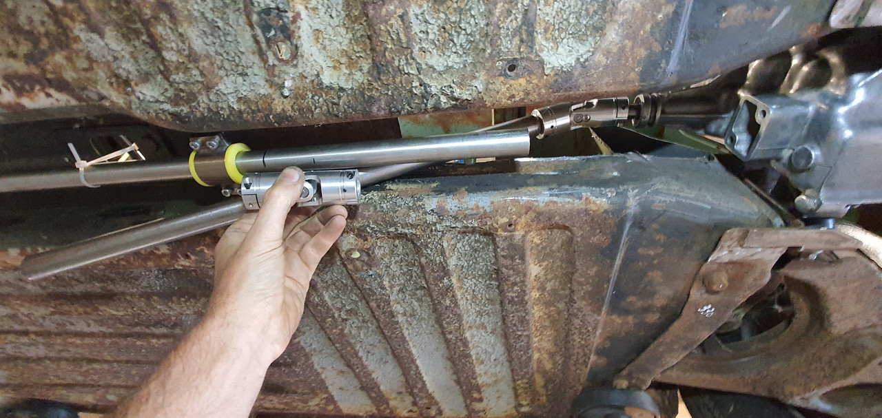
The front end below the shifter was was standard imp stuff and this is where problems popped up to throw a medium sized spanner in my workings. The side to side gearstick movement across the gate was minimal. Ridiculously so. Like about 1". Or 25mm in new money. Yet the fore and aft movement was about right. But quite stiff.
I was contemplating why this was so and what I could do to remedy this when I also noted that 1st gear was where 3rd was and 3rd was where 1st was.
Poos.
Four years ago when I had compared the Subaru gearshift pattern at the box to the imp unit I thought they were exactly the same. But I had not accounted for the reverse rotation taking place under the imp gearstick. Also I never really thought much about how little of rotation the Subaru box needed on its shifter shaft to shift the internal selector across the 3 rods. Its a tiny amount, like 3 degrees say. Whereas the Imp box has a shorter internal selector and requires more rotation at the shaft. Hence the Imps gearstick knob only moves a teeny bit when coupled to the Subaru box. But the Subaru box has a standard/similar amount of rod movement within (ie 1-2 and 3-4th) which was going to make things trickier to fix.
Simple linkage/leverage multiplications that is easier to see than explain.
Sorry if your brain hurts.
I had to hurt my brain a little bit to suss out a solution but there was only a little bit of smoke.
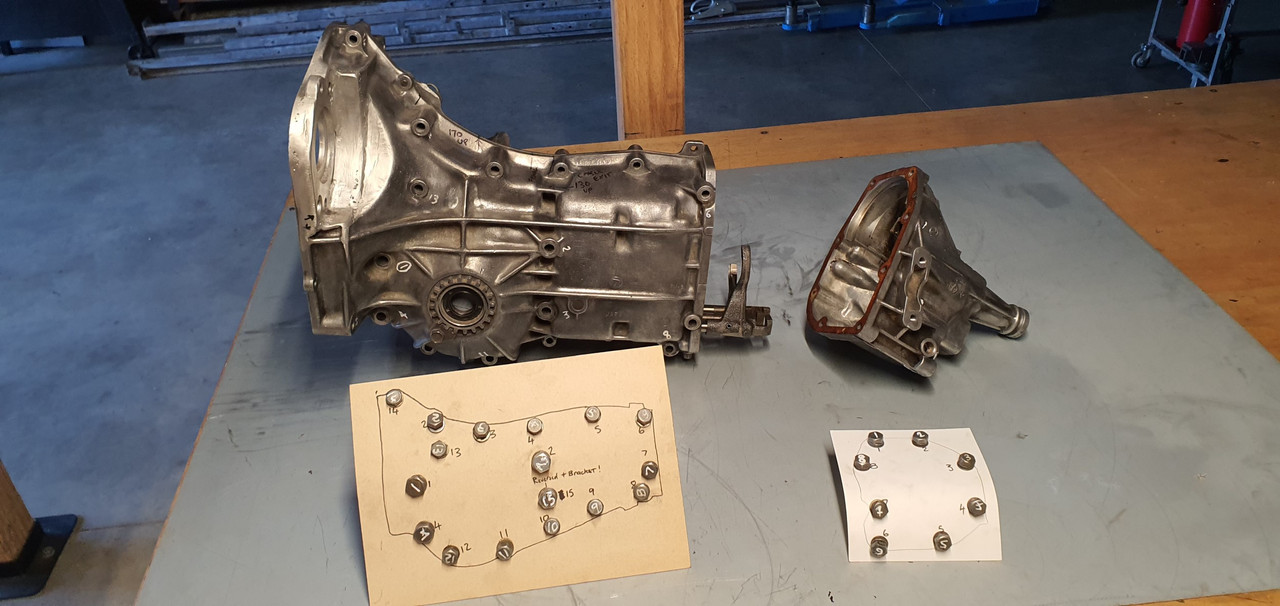
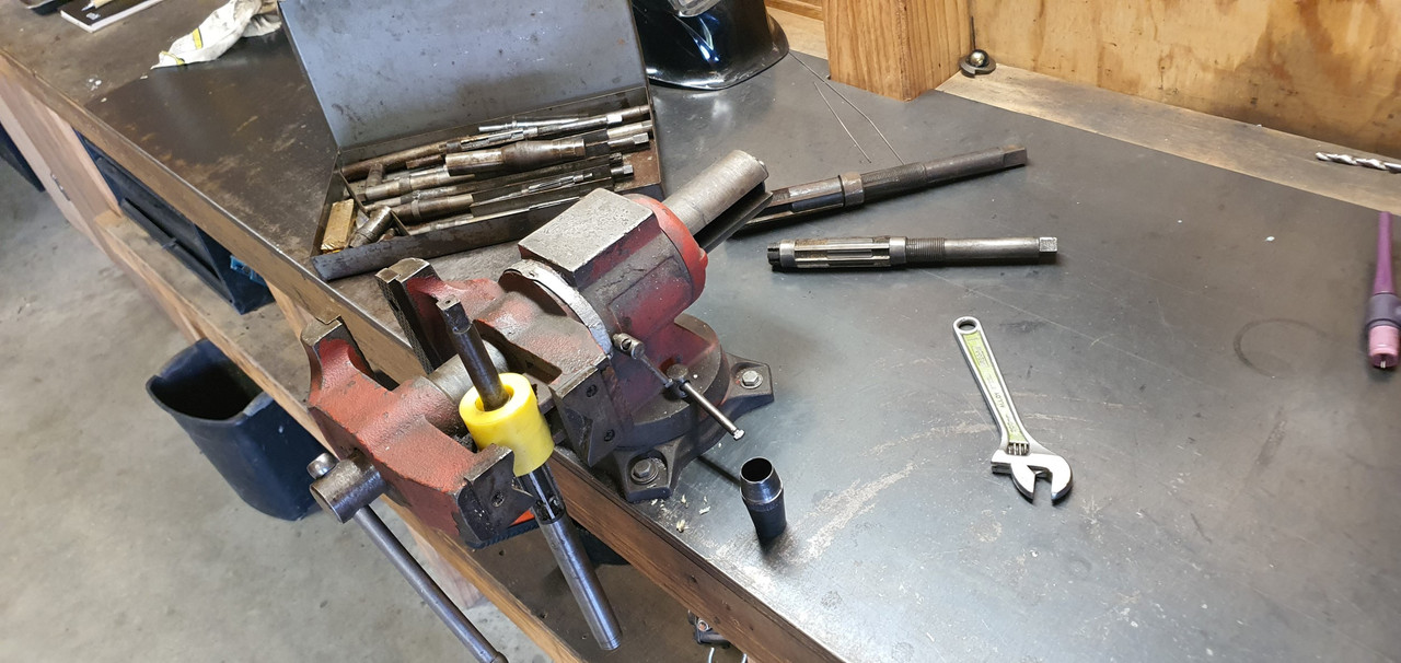
The reason the scooby box is different becomes obvious when you see the scooby shifter setup. Which luckily I can show you because last week thanks to a Subaru leone owner on oldschool.co.nz forum I was put onto a local fella to me who happens to have many old Leones and Brats kicking about his property and he had a spare leone front wheel drive box that I wanted (always handy just in case...)
His property is amazing!!! Long 4wd only driveway up to a ridgetop house with stunning views out over Tasman Bay. Old leones just kicking about...
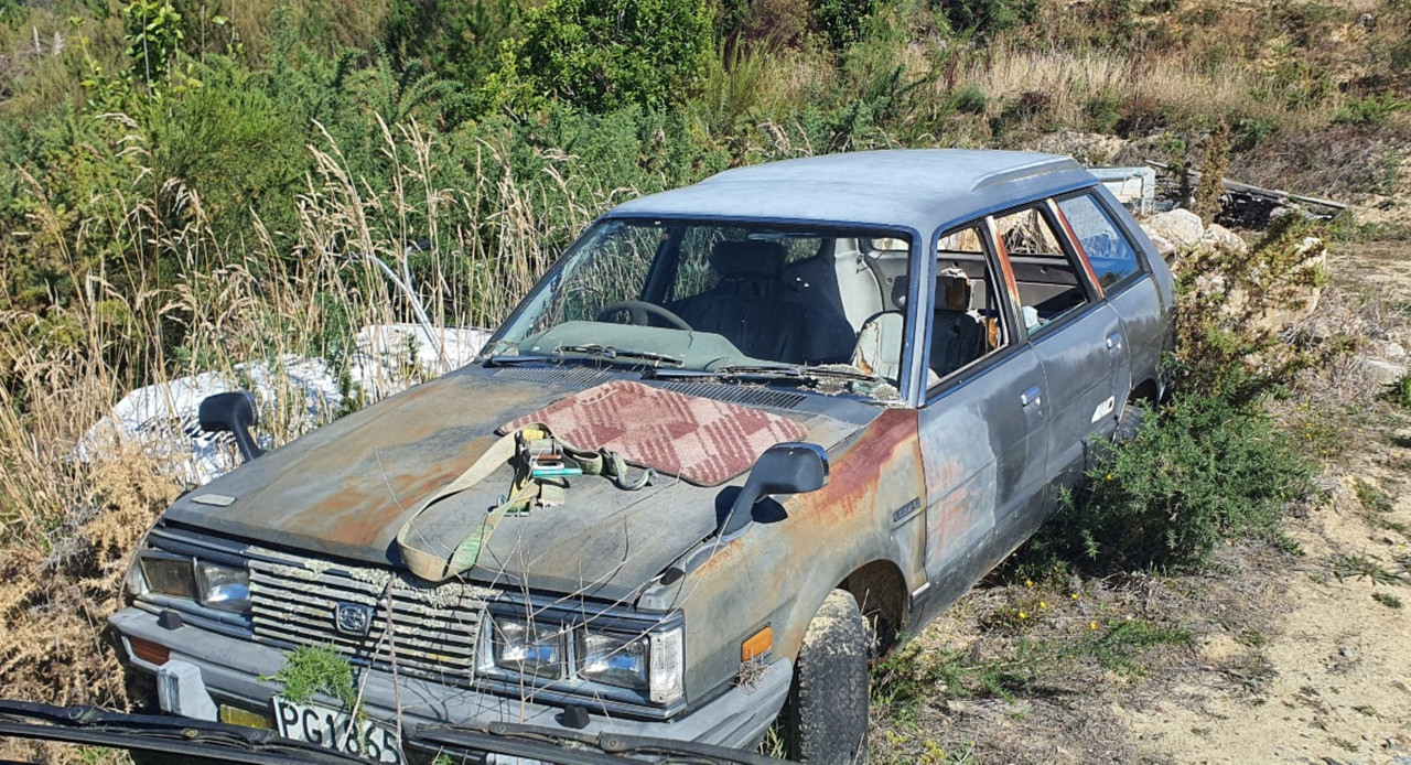
Luckily we have our trusty old 4wd Hiace and that became the days gearbox transporter...
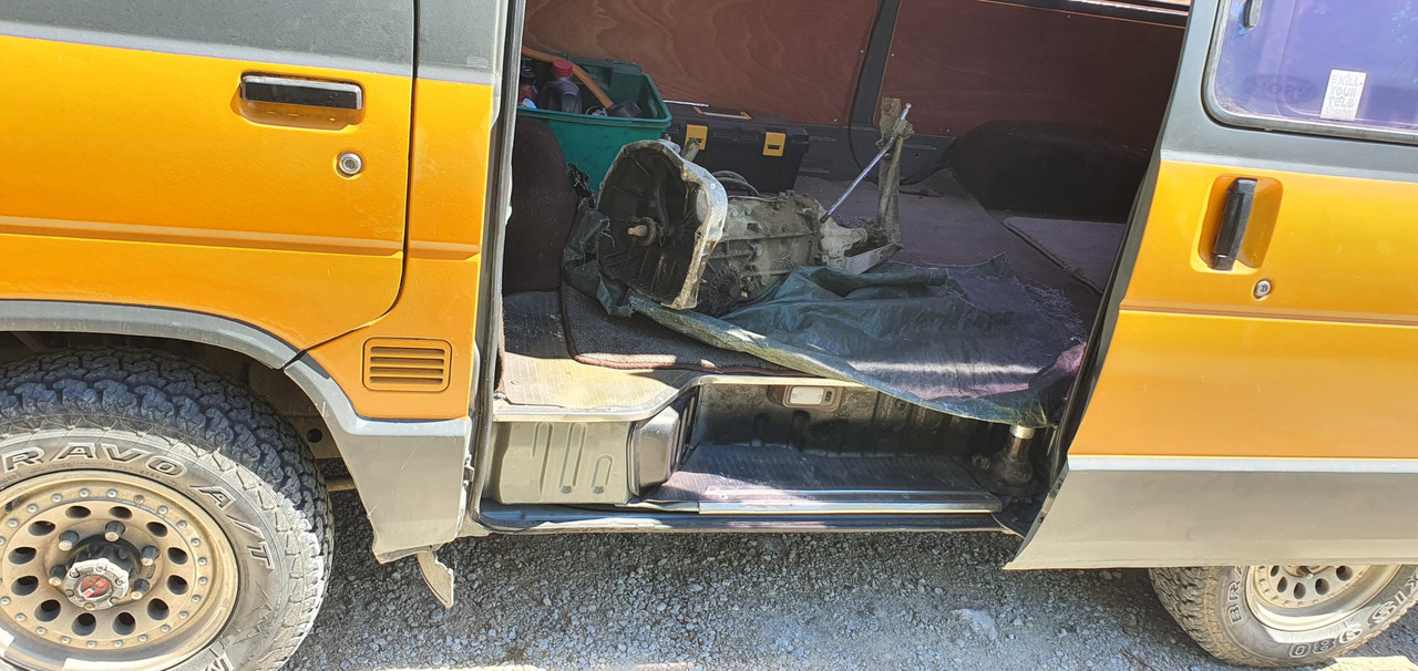
Box on bench. Look at that shifter mechanism...
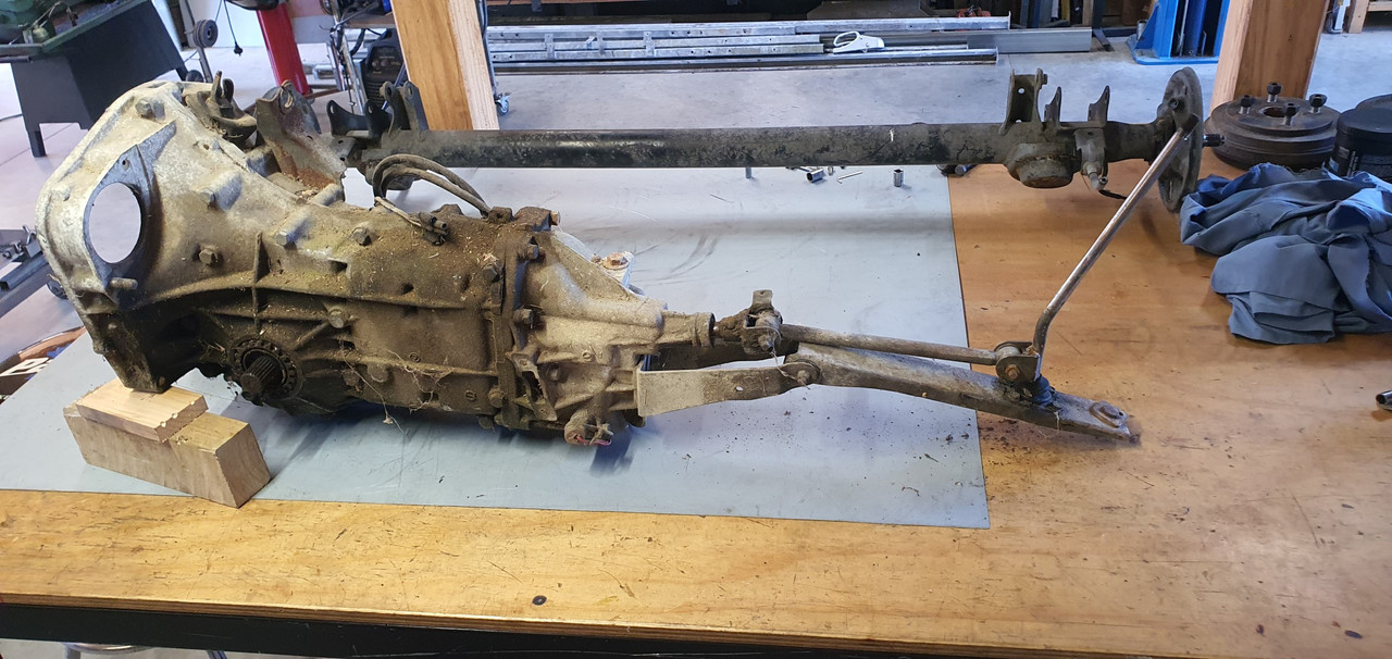
The shifter rod attached to the gearstick only rotates a tiny amount when the stick is moved sideways across the gate. But the rod moves 10mm in each direction when shifting for and aft. Simple. Robust. Very Subaru.
I can't copy it though because I have turned my box 180 degrees. No matter where I put my pivot point (below or above) I'll have one of the planes working backwards.
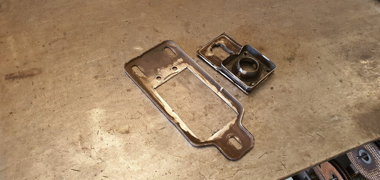
So I decided to build a new shifter base setup. The most important thing was to reverse the rotation so the gearstick pattern is correct. The imp pivot point needed raising to allow the offset shaft end to be rotated to above rather than below the centre line, so reversing the across gate movement. I would add the ability to adjust both rotation and lineal movement.
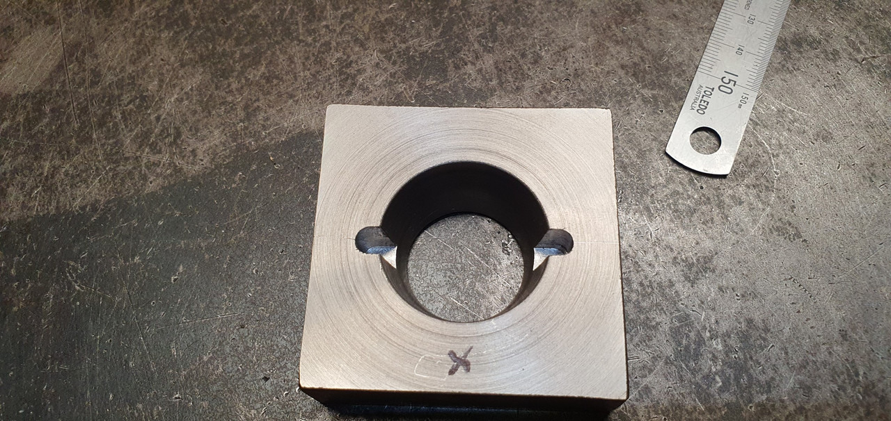
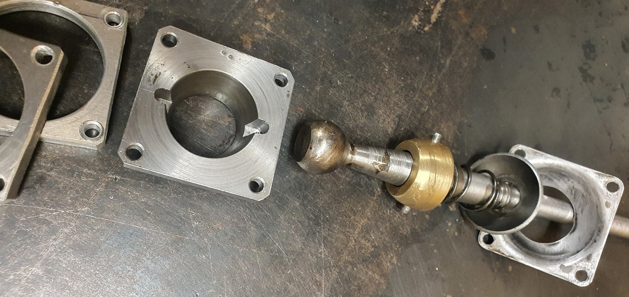
Started with a new pivot cup because I was not happy with the worn and Barried pressed steel item..
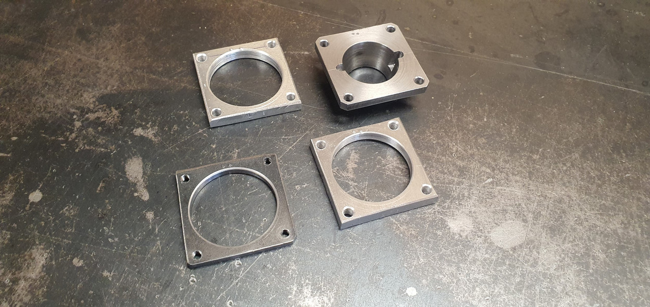
I dug out a large lump of steel bar...
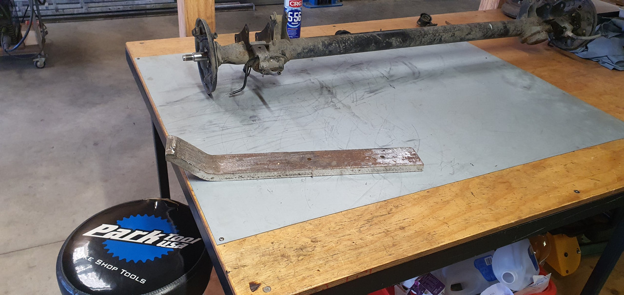
Chopped out a square and cleaned it up in the mill..
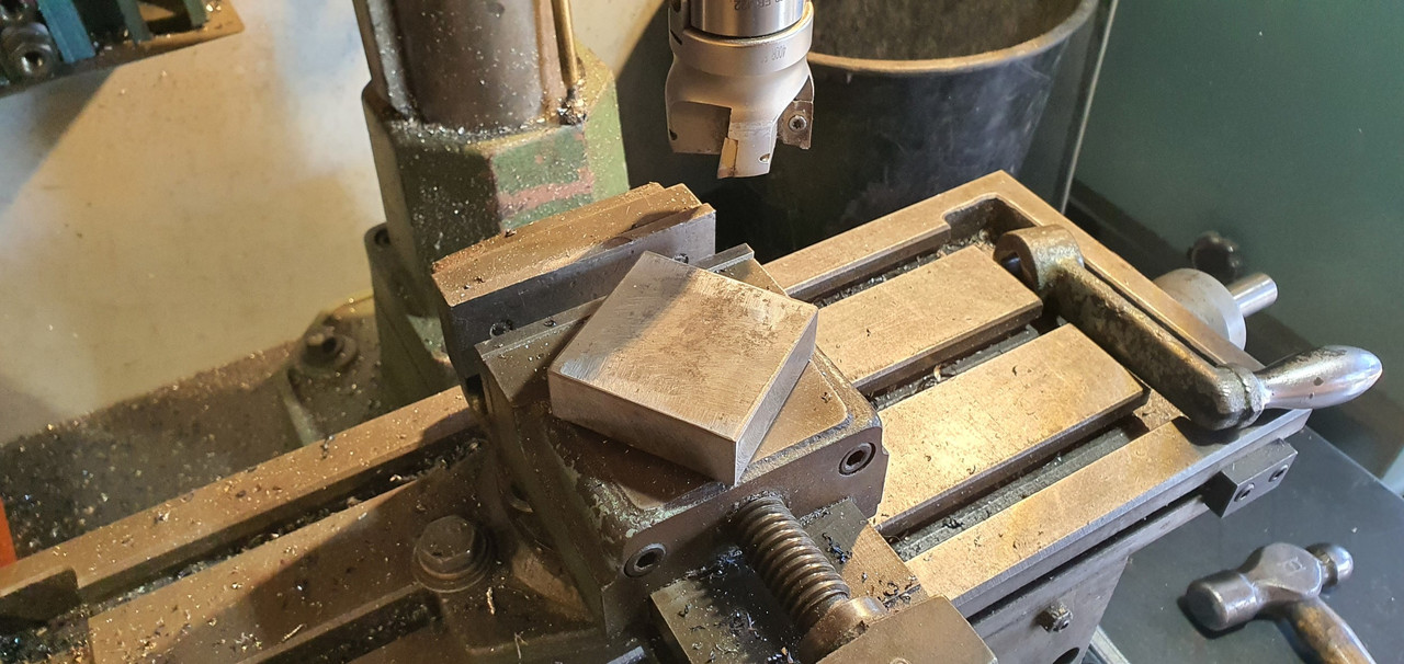
Big drill = big hole..
Rough machined out a cup shape. Cut a form in cardboard to suit the brass ball and used a die grinder bit to finish the shape...
Grinding paste time...
Slots for pivot pin..
Lightened the lump down..
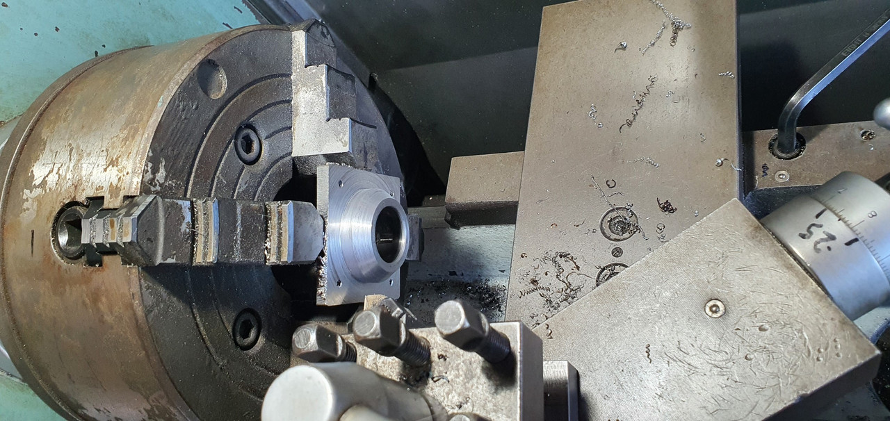
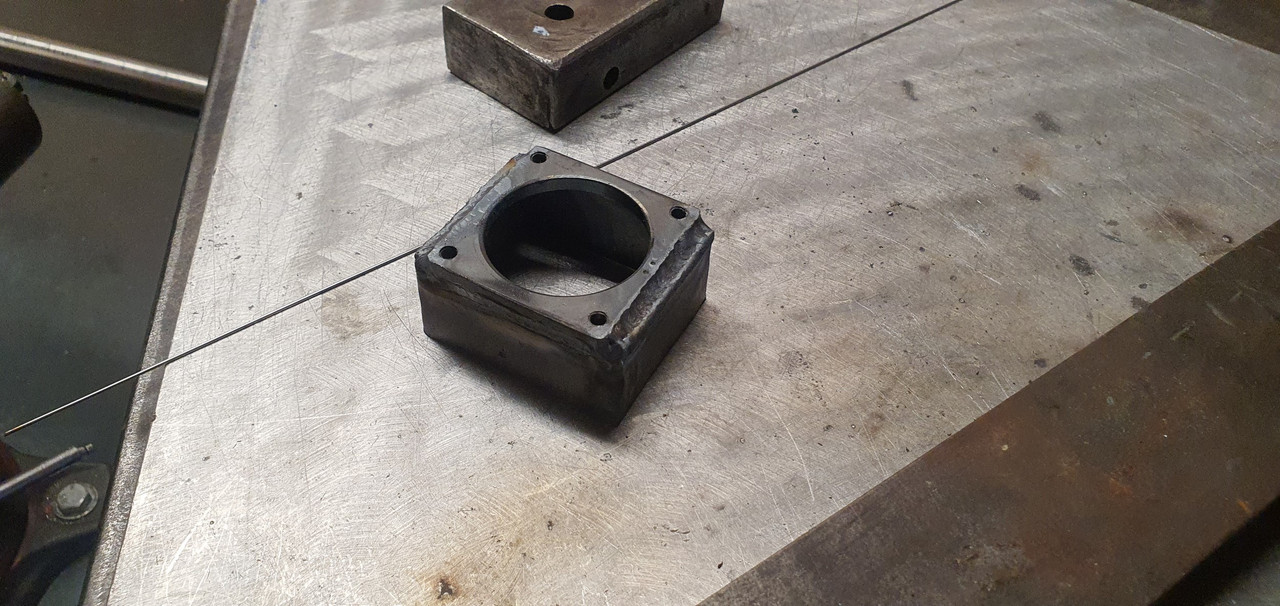
Built the shaft up with weld and machined it down so I could add a lower pivot point.
Milled some steel like so..
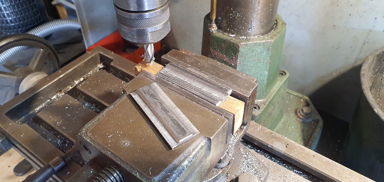
Welded a boss on..
New socket for shift lever ball end...
Cut out Barrys previous workmanship...
Machined up some spacers and a base plate..
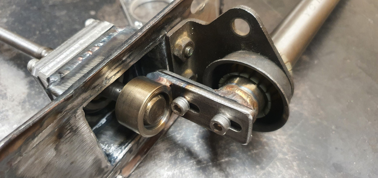
Welded up a little tower (my stainless and steel tig welding is definitely improving, helped muchly by realising that not being able to see what I'm doing does not help much and finally admitting to my age and buying some reading glasses....)
Welded tower to base..
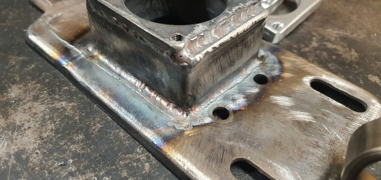
Now all together please...
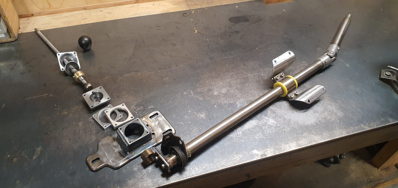
Bolted together. You can spot the adjustable rotation, which the spacers allow for, along with adjustable pivot point.
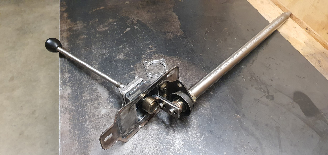
In place...
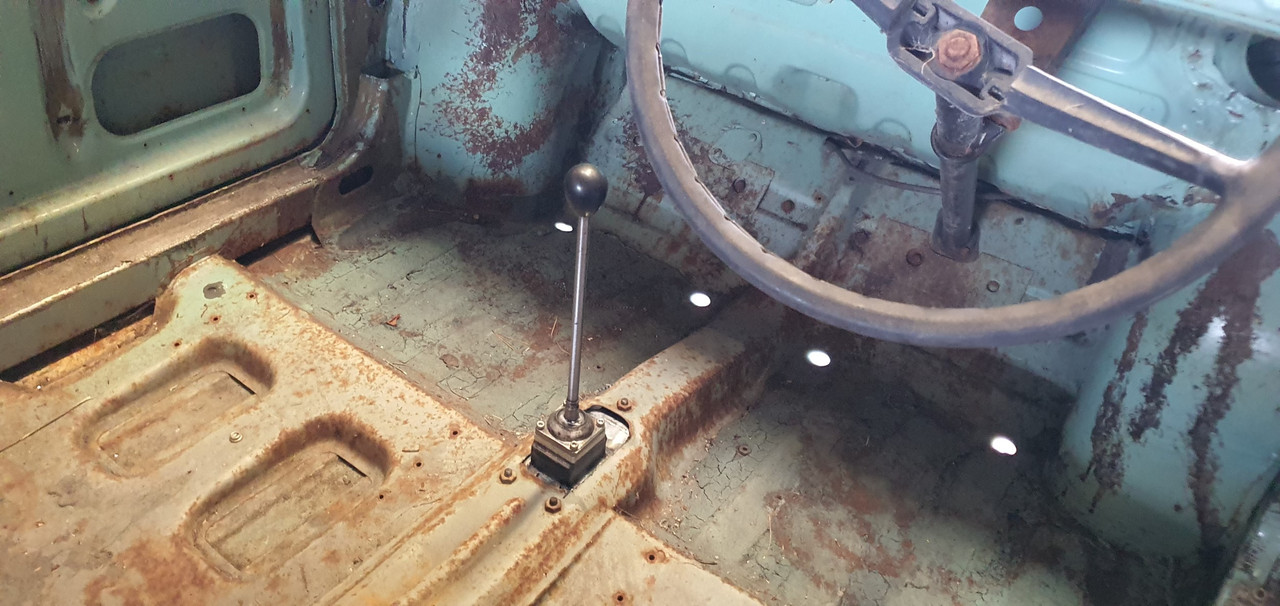
Yay- it works! The shift pattern is correct and the action is much smoother. The spring loaded indents on the internal gearbox shift rods are quite stiff, which I noted was the same on the other box with its stock shifter. Its a bit baulky to push past the synchro baulk rings into gear but I think will feel better when the gears are actually rotating. There's certainly no slop in the system and it feels very mechanical - not rubbery. I now note how much flex there is around the shifter base in the imps tunnel (granted a very rusty shell..) Its something I might just try to stiffen up on my blue Imp when fitting this lot in.
Phew. That was a little mini engineering mission I was not expecting but that's this project in general
I then started to fit the first part of the gearshift linkage. The first of those snazzy universal joints, handily available in a diameter to suit the shifter shaft on the Subaru box. I just needed to add a small locating hole for the grub screw...
Universal in place..
Engine and box were then bolted back into the car. This bit is so quick and easy when using the 'engine stand 2000'. It takes about 10 mins and I'm getting quicker. It'll be slower when there's shift linkage to undo and driveshafts to slip out of the way. But at least the main heavy awkward part is actually easy.
That lot in place I took some pics. Its neat to be able to look out from the one of the lounge room windows down onto the workshop floor and see this...
With that lot in place I was able to suss out the angles I could get away with, as shallow as possible and allowing for the handbrake mechanism.
I had this old imp gearstick assembly that a fellow Imp friend kindly posted over to me. Some previous owner of the car he got it from liked painting things. Everything. Multiple times...
I scrapped all the layers off, took it apart and cleaned off the dirty old grease. Discovered it had been cobbled together from two old shifter bases. It was originally a very early Imp unit when the very first cars had an automatic choke, which often proved problematic. Hillman then changed the cars over to a manual choke with a nifty little lever in front of the shifter. This mount had been added to the early base. Which means they must have chopped up a later baseplate to get the choke mount. Why they didn't just fit the entire newer base plate I don't know. But what I had in front of me was a frankenstein of base plates with barry spec welding and fixes, but also including a not too badly made bronze bush on the lever where there is normally a (wornout) plastic bush.
I had a couple of shift rods to choose from. I chose the least worn.
Moving back to the gearbox end I machined up some shaft ends from stainless bar to suit the universal joints. I had some stainless tube and welded the ends in place on the first shaft that runs from the gearbox universal down to the tunnel.
Now I needed a sturdy, slippery support to mount in place of the second universal joint. This will not only take back and forth movement on the shaft but also a bit of thrust loading created by the angle on the connecting shaft. I had already bought a lump of slippery hard engineering plastic with this application in mind when I had ordered the plastic for the flywheel thrust bearing a while back. It was bright yellow. Luckily not seen under the car as it would clash with the blue paint. I put a hole in it and machined the outside down.
Which also created a pile of pretty swarf..
Then reamed it out to 1"
Still a bit tight so out with the adjustable reamers..
until it was just right...
Then made a stainless cradle ..
The cradle got some wings welded in place and I dug the rivnut tool out..
Mount now bolted in place in the tunnel I had to chop the last tube to the right length, weld on the end and bolt the universal in place..
The front end below the shifter was was standard imp stuff and this is where problems popped up to throw a medium sized spanner in my workings. The side to side gearstick movement across the gate was minimal. Ridiculously so. Like about 1". Or 25mm in new money. Yet the fore and aft movement was about right. But quite stiff.
I was contemplating why this was so and what I could do to remedy this when I also noted that 1st gear was where 3rd was and 3rd was where 1st was.
Poos.
Four years ago when I had compared the Subaru gearshift pattern at the box to the imp unit I thought they were exactly the same. But I had not accounted for the reverse rotation taking place under the imp gearstick. Also I never really thought much about how little of rotation the Subaru box needed on its shifter shaft to shift the internal selector across the 3 rods. Its a tiny amount, like 3 degrees say. Whereas the Imp box has a shorter internal selector and requires more rotation at the shaft. Hence the Imps gearstick knob only moves a teeny bit when coupled to the Subaru box. But the Subaru box has a standard/similar amount of rod movement within (ie 1-2 and 3-4th) which was going to make things trickier to fix.
Simple linkage/leverage multiplications that is easier to see than explain.
Sorry if your brain hurts.
I had to hurt my brain a little bit to suss out a solution but there was only a little bit of smoke.
The reason the scooby box is different becomes obvious when you see the scooby shifter setup. Which luckily I can show you because last week thanks to a Subaru leone owner on oldschool.co.nz forum I was put onto a local fella to me who happens to have many old Leones and Brats kicking about his property and he had a spare leone front wheel drive box that I wanted (always handy just in case...)
His property is amazing!!! Long 4wd only driveway up to a ridgetop house with stunning views out over Tasman Bay. Old leones just kicking about...
Luckily we have our trusty old 4wd Hiace and that became the days gearbox transporter...
Box on bench. Look at that shifter mechanism...
The shifter rod attached to the gearstick only rotates a tiny amount when the stick is moved sideways across the gate. But the rod moves 10mm in each direction when shifting for and aft. Simple. Robust. Very Subaru.
I can't copy it though because I have turned my box 180 degrees. No matter where I put my pivot point (below or above) I'll have one of the planes working backwards.
So I decided to build a new shifter base setup. The most important thing was to reverse the rotation so the gearstick pattern is correct. The imp pivot point needed raising to allow the offset shaft end to be rotated to above rather than below the centre line, so reversing the across gate movement. I would add the ability to adjust both rotation and lineal movement.
Started with a new pivot cup because I was not happy with the worn and Barried pressed steel item..
I dug out a large lump of steel bar...
Chopped out a square and cleaned it up in the mill..
Big drill = big hole..
Rough machined out a cup shape. Cut a form in cardboard to suit the brass ball and used a die grinder bit to finish the shape...
Grinding paste time...
Slots for pivot pin..
Lightened the lump down..
Built the shaft up with weld and machined it down so I could add a lower pivot point.
Milled some steel like so..
Welded a boss on..
New socket for shift lever ball end...
Cut out Barrys previous workmanship...
Machined up some spacers and a base plate..
Welded up a little tower (my stainless and steel tig welding is definitely improving, helped muchly by realising that not being able to see what I'm doing does not help much and finally admitting to my age and buying some reading glasses....)
Welded tower to base..
Now all together please...
Bolted together. You can spot the adjustable rotation, which the spacers allow for, along with adjustable pivot point.
In place...
Yay- it works! The shift pattern is correct and the action is much smoother. The spring loaded indents on the internal gearbox shift rods are quite stiff, which I noted was the same on the other box with its stock shifter. Its a bit baulky to push past the synchro baulk rings into gear but I think will feel better when the gears are actually rotating. There's certainly no slop in the system and it feels very mechanical - not rubbery. I now note how much flex there is around the shifter base in the imps tunnel (granted a very rusty shell..) Its something I might just try to stiffen up on my blue Imp when fitting this lot in.
Phew. That was a little mini engineering mission I was not expecting but that's this project in general
-
911hillclimber
- Nurse, I think I need some assistance
- Posts: 18924
- Joined: Mon Mar 10, 2008 6:26 pm
- Location: West Midlands
Re: 1965 Hillman Imp soon with flat six from a Honda
Good going to say the least!
These builds are a string of these challenges, but that is the fun bit. You will be bored when it's all done!
Great to see and the 'house-view' of the car with engine in I'm sure is a n inspiration and motivates.
When i did my LOLA-Porsche hillclimb car the scenario was very similar but less complicated, the last look at the car and the progress each night (mostly) warmed my heart.
You are closing in on the final chapter, looking forward to the next escapades..
73T 911 Coupe, road/hillclimber 3.2L
Lola t 492 / 3.2 hillclimb racer
Boxster 987 Gen II 2.9
Lola t 492 / 3.2 hillclimb racer
Boxster 987 Gen II 2.9
Re: 1965 Hillman Imp soon with flat six from a Honda
Yes I'm certainly getting closer to pulling the Datsun from my imp and lobbing this lot in. Driveshafts next. Its fun- I'm really enjoying this stage, no doubt made better by knowing that the engine is a runner and so far seems to be behaving itself with the short amount of time I've ran it.
-
sladey
- Nurse, I think I need some assistance
- Posts: 8728
- Joined: Sat Apr 23, 2005 9:08 pm
- Location: Nottingham, UK
Re: 1965 Hillman Imp soon with flat six from a Honda
Great stuff and nice engineering
The simple things you see are all complicated
I look pretty young but I'm just backdated yeah
I look pretty young but I'm just backdated yeah
-
Nine One One
- Put a fork in me, I'm done!
- Posts: 1635
- Joined: Fri Mar 01, 2013 11:45 am
- Location: Kernow - good old Cornwall
Re: 1965 Hillman Imp soon with flat six from a Honda
Absolute craftsmanship - really enjoying this build coming together and your skills!
Re: 1965 Hillman Imp soon with flat six from a Honda
That took a couple reads, but think I get it! Really, really good, Alex! I'm sure you are sketching a few parts of the design process. Please add one or two to really simplify how it's going together
Re: 1965 Hillman Imp soon with flat six from a Honda
Sorry for late reply Steven. I have a small note book full of sketches for this project from the very start. But none of them will make it much easier for you to understand