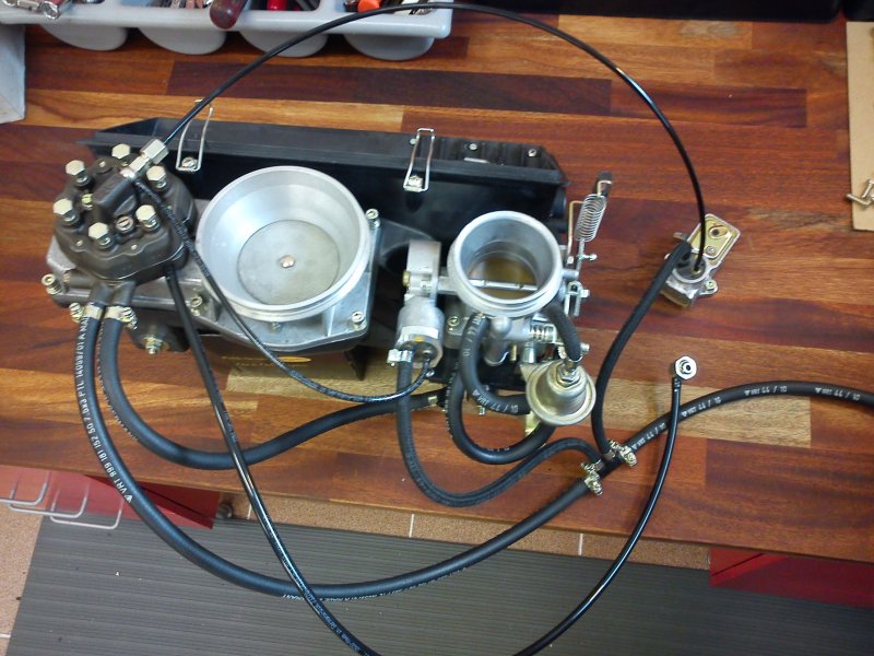
Fuel lines for 1974 2.7 CIS
Posted: Sun Aug 28, 2016 10:19 pm
As described in my restoration thread I am struggling to work out the best way of putting the fuel lines back on my restoration.
My car is a 1974 2.7 CIS which appear to have some of the parts from the -74 PET drawings and some from the 75- drawings.
It may be that the car has been messed around with at some point but I suspect it was built in a period where a lot of the methodology at Porsche was changing daily.
I propose to write this post and re-edit it as I find out some of the answers to my questions and as I get more info - but for the moment here goes. Please jump in with suggestions, all advice is much appreciated as always.
Although I do wish to retain some originality, I am happy to make changes where there is a reliability or safety improvement to be made.
So lets start at the beginning and discuss the tank to pump.
Fuel tank - my original fuel tank had push fittings as shown here

whereas my replacement Dansk tank has one push fitting and one threaded connector - so this is a difference I will need to accomodate.
PET shows

So I am pretty certain my original tank was option 2 for the tank.
The first fuel lines are shown as items 31 (280mm of 999 181 168 50 named 'hose' ) for the intake,
and 32 (999 181 152 50 named 'hose C 7,5 X 13,5 ) for the start of the return line.
Then the fuel intake and returns lines (items 38 and 40) are shown as 911 356 067 01 and 911 356 062 03 respectively.
Both these parts are shown as NLA as far as I can tell so I probably need to take a later solution.
My intake and return lines looks as follows, with the return still having the tank connection pipe fitted:

Now I have been told that these don't sound like the original lines, however I tend to disagree and think they are original.
I don't want to refit this 40+ year old lines so I am looking for options.
I think that some of the later lines have fittings built into them at both ends to prevent having to rely on jubilee clip style fittings.
Any thoughts ?
So here is the fuel pump as fitted above the LS rear wheel arch.

And here is the -1974 PET drawing.

So it looks like the correct -1974 pump, fitted to the correct -1974 right angled bracket. The pump has the check valve incorporated in the banjo union which seems correct.
The intake has passed through three separate pipes and four jubilee clip joins to reach the pump!
I have sourced a NOS pump which I intend to use with the check valve.

Questions here are:
Should I consider moving the pump to the front of the car ( less original but probably a better solution )?
If I leave the pump here what are the better pipe routing options?
Another confusion is that the fuel pump feed and the return line then pass through to the engine bay from the wheel arch area through two rigid steel pipes ( that's four more jubilee clips and four more joins ), before the fuel pump feed passes to the accumulator, and the engine return connects to the return line.
This is in the hazy area of the PET diagram where the pipes 13 and 15 go dotted. The PET guide possibly hints that the pipes go through but I definitely have two steel rigid pipes and extra jubilee clips!
Now for the life of me I cannot seem to find this rigid steel lines in the PET guide - where are they? - help!
Here is the accumulator and filter in situ, showing the through bulkhead connections in the bottom right.

As you can see the fuel filter bracket and arrangement is as per the 75- PET guide.

I clearly have fuel line 15, 930 356 076 01 and new replacements are available.
The fuel line identified as 11, 911 356 066 33 is a different setup to my car, however it appears to be a NLA part again.
The second port of my accumulator has a right angled fitting to barb connector - not sure what the original Porsche number would be for this yet.
Once I get towards the engine I think the fuel lines become a bit clearer.
To be continued..
If anyone has any suggestions for any of the parts shown please fell free to comment.
I'm guessing I need to establish what I am doing with the tunnel lines and work outwards from there.
So what do people use for the tunnel lines now?
I'll stop here for the moment, but things get a bit stranger as from here on my car behaves more like a 75- PET car before the CIS system is back to a -74 setup. For example the accumulator bracket fitted to my car is definitely the one shown in the 75- PET drawing!
My car is a 1974 2.7 CIS which appear to have some of the parts from the -74 PET drawings and some from the 75- drawings.
It may be that the car has been messed around with at some point but I suspect it was built in a period where a lot of the methodology at Porsche was changing daily.
I propose to write this post and re-edit it as I find out some of the answers to my questions and as I get more info - but for the moment here goes. Please jump in with suggestions, all advice is much appreciated as always.
Although I do wish to retain some originality, I am happy to make changes where there is a reliability or safety improvement to be made.
So lets start at the beginning and discuss the tank to pump.
Fuel tank - my original fuel tank had push fittings as shown here

whereas my replacement Dansk tank has one push fitting and one threaded connector - so this is a difference I will need to accomodate.
PET shows

So I am pretty certain my original tank was option 2 for the tank.
The first fuel lines are shown as items 31 (280mm of 999 181 168 50 named 'hose' ) for the intake,
and 32 (999 181 152 50 named 'hose C 7,5 X 13,5 ) for the start of the return line.
Then the fuel intake and returns lines (items 38 and 40) are shown as 911 356 067 01 and 911 356 062 03 respectively.
Both these parts are shown as NLA as far as I can tell so I probably need to take a later solution.
My intake and return lines looks as follows, with the return still having the tank connection pipe fitted:

Now I have been told that these don't sound like the original lines, however I tend to disagree and think they are original.
I don't want to refit this 40+ year old lines so I am looking for options.
I think that some of the later lines have fittings built into them at both ends to prevent having to rely on jubilee clip style fittings.
Any thoughts ?
So here is the fuel pump as fitted above the LS rear wheel arch.

And here is the -1974 PET drawing.

So it looks like the correct -1974 pump, fitted to the correct -1974 right angled bracket. The pump has the check valve incorporated in the banjo union which seems correct.
The intake has passed through three separate pipes and four jubilee clip joins to reach the pump!
I have sourced a NOS pump which I intend to use with the check valve.

Questions here are:
Should I consider moving the pump to the front of the car ( less original but probably a better solution )?
If I leave the pump here what are the better pipe routing options?
Another confusion is that the fuel pump feed and the return line then pass through to the engine bay from the wheel arch area through two rigid steel pipes ( that's four more jubilee clips and four more joins ), before the fuel pump feed passes to the accumulator, and the engine return connects to the return line.
This is in the hazy area of the PET diagram where the pipes 13 and 15 go dotted. The PET guide possibly hints that the pipes go through but I definitely have two steel rigid pipes and extra jubilee clips!
Now for the life of me I cannot seem to find this rigid steel lines in the PET guide - where are they? - help!
Here is the accumulator and filter in situ, showing the through bulkhead connections in the bottom right.

As you can see the fuel filter bracket and arrangement is as per the 75- PET guide.

I clearly have fuel line 15, 930 356 076 01 and new replacements are available.
The fuel line identified as 11, 911 356 066 33 is a different setup to my car, however it appears to be a NLA part again.
The second port of my accumulator has a right angled fitting to barb connector - not sure what the original Porsche number would be for this yet.
Once I get towards the engine I think the fuel lines become a bit clearer.
To be continued..
If anyone has any suggestions for any of the parts shown please fell free to comment.
I'm guessing I need to establish what I am doing with the tunnel lines and work outwards from there.
So what do people use for the tunnel lines now?
I'll stop here for the moment, but things get a bit stranger as from here on my car behaves more like a 75- PET car before the CIS system is back to a -74 setup. For example the accumulator bracket fitted to my car is definitely the one shown in the 75- PET drawing!