519 Gearbox Rebuild

Porsche 356 Virtual home

Moderators: 58A - 71E, Helen

58A - 71E
Put a fork in me, I'm done!
Posts: 1842
Joined: Tue Nov 28, 2006 1:49 pm
Location: Yorkshire

519 Gearbox Rebuild

Post by 58A - 71E »

Thought I’d share my recent experiences of rebuilding my Gearbox. I share this not as a definitive how to, more a record of what I did – if anyone spots an error PLEASE let me know!

The first task is obviously to remove it from the car. I won’t go into detail here, except to say it is a real pain, as the engine has to come out, then disconnect all the brake lines and cables, before then removing the gearbox.

Here it is removed, with axle tubes removed as well:

Image

Image
James

'58 356A 1600n
'71 911E 2,2


#0335
58A - 71E
Put a fork in me, I'm done!
Posts: 1842
Joined: Tue Nov 28, 2006 1:49 pm
Location: Yorkshire

Post by 58A - 71E »

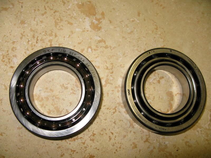
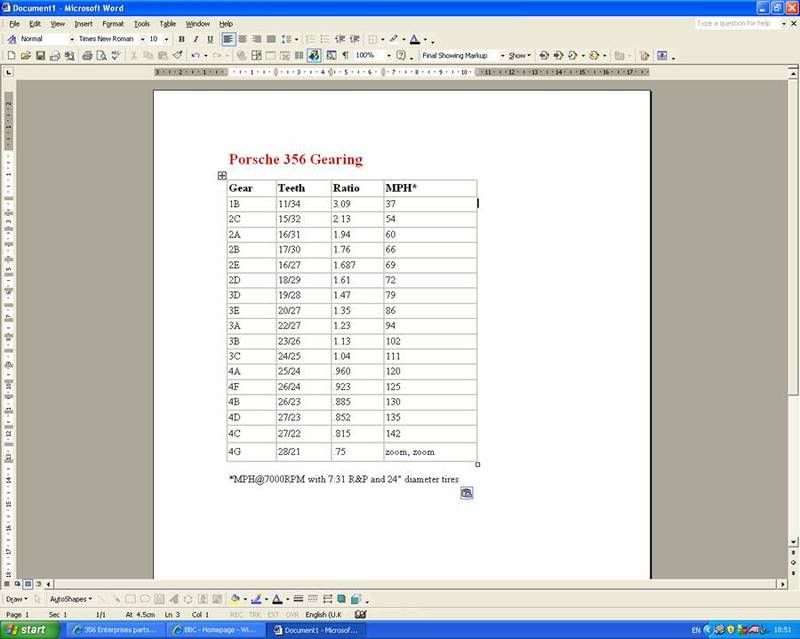
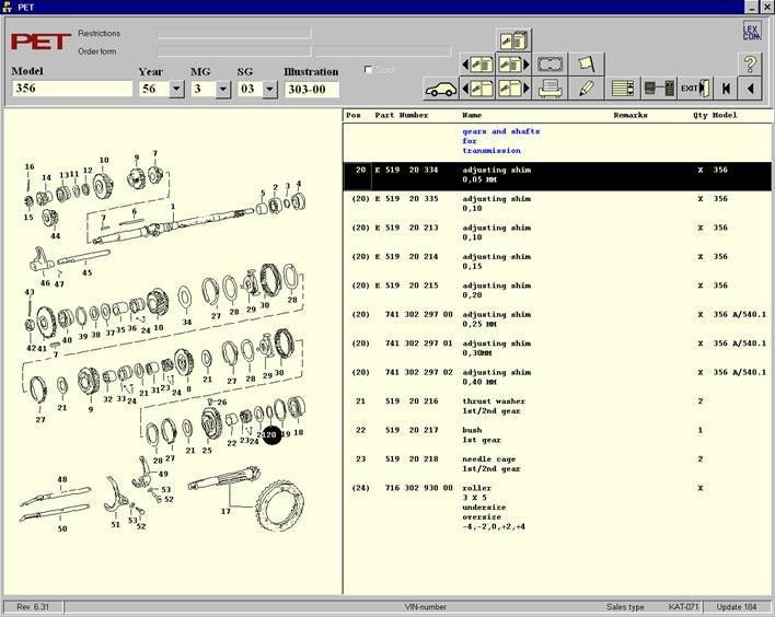
I had to then decipher what type of GearBox (GB) I actually had in the car. I knew I should have a 644 type tunnel box, but that definitely wasn’t what I had. There is some really good info in the 356 Porsche Technical and Restoration Guide vol.1 (the collection of 356 registry articles) about the differences between them all and also here – taken from Stoddard catalogue.

Image

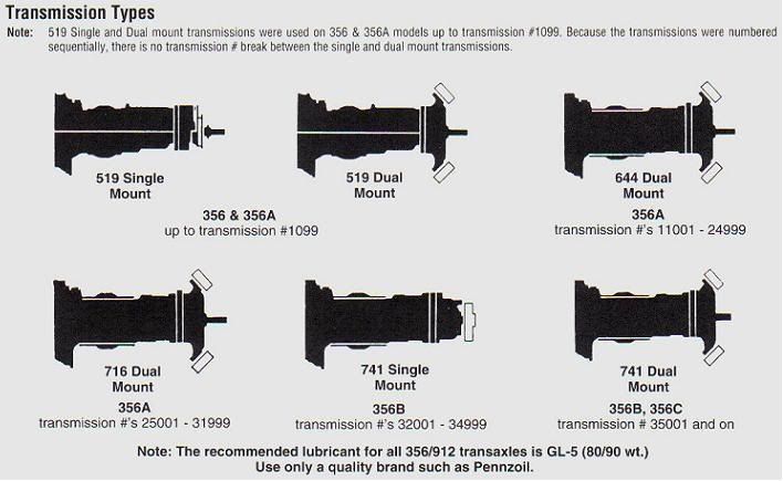
Although it should say 519 up to GB No 10999 not 1099 :roll:
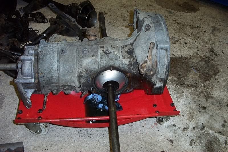
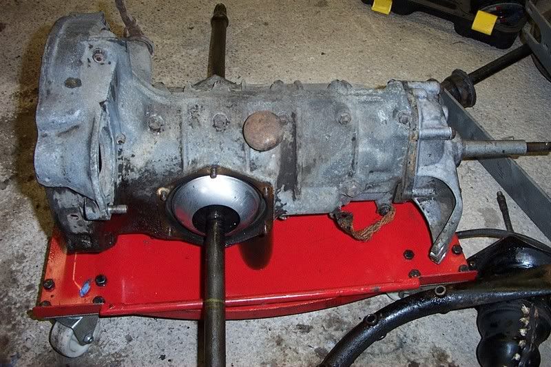
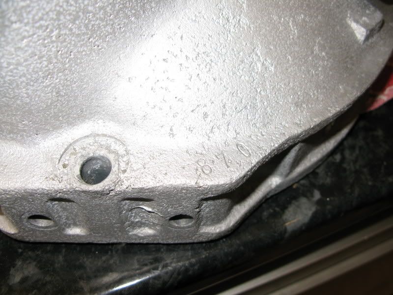
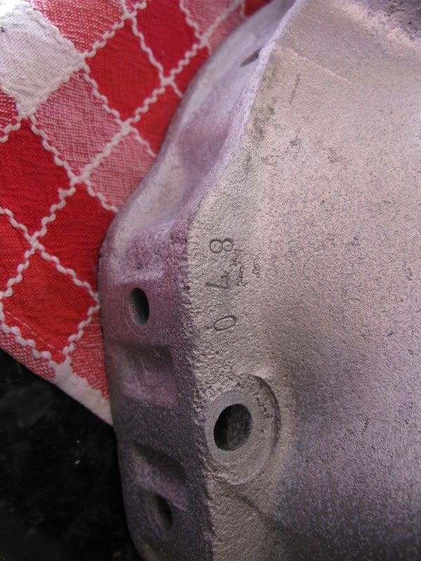
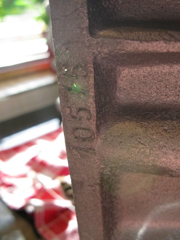
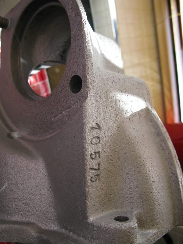
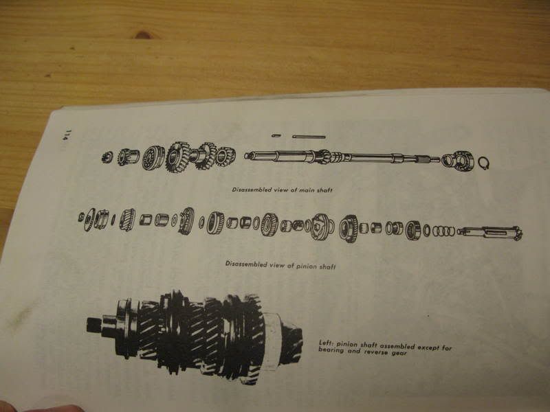
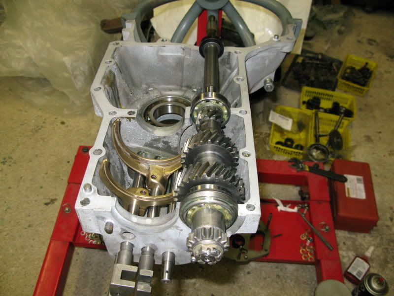
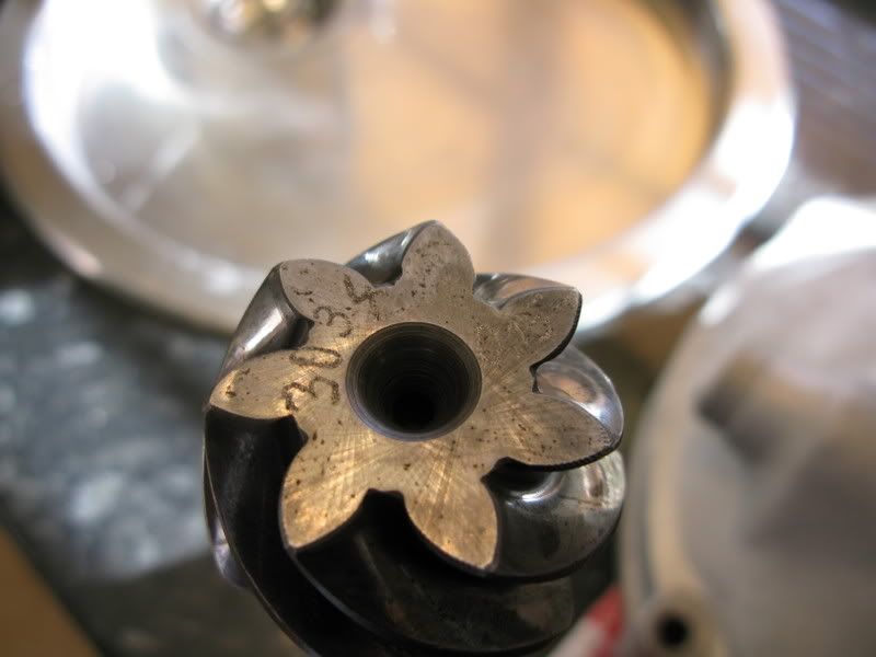
From this I was able to identify my GB number 10575 as a late split case 519 (probably from a 1956 T1 A) with a magnesium case, steel intermediate plate and aluminium dual mount nose cone.

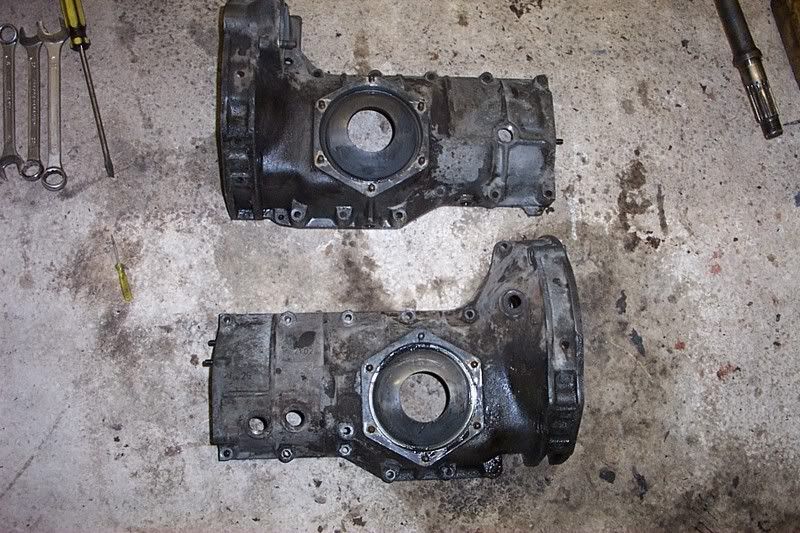
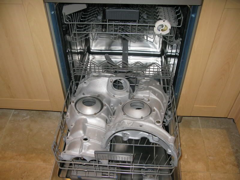
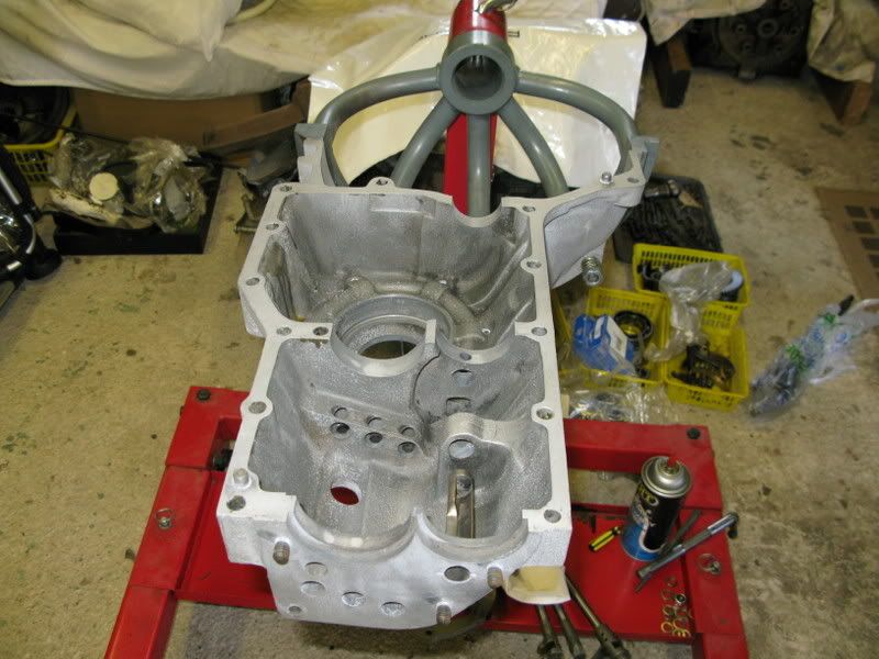
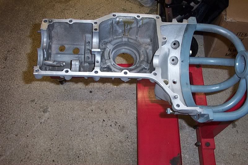
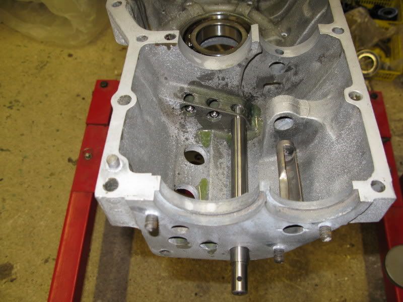
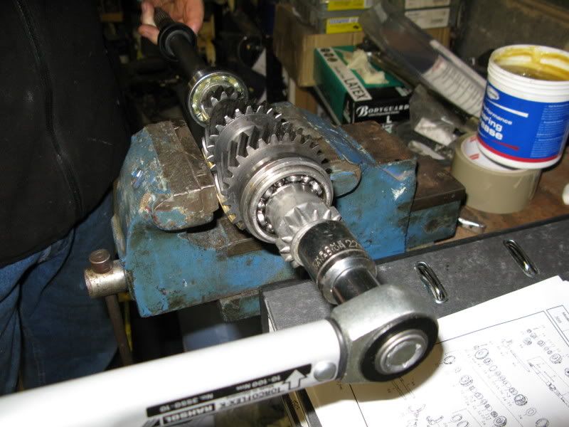
Dismantling was pretty straightforward, see a nut and undo it! What I didn’t do, and should have done, was to measure the thickness of all the gaskets I removed. This would have proved a useful reference later on (2 years later in fact!) when I got around to rebuilding it.

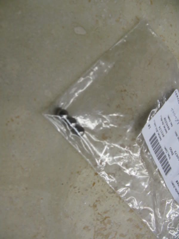
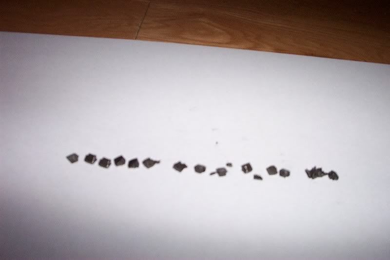
I found this lot in the drain plug which looked a bit ominous!

Image

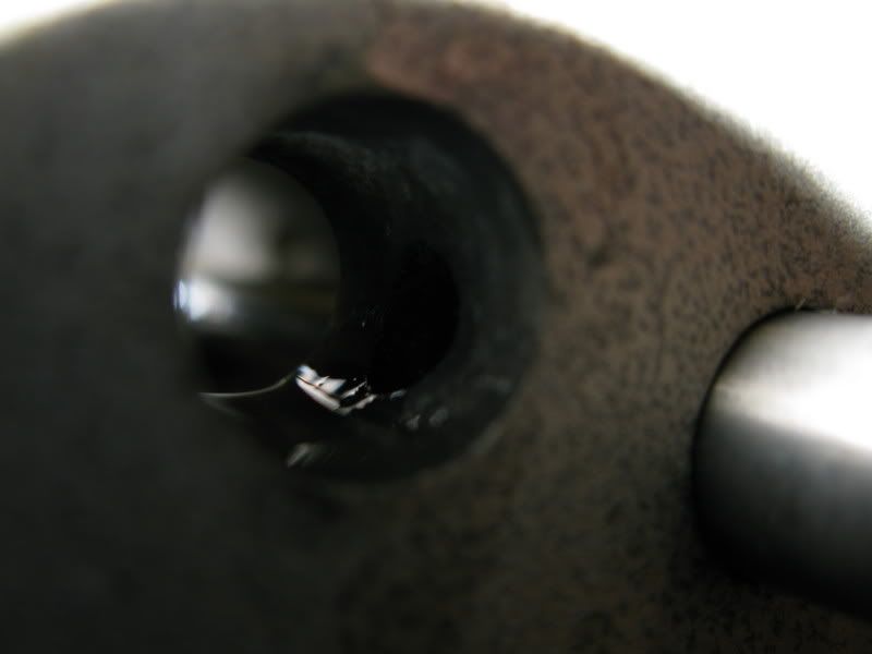
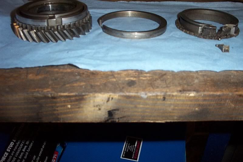
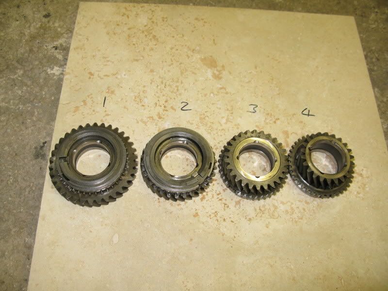
Second gear had always been a bit “dodgy” but just before taking it off the road it was proving to be really difficult to engage.

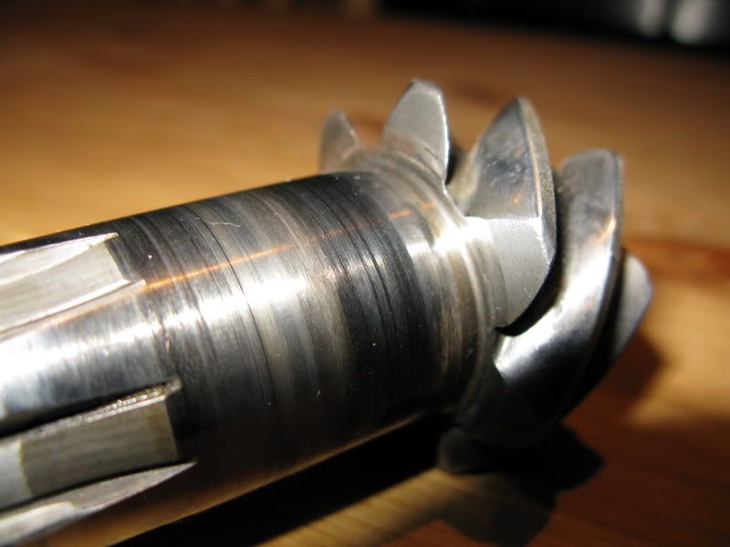
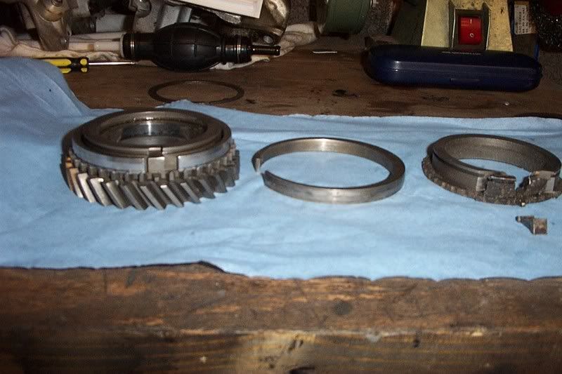
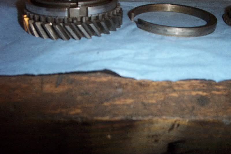
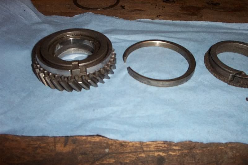
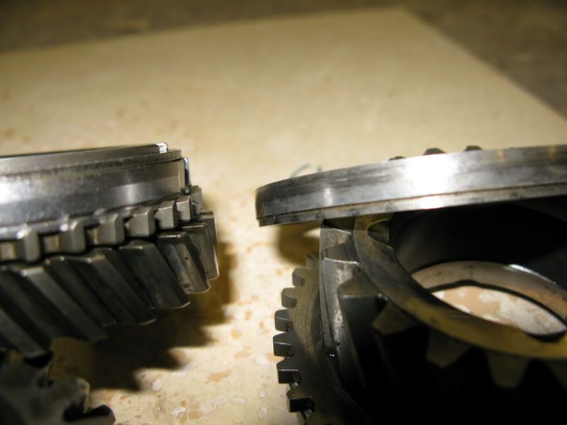
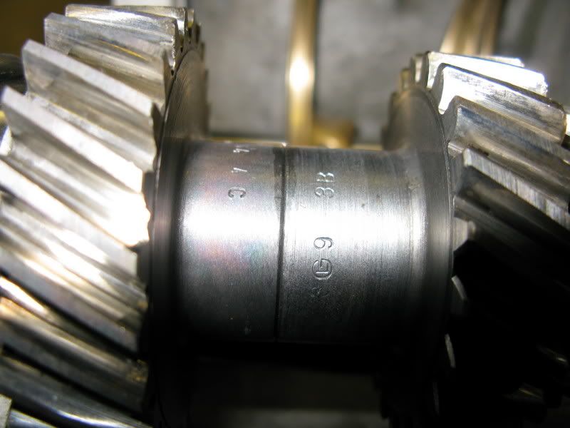
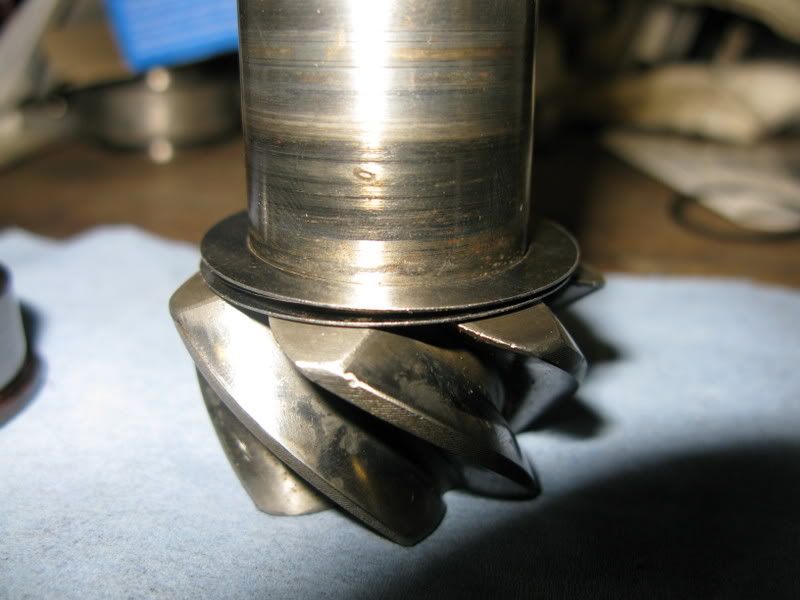
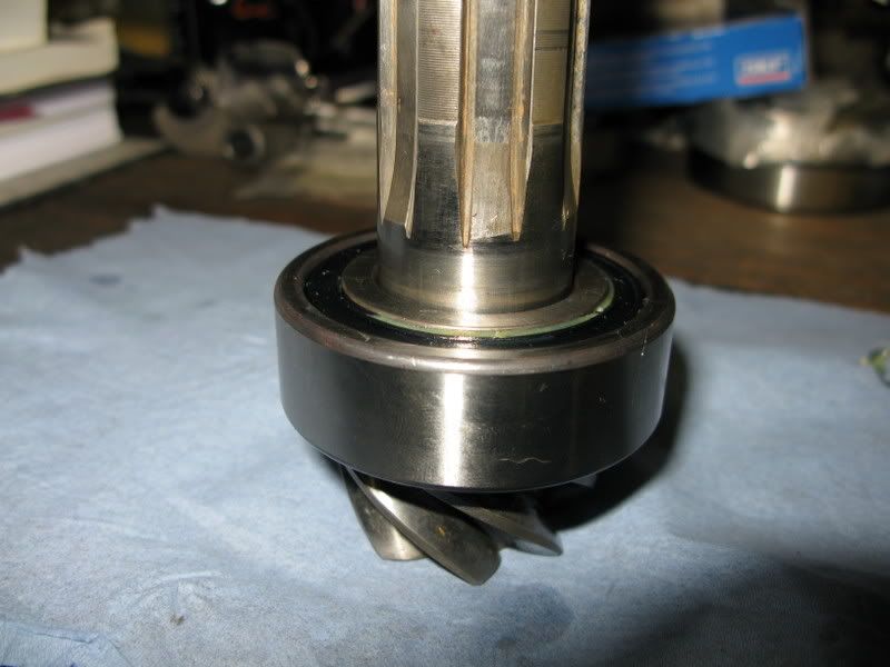
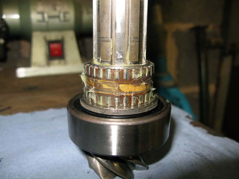
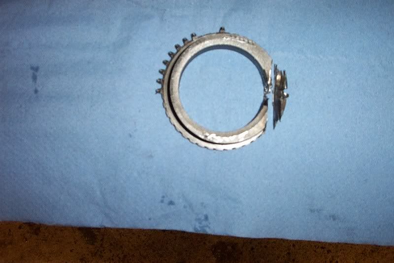
This is what second gear dog tooth ring looked like :shock: (luckily I managed to source a replacement from PRServices :) )

Image

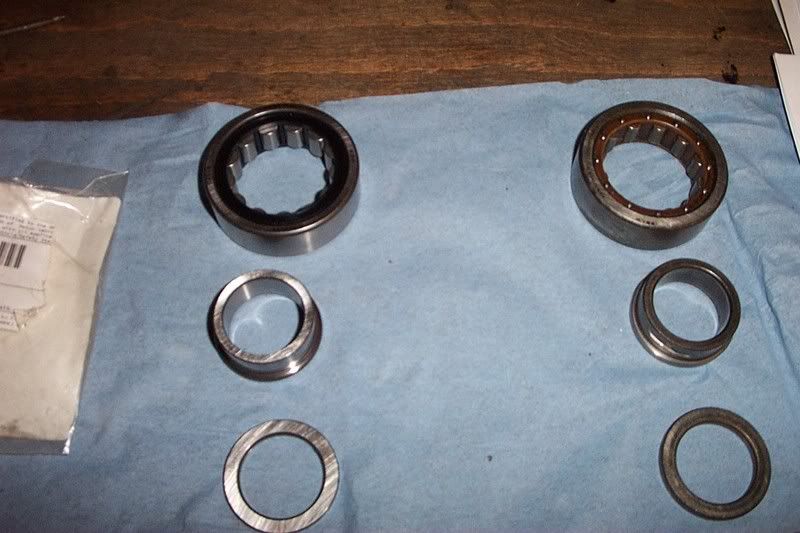
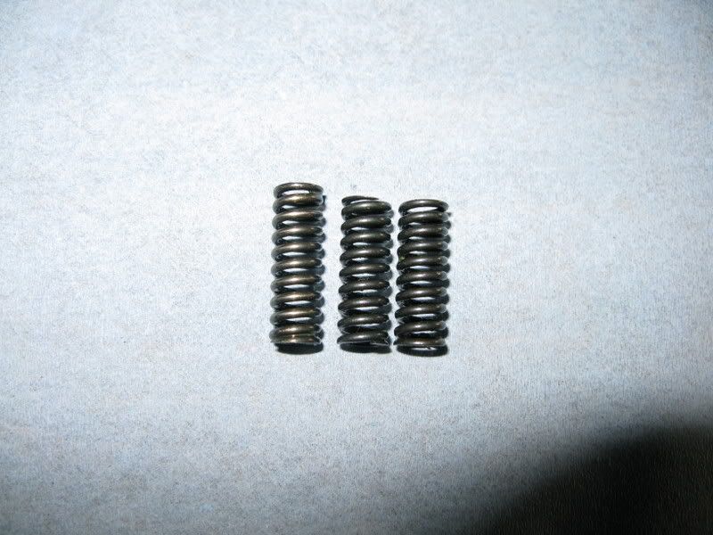
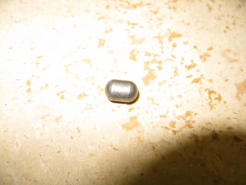
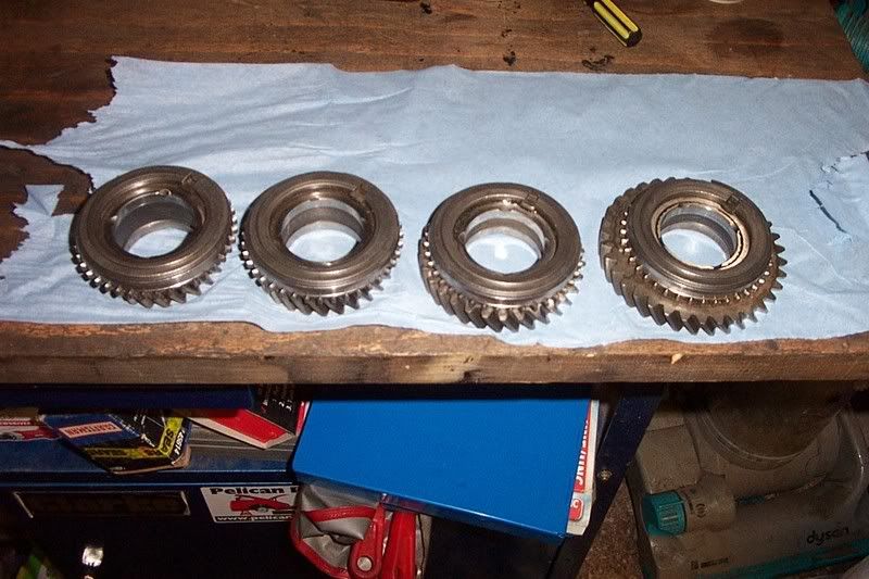
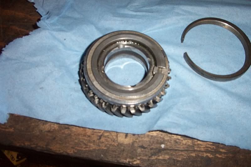
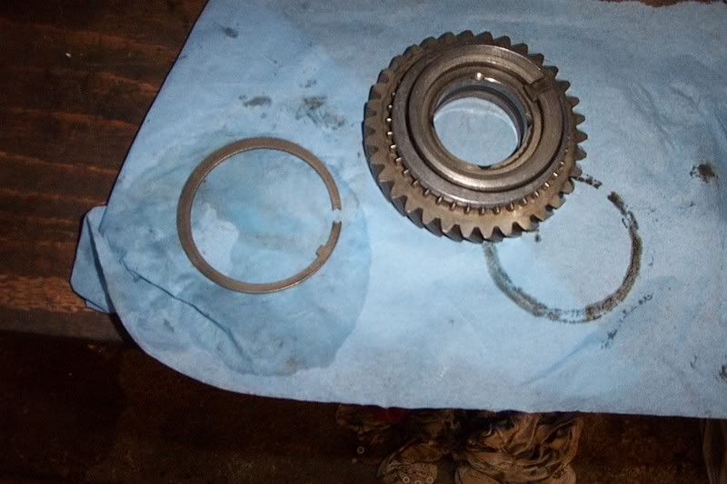
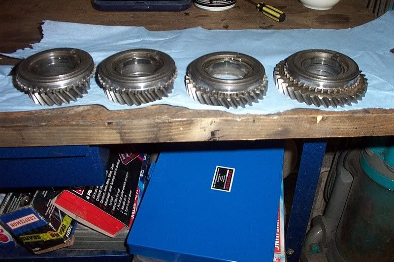
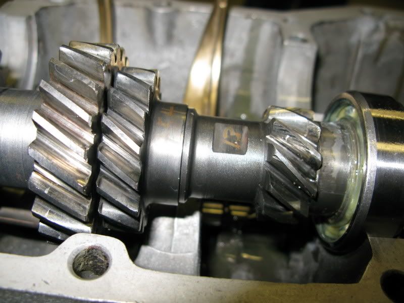
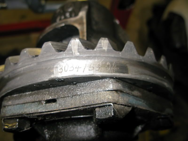
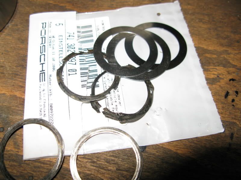
and this is what the spacer shims looked like

Image

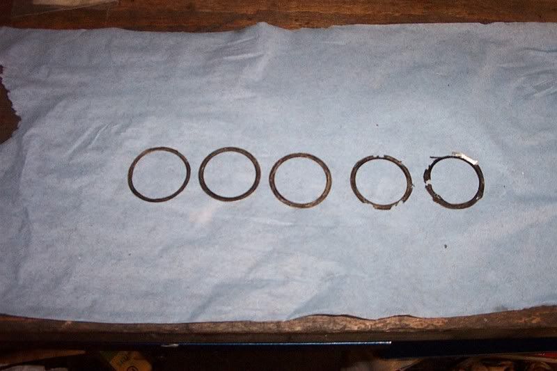
So no wonder it wasn’t working too well!
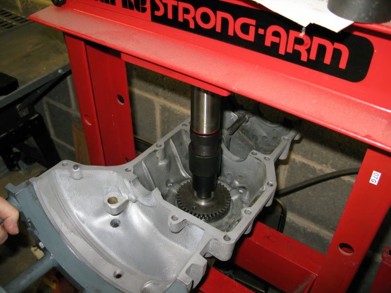
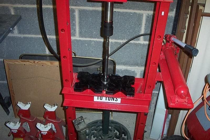
(Its worth saying here that you will need a hydraulic press to disassemble the pinion/main shafts – and when you do get ready to catch the roller needles!!!)
Last edited by 58A - 71E on Thu Feb 19, 2009 10:14 pm, edited 2 times in total.
James

'58 356A 1600n
'71 911E 2,2


#0335
58A - 71E
Put a fork in me, I'm done!
Posts: 1842
Joined: Tue Nov 28, 2006 1:49 pm
Location: Yorkshire

Post by 58A - 71E »

These are the cases stripped and separated

Image

Before attempting to work on the GB it helps if there’s some information to hand.
Thanks here go to Bill (Dakota) for recommending the Henry Elfrink book (which is invaluable I think to anyone working on a 356) and also to Mike Smith at PRServices, who photocopied the section on GBs from the Porsche workshop manual and faxed it to me, and very kindly gave up an hour of his time to talk to me on the phone. Porsche also kindly supply PET online now at their website.

This is the Elfrink book which I got from Roger Brays:

Image
James

'58 356A 1600n
'71 911E 2,2


#0335
58A - 71E
Put a fork in me, I'm done!
Posts: 1842
Joined: Tue Nov 28, 2006 1:49 pm
Location: Yorkshire

Post by 58A - 71E »

Next job was to get everything clean to reassemble.

I had the cases, intermediate plate and nose cone vapour blasted and some external components (axle tubes, cradle etc) powder coated. To make sure everything was as it should be I popped them in the house parts washer :wink:

Image

and went through with brake cleaner and a rifle brush to get into all the nooks and crannies and was able to finally see all the external stampings on the cases

Number 870 stamped on each case half

Image

Image

GB serial number stamped on bottom and next to starter motor

Image

Image
Last edited by 58A - 71E on Thu Feb 19, 2009 10:16 pm, edited 2 times in total.
James

'58 356A 1600n
'71 911E 2,2


#0335
58A - 71E
Put a fork in me, I'm done!
Posts: 1842
Joined: Tue Nov 28, 2006 1:49 pm
Location: Yorkshire

Post by 58A - 71E »

More numbers on the sides, including the VW stamps (the case was sourced from VW on these early GBs)

Image

Image

From reading the 356 register book I am pretty certain that 26 refers to February 1956, which would fit with the date cast into the diff carrier of 5 Jan 1956 seen here

Image

I was curious as to why the shims shown earlier had become damaged, upon examining the pinion shaft it would appear that the inner race of the forward bearing had spun, but fortunately has not grooved the pinion shaft

Image
James

'58 356A 1600n
'71 911E 2,2


#0335
58A - 71E
Put a fork in me, I'm done!
Posts: 1842
Joined: Tue Nov 28, 2006 1:49 pm
Location: Yorkshire

Post by 58A - 71E »

Given that I am not anticipating rebuilding this thing any time soon I thought probably best to replace all the bearings (there are 6 in total) with new ones in a belt and braces approach. Two of them I was able to source from my local OPC, the others came from Stoddard, luckily I bought these before the exchange rate took a dive.

Here’s that bearing along with the new one. Hopefully you can see that there are more rollers in the new one on the left

Image

Reading in the registry book it would appear that the supply of bearings over the years has not always been great, with some inferior types on the market with less balls/rollers, luckily these all appeared to have at least if not more than the same number as original.
Last edited by 58A - 71E on Thu Feb 19, 2009 10:18 pm, edited 1 time in total.
James

'58 356A 1600n
'71 911E 2,2


#0335
58A - 71E
Put a fork in me, I'm done!
Posts: 1842
Joined: Tue Nov 28, 2006 1:49 pm
Location: Yorkshire

Post by 58A - 71E »

I mounted the case halves individually onto my stand (this is one I originally purchased for my 911 engine rebuild, luckily it has exactly the same size holes for the 356 engine and GB too 8) ) and cleaned the sealing surfaces, here is the left side which is used to build up on

Image

Image

The first things to be put in were the diff bearings. There are two different sorts, a 7210 and a 6210 (stamped on the bearing).

These are an angular contact bearing and a deep grove bearing. The angular contact is fitted into the left case half, and the deep groove into the right. Here you can see the old style next to the new one, the new one appears to have a plastic/nylon construction inside as opposed to the old metal one.

Image

Image
Last edited by 58A - 71E on Thu Feb 19, 2009 10:19 pm, edited 1 time in total.
James

'58 356A 1600n
'71 911E 2,2


#0335
58A - 71E
Put a fork in me, I'm done!
Posts: 1842
Joined: Tue Nov 28, 2006 1:49 pm
Location: Yorkshire

Post by 58A - 71E »

It wouldn’t go in with a gentle tap, so I used my hydraulic press with reverse gear as a handy boss to push it in – it really doesn’t take much pressure – TBH I only used the press as I wanted to be sure it seated squarely with the bevel in the case half

Image

Next is to insert the springs and detent balls for the shift levers. The springs are different in size, the reverse lever spring is longer than 1&2 and 3&4

Image

These are placed in the case half (not in the intermediate plate as per the later GBs) and the balls sit on top

Image

Reverse lever is the lowest (to the right of the pic) and is shown here inserted with the spring and ball in place.

Image

The detent locks go in next i.e. these things

Image

There are 2 of them, they are well fiddly to put in the end of the case half, with some circlip pliers, in the 2 holes between reverse and 1&2 and then between 1&2 and 3&4

Image

Image
James

'58 356A 1600n
'71 911E 2,2


#0335
58A - 71E
Put a fork in me, I'm done!
Posts: 1842
Joined: Tue Nov 28, 2006 1:49 pm
Location: Yorkshire

Post by 58A - 71E »

Then the shift levers can go in

1&2 after reverse (fork not installed in this pic yet)

Image

then 3&4 with shift forks placed in loosely at this stage

Image

Here you can see the inspection holes to tighten the bolts up once everything is ready to tighten up once all relevant measurements have been taken

Image

The bolts don’t line up until the shift rods are moved into alignment with the holes
James

'58 356A 1600n
'71 911E 2,2


#0335
58A - 71E
Put a fork in me, I'm done!
Posts: 1842
Joined: Tue Nov 28, 2006 1:49 pm
Location: Yorkshire

Post by 58A - 71E »

Then the assembly of the shafts can begin. Here’s a photo of the assembly taken from the Elfrink book (all images posted for educational purposes only)

Image

I started by assembling the new synchro rings onto the speed gears

Image

Image

Image

Image

Image

Image

Image

Image

Again I managed to get these from Stoddard before the exchange rate went south. They are quite easy to change, they are only held in with a large circlip; and they seat in the slot behind the dogtooth ring. Hopefully the photos show the subtle differences between the new and old rings, the new ones have a distinct bevel edge to them, the old ones have worn down smooth.
Last edited by 58A - 71E on Thu Feb 19, 2009 10:29 pm, edited 2 times in total.
James

'58 356A 1600n
'71 911E 2,2


#0335
58A - 71E
Put a fork in me, I'm done!
Posts: 1842
Joined: Tue Nov 28, 2006 1:49 pm
Location: Yorkshire

Post by 58A - 71E »

Here’s all 4 new ones assembled

Image

I then replaced the two bearings on the main shaft, fortunately these are easy to do with only circlips to fiddle with, and there was no damage evident to any of the gears. This was again done in the press.

Image

reverse gear put on and then the nut was torqued up to 18lbft on the end

Image

a new oil seal slid on (slightly different to the old one which was bevelled to sit in the cases) and then placed in the case half out of the way so it didn’t get full of crap on the floor

Image
James

'58 356A 1600n
'71 911E 2,2


#0335
58A - 71E
Put a fork in me, I'm done!
Posts: 1842
Joined: Tue Nov 28, 2006 1:49 pm
Location: Yorkshire

Post by 58A - 71E »

I then noticed some markings on 3rd and 4th gears

Image

Image

The 3B and 4C I recognised from this info I found on 356 enterprises website

Image

However, there were no markings on 1st or 2nd so I decided to count up the individual teeth on each gear pair

Image

I ended up with

11/34 = 1B

17/30 = 2B

23/26 = 3B

27/22 = 4C

i.e. BBBC, which appears to be quite a common set up
James

'58 356A 1600n
'71 911E 2,2


#0335
58A - 71E
Put a fork in me, I'm done!
Posts: 1842
Joined: Tue Nov 28, 2006 1:49 pm
Location: Yorkshire

Post by 58A - 71E »

Next was to check the crown and pinion

These are matched as pairs at the factory and shouldn’t be split up, if one needs changing then both need changing

Here’s the end of the pinion, which shows number 3034 etched into it

Image

And the crown, which also shows number 3034 etched into it

Image

So luckily a matching pair; there are other markings on here which we’ll come on to later. (note it says 59.04 on the crown which is the R value and 0.15 on the pinion which is the backlash)
I also then counted the teeth on these two, which were

7: 31

This appears to be the common set up, although others were available e.g. 7:34 etc
James

'58 356A 1600n
'71 911E 2,2


#0335
58A - 71E
Put a fork in me, I'm done!
Posts: 1842
Joined: Tue Nov 28, 2006 1:49 pm
Location: Yorkshire

Post by 58A - 71E »

Then onto the pinion shaft assembly

First (on this type of GB) is the shims

PET shows early shims available in 0.05mm increments,

Image

Unfortunately none of these are available from OPC, instead only 0.3mm later 741 are available, so those are what I ordered, having to reuse the best ones I had available. The preliminary determination of how many to use is based upon the R value shown on either the crown or pinion. It is based on a nominal value of 59.80mm. (not to be confused with post 1962 GBs where the nominal R value changes to 59.22mm). Therefore my pinion needs to be 59.80-59.04 i.e. spaced 0.76mm. Here’s the pic from the manual showing what measurement this is

Image

And in Elfrink

Image
James

'58 356A 1600n
'71 911E 2,2


#0335
58A - 71E
Put a fork in me, I'm done!
Posts: 1842
Joined: Tue Nov 28, 2006 1:49 pm
Location: Yorkshire

Post by 58A - 71E »

It would have been easier to simply replace the same number and size as what came out of there, but given that my old shims were knackered I couldn’t do that. I measured as best I could what I originally had and guessed it to be 1.05mm. Therefore I knew I would probably be about 0.3mm different from original – but that doesn’t matter as a final adjustment is made later with shims next to fourth gear. Here’s the first shims going on.

Image

Image

Then the bearing with the flange toward the pinion

Image

Then a thrust washer and the roller bearing inner race


Then the cage with rollers – I used a generous helping of grease to stop them falling out of the cage, instead of the special holding tool, which I didn’t have.

Image
Last edited by 58A - 71E on Thu Feb 19, 2009 10:34 pm, edited 1 time in total.
James

'58 356A 1600n
'71 911E 2,2


#0335
Post Reply