

just welding up engine bay on a 356 as origional had been mullered around a lot.
hopefully I have structure right on sides now but i am now in a position to put in engine trays and heat shield.
i have made up a rear piece as well.
Originals of these were plated top and bottom and they had almost rotted right out as had bottoms of side walls.
pics here as i can seem to put them up on here
http://www.volkszone.com/VZi/showthread.php?t=288026
I need measurement down the side triangle at front of engine bay down to engine tray and also the engine tray comes in two halves but these overlap. Is this right i though they were supposed to butt together and then use the joining strip provided.
if anyone can help me i would be most grateful as its holding up my workshop and i have two bugs of mine which I need to get through test in next couple of days so I can tax them and store on road as I have nowhere else to put them
If anyone could call me on my mobile with info I would be eternally grateful..
07773203551 and i will owe you big time
Cheers
Restoration work on a 356b
Moderator: Bootsy
-
hashman

- DDK forever
- Posts: 708
- Joined: Thu Dec 11, 2003 12:46 am
- Location: Midlands
Try this link, he's restored his car and documented lots.
Hope it helps.
http://www.project356.com/356/Images/En ... ed%201.jpg
http://www.project356.com/restoration_by_date.htm
Hope it helps.
http://www.project356.com/356/Images/En ... ed%201.jpg
http://www.project356.com/restoration_by_date.htm
Keep the Outlaw Faith
-
Rustbucket
- DDK forever
- Posts: 581
- Joined: Mon Jan 26, 2004 1:15 pm
- Location: Hove , Brighton
- Contact:
sadly my 356 is too far away to do quick measurements.
From memory what you posted on vzi looks right?
if you have two halves bought as new panels I would expect they are oversized to allow for differences when joining with an existing panel.............so just cut them to size as you remember.
the 90degree lip for the tray perimeter at the bottom fits inside the engine bay, (so you can see it), again from memory.
dan
Contact me if you have any 356b coupe parts !!!!
-
Nic B-C
- DDK above all
- Posts: 153
- Joined: Sat Jan 14, 2006 1:32 pm
Thanks very much for those pics its sort of as I thought then.
Luckily a guy local to me has one so Im gonna pop over to see his tommorrow.
Its great when a plan starts to come together. im always very nervous about doing something for the first time especially on an expensive car and even more so when its someone elsess
Cheers
Luckily a guy local to me has one so Im gonna pop over to see his tommorrow.
Its great when a plan starts to come together. im always very nervous about doing something for the first time especially on an expensive car and even more so when its someone elsess
Cheers
-
Nic B-C
- DDK above all
- Posts: 153
- Joined: Sat Jan 14, 2006 1:32 pm
Had a good lok now and I see what needs to go where I tink. I need to put the engine trays a lot higher and link seam up to end of the v section sides plates and top of rear rail. I then piut the bottom of heat shield on bottom of the rear rail and to the front section of the engine tray.
However I do note from the pics not of this car
http://www.project356.com/356/Images/Ne ... ld%202.jpg
that the tray is bulge side up yet on another car i have seen this the other way up, can anyone confirmthis either way please
However I do note from the pics not of this car
http://www.project356.com/356/Images/Ne ... ld%202.jpg
that the tray is bulge side up yet on another car i have seen this the other way up, can anyone confirmthis either way please
-
Nic B-C
- DDK above all
- Posts: 153
- Joined: Sat Jan 14, 2006 1:32 pm
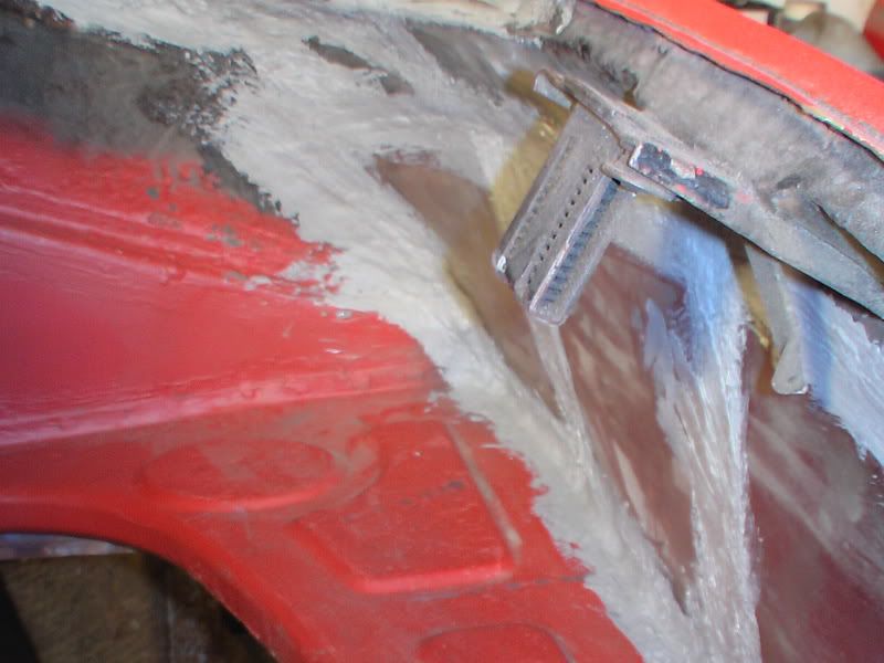
Ive also noticed from this pic the small support bracket, presumably this is one of the ones mentioned in the Stoddard catalogue but has no pics of it.
If anyone has any pics of these hanging around and could post I would be really grateful, same applies need fixing position. This must just stabilise the rear panel like the v frames behind the middle of the triangular sections on the side.
I left both those with small tabs of clean metal on to get spacingings right and to make them easy to weld.
Also the piece from lock down should this be a flat or curved panel as this had a massive bad repair on this car. looks as though it should be straight down from link above.
-
Rustbucket
- DDK forever
- Posts: 581
- Joined: Mon Jan 26, 2004 1:15 pm
- Location: Hove , Brighton
- Contact:
-
Nic B-C
- DDK above all
- Posts: 153
- Joined: Sat Jan 14, 2006 1:32 pm
-
Nic B-C
- DDK above all
- Posts: 153
- Joined: Sat Jan 14, 2006 1:32 pm
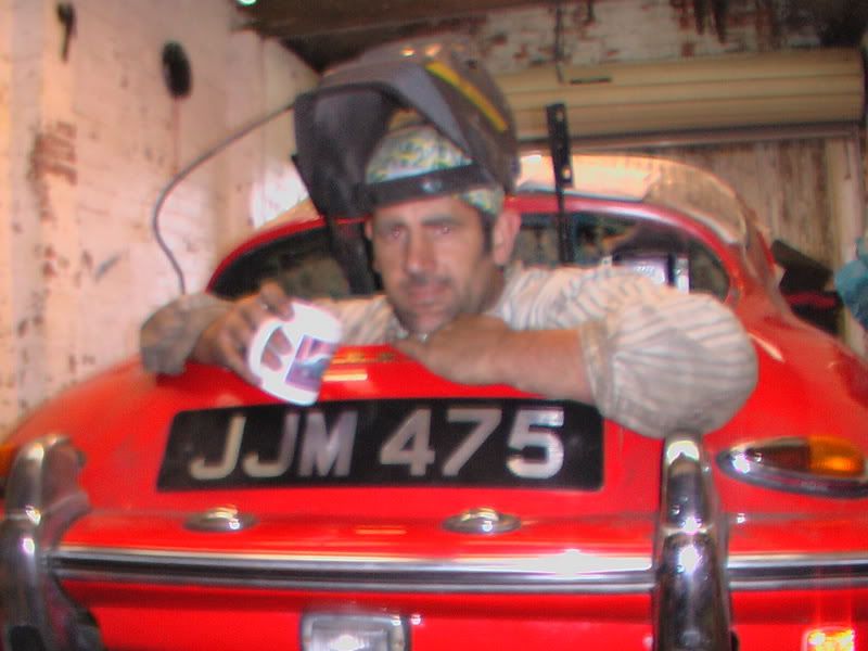
Not mine but a guy called Kevin from Washington.
Been working on it on and off for a while now.
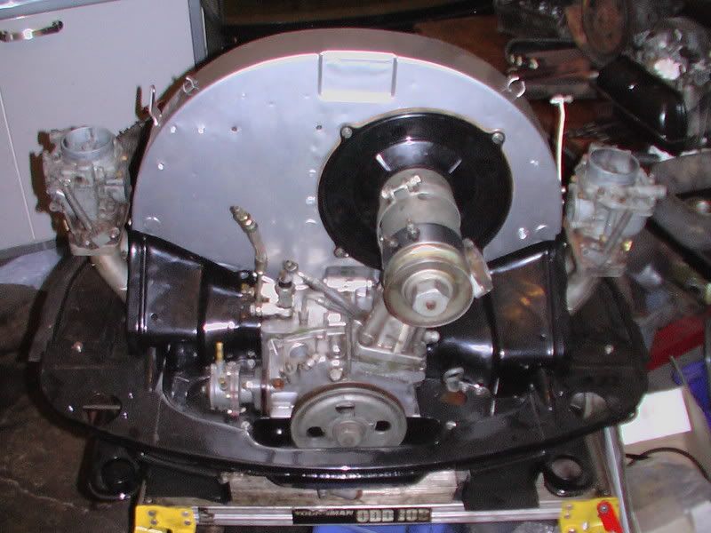
Had the engine out and refurbished everything including carb rebuilds and fuel pump rebuild, and full tinware powdercoating.
Just rebuilt all the engine bay area started buying the panels but got hit with a massive bill so made the rest.
Still got the gearbox to remove and sort the seals out.
Once its all running for the summer gonna then start on bodywork
Been working on it on and off for a while now.
Had the engine out and refurbished everything including carb rebuilds and fuel pump rebuild, and full tinware powdercoating.
Just rebuilt all the engine bay area started buying the panels but got hit with a massive bill so made the rest.
Still got the gearbox to remove and sort the seals out.
Once its all running for the summer gonna then start on bodywork
-
Nic B-C
- DDK above all
- Posts: 153
- Joined: Sat Jan 14, 2006 1:32 pm
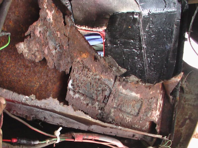
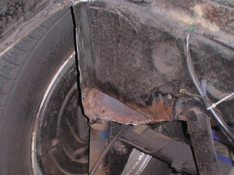
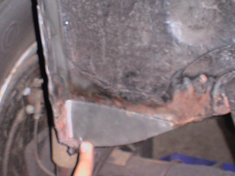
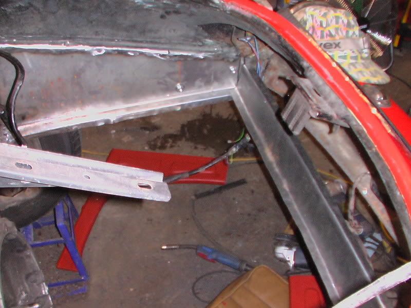
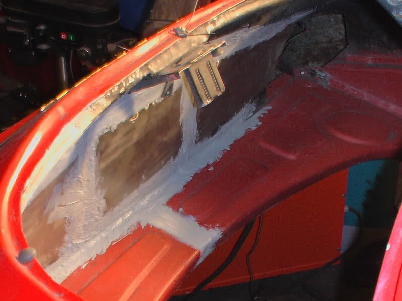
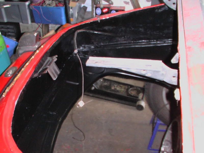
Here I have cut out the engine tray but discovered more rot going up the side diagonal piece so made the decision to take these out on both sides of the bay.
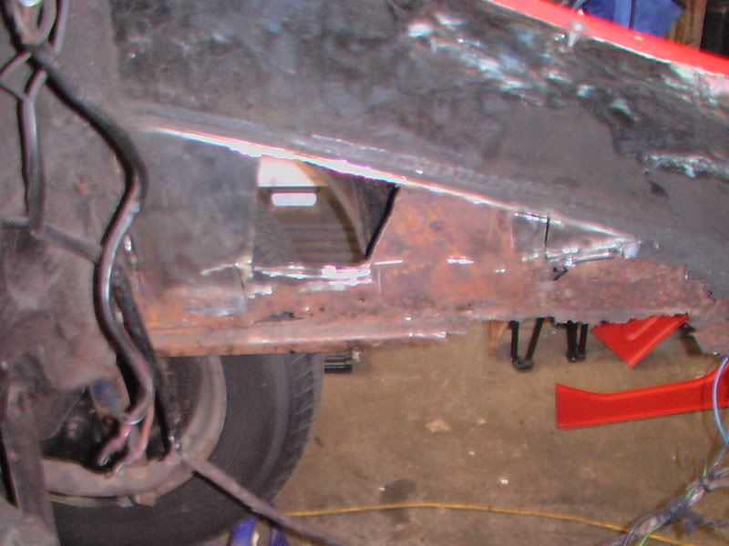
here i am caefully cutting away the side as I was not sure at this stage wether it should be single skin or double skin here and wanted to make sure of construction as i have never worked on one of these great cars before. did lots of internet searches and mailed a lot of owners and even went over to see maddison but his being slightly earlier has a different configuration here as well.
Here you can see I have part cut away the back wall showing the old support rail. You will note the curved line at top which is actually the crap repair panel which had been slapped over the rot previously causing yet more damage. I will take this out later.
-
Nic B-C
- DDK above all
- Posts: 153
- Joined: Sat Jan 14, 2006 1:32 pm
Here you can see I have cut it up to full height now and will clean it all back for welding up later.
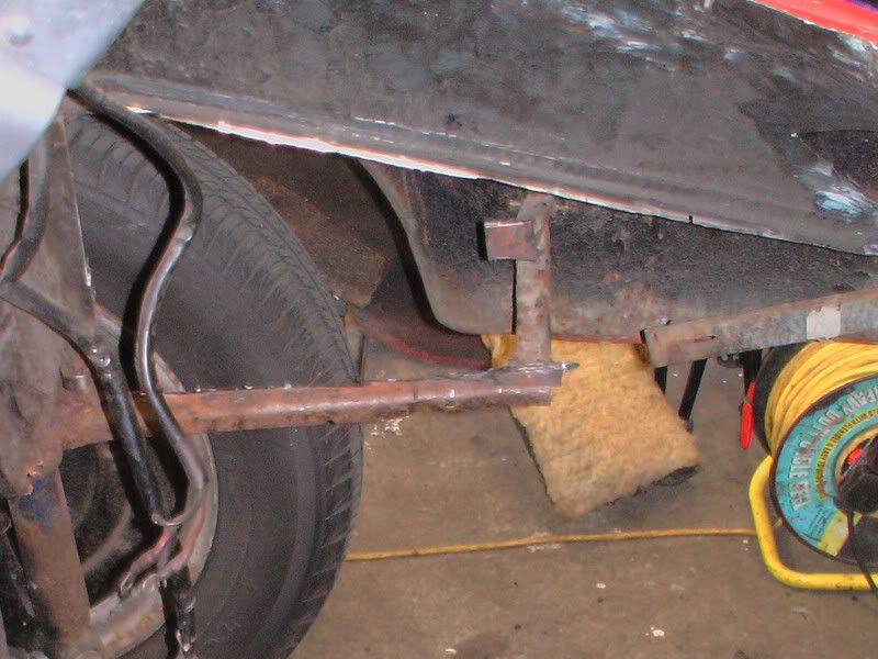
Cut side out now but left bottom rail in for further measurement and fitting up. Note the rear wing mounts still in place. I will be reusing thse for now until bodywork is done at a later date to preserve paintjob.
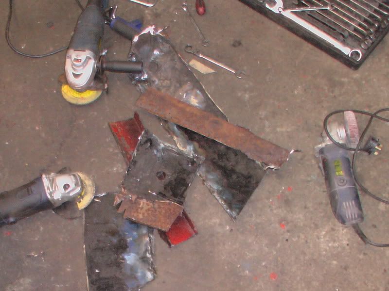
Note how I use several cheap 4-5 " grinders with different heads on which saves a lot of messing about. here i think I have a flap wheel, a plasma thin disc and a horizontal flap disc.
Next sorted out bases of firewall which are box construction
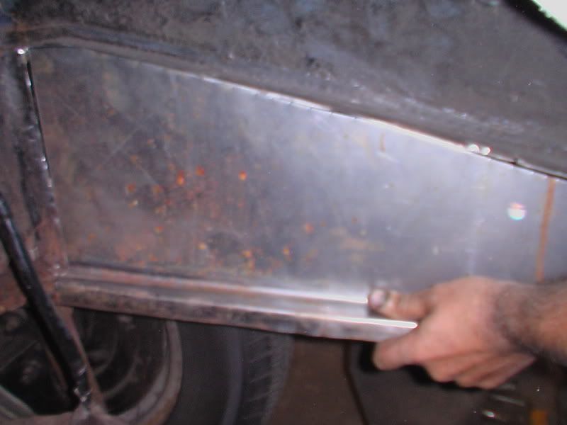
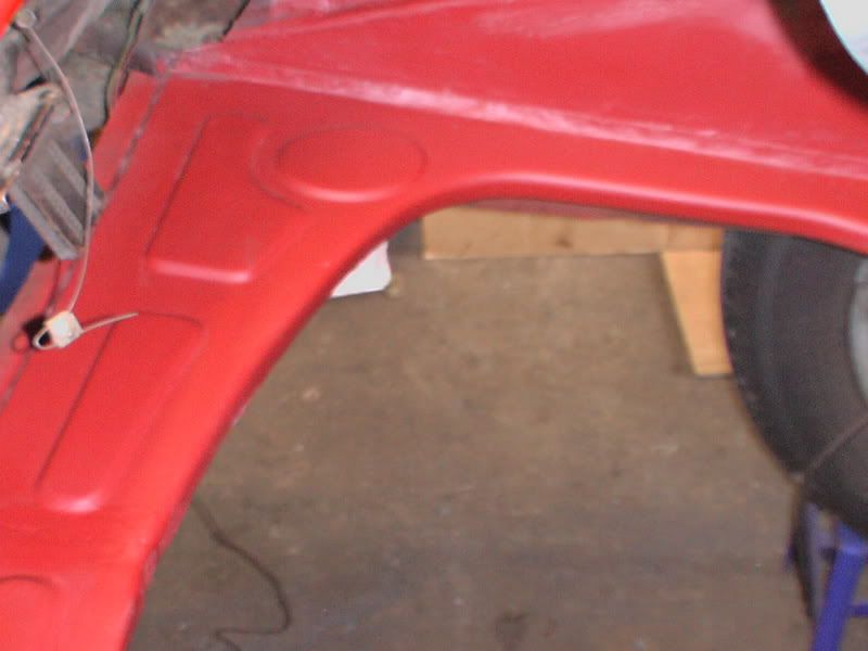
Then came the replacement side plates, note the lips on the bottom which is for the B models which this is. The a models like maddisons dont have this shaping and are more primative.
-
Nic B-C
- DDK above all
- Posts: 153
- Joined: Sat Jan 14, 2006 1:32 pm
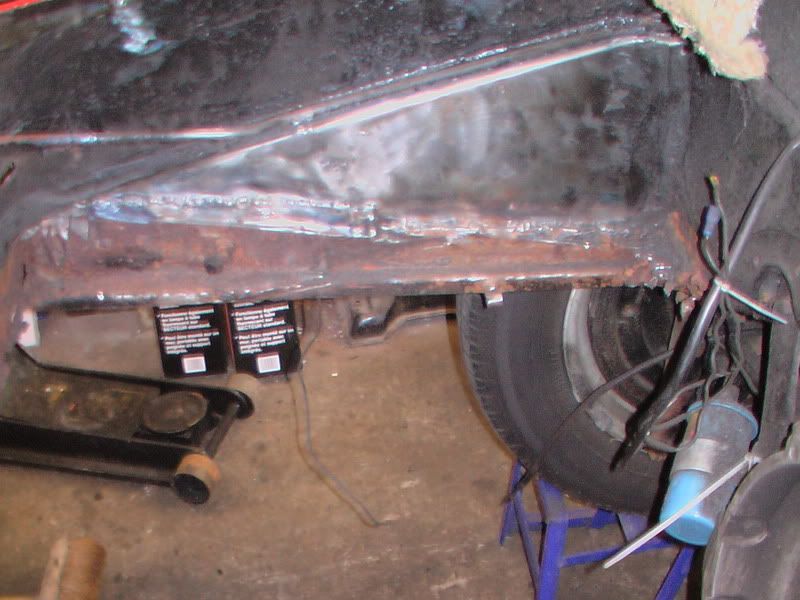
Welded in and mostly ground down side
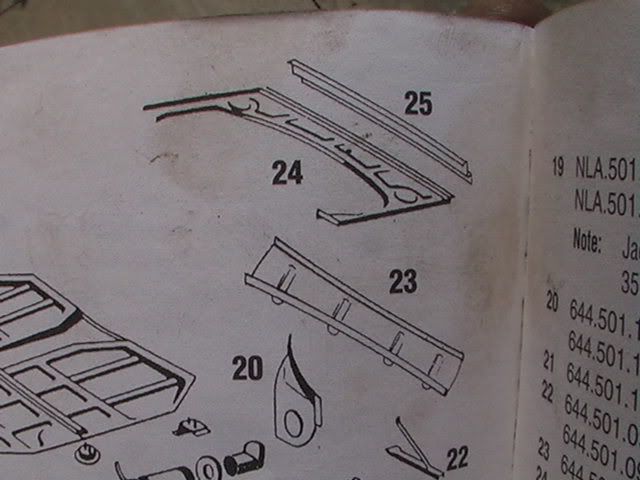
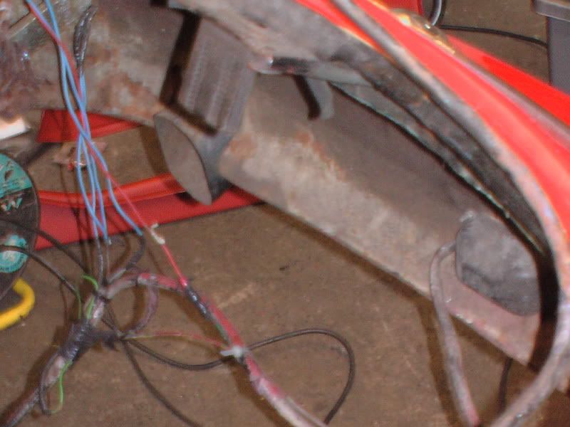
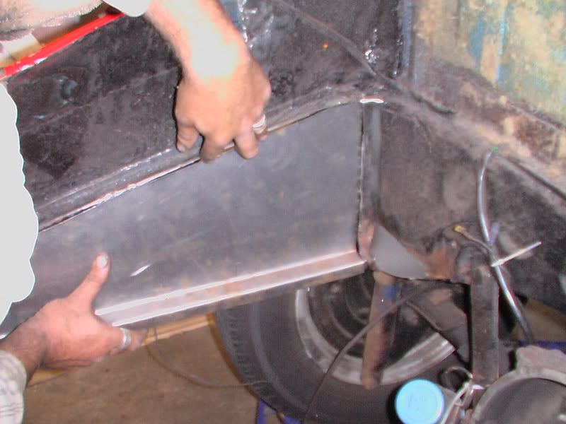
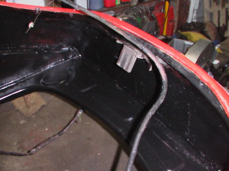
next made up the back support bar which holds the engine surround tray as show in diagram at top. This is a double bend bracket and the warpage over the entire length on straight bending was amazing so took some working. Was too big for my folder so the back bars from the T25 pickup provided the most excellent former.
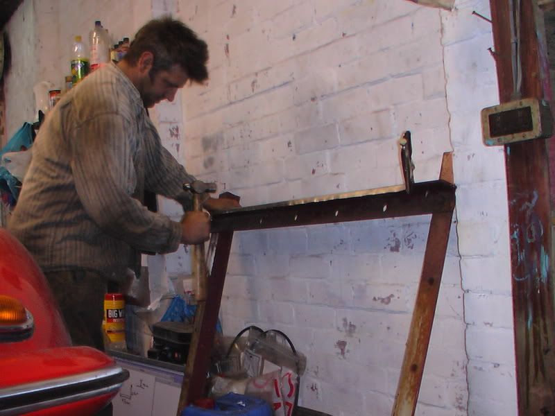
here you can see it test fitted but I made a boo boo at this stage and didnt bolt the bumper brackets through so cut the damn thing too short and had to remake it.
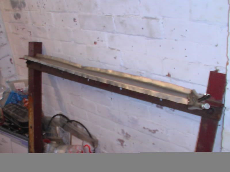
You can see the bracket bolts ona diagonal here and these help locate the engine side trays.
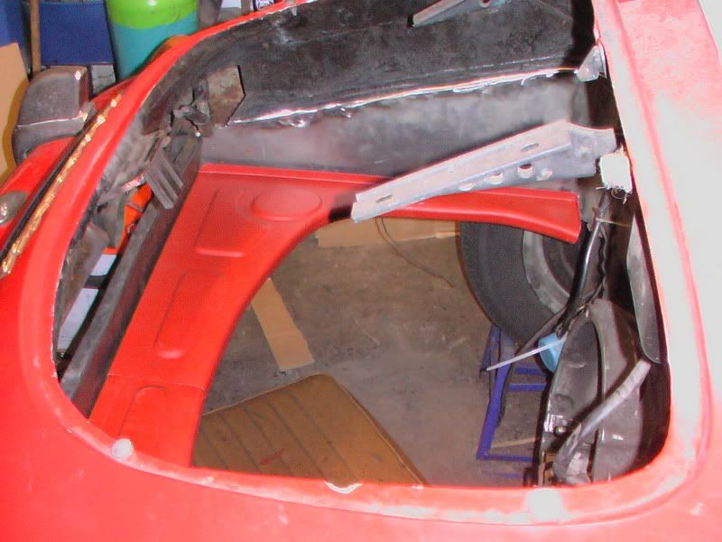
Ive test located the tray here just for size as it actually sits up higher
here you can see how the tray comes supplied in two halves which overlap so it had to be all test fitted in place before cutting and then welding in correct position.
next made up the back support bar which holds the engine surround tray as show in diagram at top. This is a double bend bracket and the warpage over the entire length on straight bending was amazing so took some working. Was too big for my folder so the back bars from the T25 pickup provided the most excellent former.
here you can see it test fitted but I made a boo boo at this stage and didnt bolt the bumper brackets through so cut the damn thing too short and had to remake it.
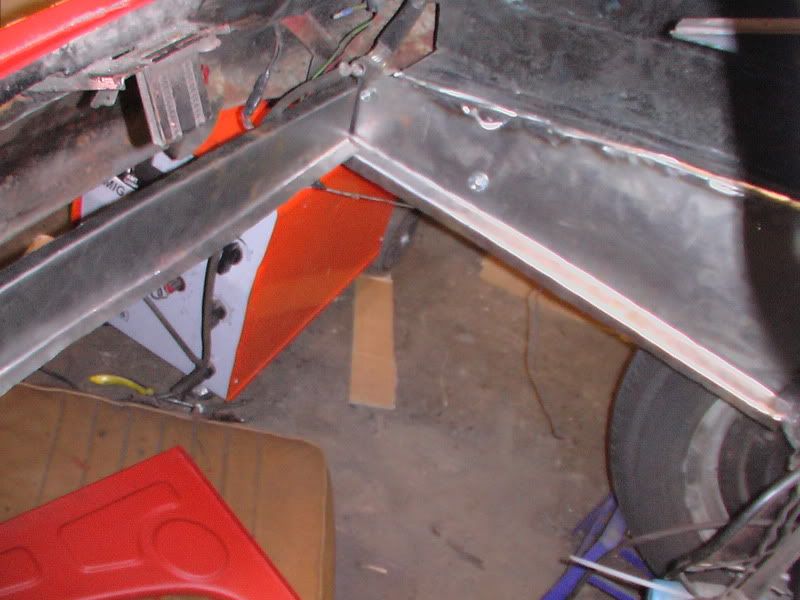
You can see the bracket bolts ona diagonal here and these help locate the engine side trays.
Ive test located the tray here just for size as it actually sits up higher
here you can see how the tray comes supplied in two halves which overlap so it had to be all test fitted in place before cutting and then welding in correct position.
-
Nic B-C
- DDK above all
- Posts: 153
- Joined: Sat Jan 14, 2006 1:32 pm
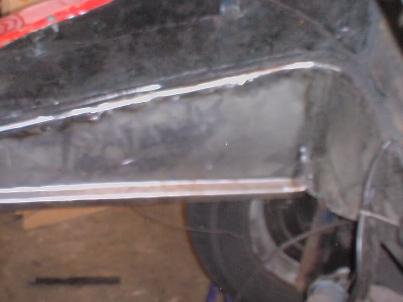
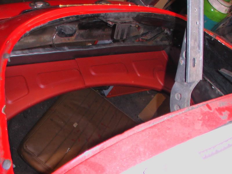
The upper trays actually sit on the top of that support bracket and then the curved lower heat shield goes from front lip to the bottom bend in the bar. See top diagram again.
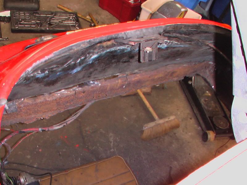
Here i had to make up back wall in 5 pieces merely due to space and shape. As you can see each seam has bean seam welded.
The corners were a bit of a pain though.
Finished it all off with a couple of layers of bonda primer and a good gloss black paint. the tube you can see there is the decklid release cable guide tube. this will be located in later