Page 3 of 5
Posted: Tue Oct 30, 2007 6:52 pm
by Barry
Brilliant thread, John! Great reading and excellent pics

.
Posted: Tue Oct 30, 2007 7:26 pm
by johnM
Built the heads up today.
I lapped the valves into the heads
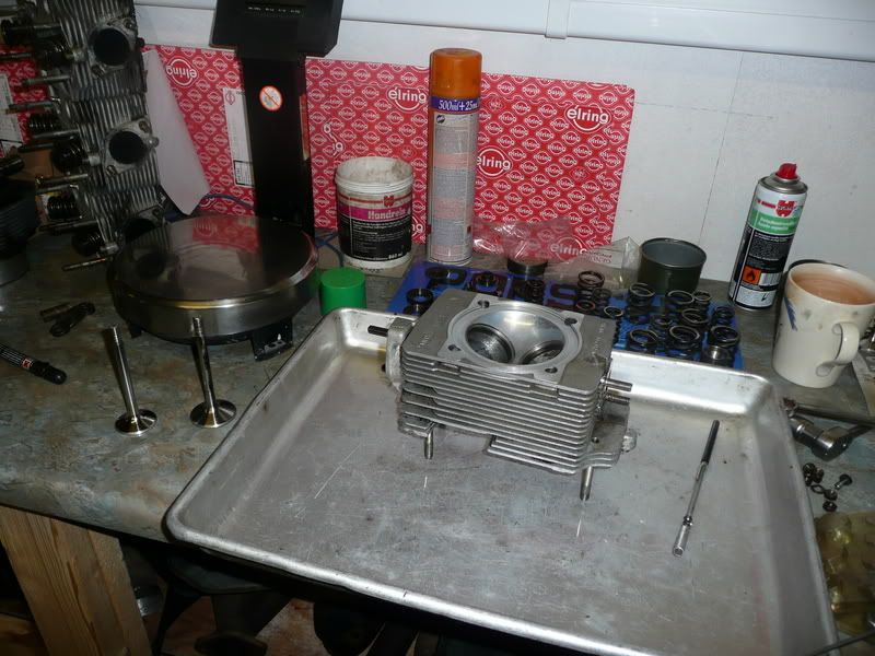
After washing off all of the grinding paste off, I then went about shimming up the valves, it is important that the base of the spring seat is shimmed correctly with referance the the spec book, in my case the inlets needed to be shimmed to 35.5mm and the exhaust to 34.5 mm. I used a porsche tool for this. If the heads are not shimmed correctly the spring can become coil bound before the cam has pushed the valve fully open, this can ruin the cam lobe as so much force is needed to compress the spring, if too loose the sping will not have enough pre load and could cause valve float at high rpm.
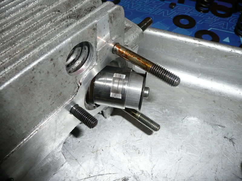
A head all shimmed and ready to be installed. The outer spring is progressive and needs to be installed the right way round with the tighter coils at the base.
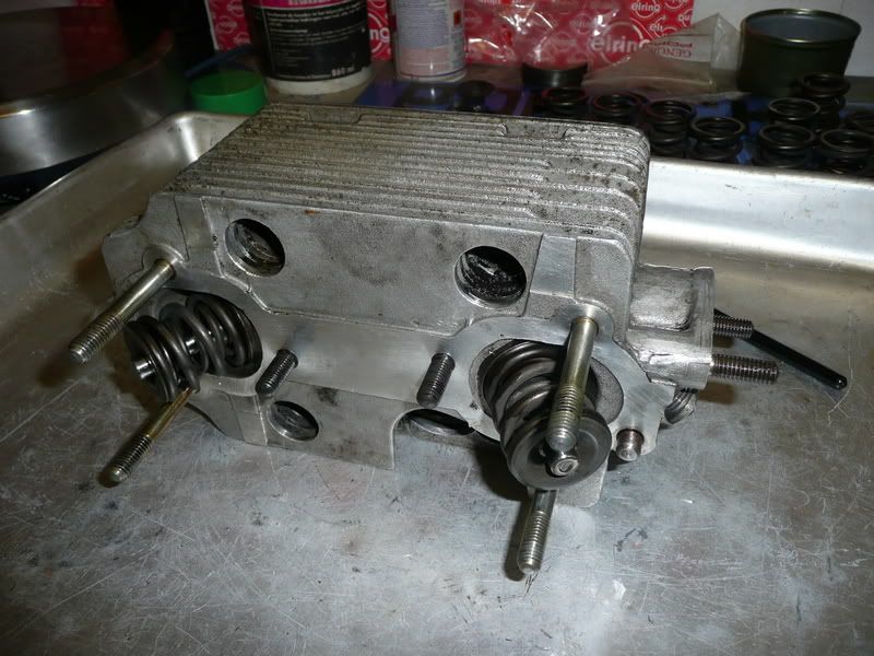
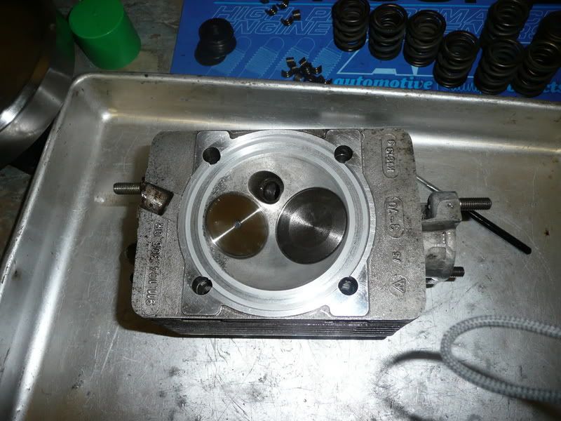
A couple of heads installed onto the crankcases.
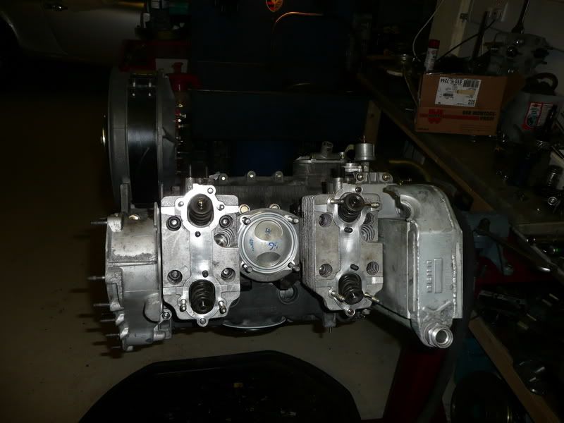
well thats it for now.
Kind Regards
Posted: Tue Oct 30, 2007 8:26 pm
by 58A - 71E
Really enjoying this John, glad you are sharing it with us.
Are the new pistons E or S? Are you keeping the E cam? Any other mods planned?
Posted: Tue Oct 30, 2007 10:14 pm
by johnM
The pistons are S but the E cams will be going back in for the time being, going to S cams will mean that the MFI pump will need to be recalibrated and the distributor will need its advance curve modified, this could be done easily in the future if the kids haven’t starved, fortunately they like bread and jam. Although it will never deliver power like a S cam it is rumoured that E cams can produce as much power, I suppose we will see.
Regards
Posted: Wed Oct 31, 2007 9:17 am
by Dyno Soar
I have fond memories of that tool...

Cool thread..

I must get my car down to Bob's too for a dyno run.
Posted: Fri Nov 02, 2007 1:55 pm
by johnM
Manged to get all the heads on to day,
First you run the head bolts up but do not tighten once all three heads are on you carefully put on the cam carrier this has locating holes to mate up with pegs in the heads thus ensuring that the heads are located correctly before you tighten them up. The cam carrier is on only to locate the heads and will be removed after the heads are tight so they can be put on later.
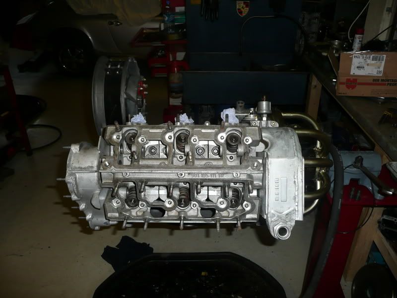
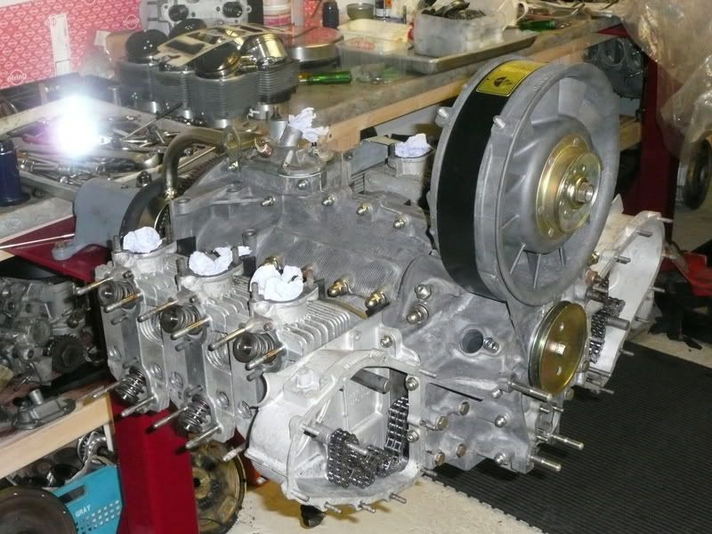
Once the cam carrier is on you can torque up the head nuts, start from the centre head and work out. once torqued then leave for a few minuets and then go and recheck, it is important that you use the correct type of torque wrench for this operation, a click type wrench is no good, this is because as you are tightening the nut the stud will be stretching, a click torque wrench will achieve its required torque and the stud will still be stretching, thus the final torque is less than you require, to go back and re-torque means overcoming stick shun between the nut and its washer. With a torque wrench that has no ratchet just a needle gauge you can apply the correct torque and see the bolt stretch, the needle will back off so you can keep the correct torque on the head nut until the stretch has stopped. Your head nuts will then be correct and will not require re-torquing again.
Posted: Fri Nov 02, 2007 2:42 pm
by 210bhp
John
Great thread. Keep it coming.
Cam timing soon.................love that job
Regards
Mike
Posted: Fri Nov 02, 2007 2:54 pm
by impmad2000
Ooo ! Excellent refresher course
I remember most of this from the top end rebuild course.
Most !! Not all !!
Cheers

Tim
Posted: Wed Nov 07, 2007 8:15 pm
by johnM
tossed a few more bits at the engine in the last few days,
we cleaned the heads and the towers and fitted them to the heads. Once that was done we put in the cams to ensure that they rotated freely. thankfully they did. The cam sproketand gear whent in and then it was time for the cam timing. Unfortunatly I forgot my camera but basicly you fit number 1 inlet and exhaust rocker gear and then adjust the tappets to 0.1mm you then rotate the crankshaft throught 2 full turns and measure how much the sping compresses, at top dead center, in my case it needs to be between 3mm and 3.3mm. to adjust this you move the cam sprocket in relation to the cam.
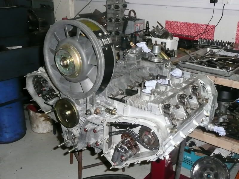
Make sure the cam sprockets go on the correct way, the one on the left has a deep dish to the front the one on the right has its dish to the back.
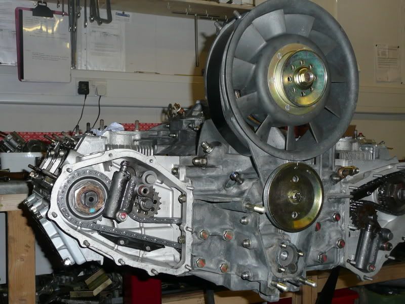
The MFI pump went on next along with some tin work.
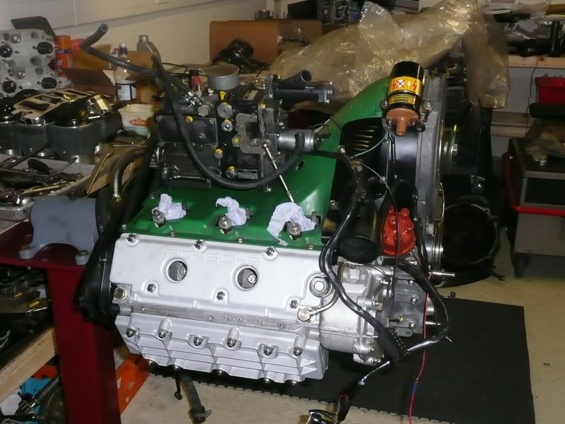
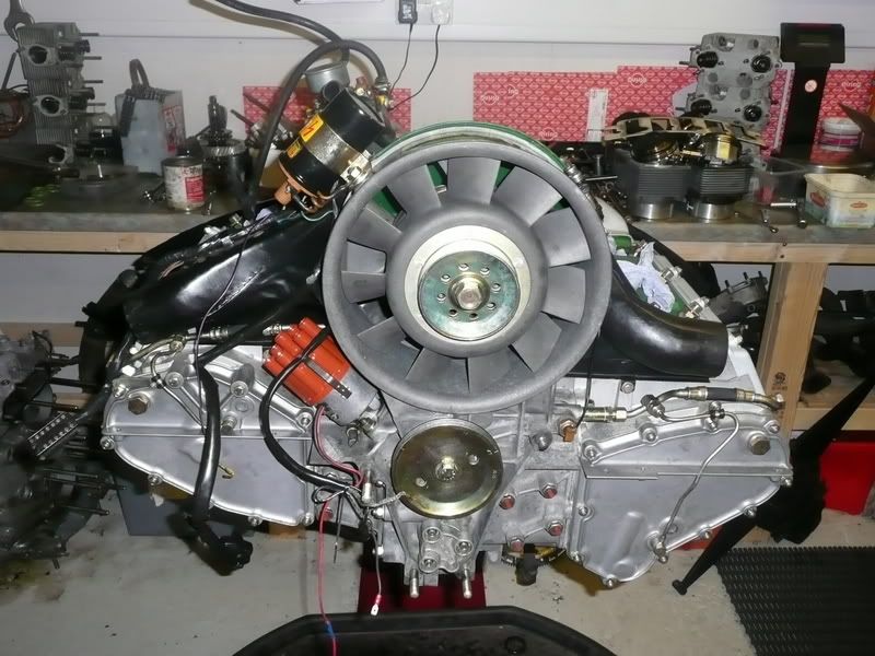
Then i put the exhaust and SSI on
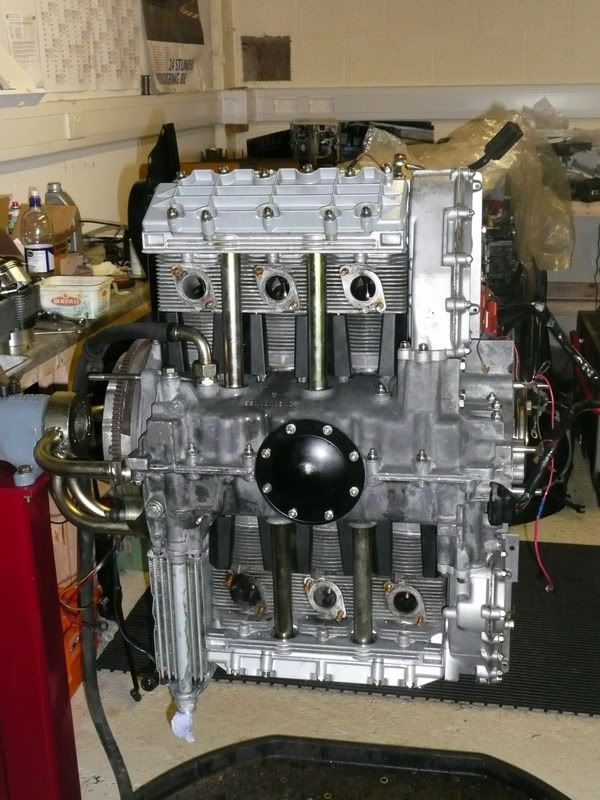
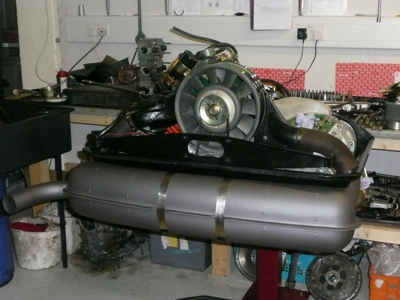
Not much more to do now

Posted: Wed Nov 07, 2007 9:32 pm
by impmad2000
John,
Was the choice of oil fed tensioners based on what was on the engine before ? or something else.
Looks good
Tim
Posted: Thu Nov 08, 2007 8:34 am
by Ian Donkin
Nice work John - has your exhaust been ceramic coated, or is that just a special paint finish?
I can imagine you'll be looking forward to getting this back on the road just in time for the gritting season

Posted: Thu Nov 08, 2007 12:23 pm
by Dyno Soar
Nice John.. real nice.
Posted: Thu Nov 08, 2007 7:40 pm
by johnM
Thanks guys, a little bit excited now.
John,
Was the choice of oil fed tensioners based on what was on the engine before ? or something else.
Tim the chain tensioners were already on the engine so thats why they went back on.
Nice work John - has your exhaust been ceramic coated, or is that just a special paint finish?
Ian the special coating is high temp paint out of a tin that was sprayed on. It looks nice at the mo but will proberbly drop off like most other paints, I will have to see.
Put some more bits together today.
Posted: Thu Nov 08, 2007 8:47 pm
by johnM
The first 2 photos are for Charlotte, you are probably missing yours

.
We bolted on the gearbox and located the release arm to the bearing, on the 911 gearbox it’s just a case of rotating the bearing until the little tabs on the bearing click into place with the release fork.
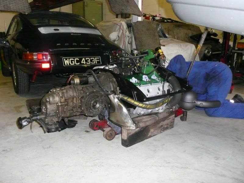
Then with the cars rear raised high on axel stands you can lift the engine and gearbox together, you place the jack pad on the engine crank case just behind the gearbox, in this position it should be balanced with the gearbox pointing up.
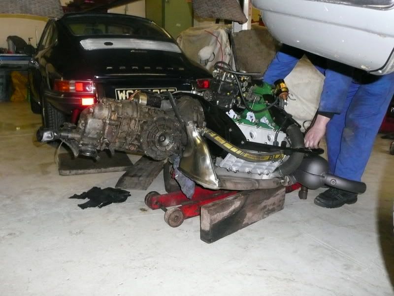
4 bolts later it’s in. Be careful that you do not foul the throttle cables or speedo drive and ensure the clutch cable is not jammed as you jack the engine and gearbox into position.
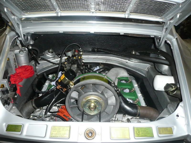
just needed to bolt up the drive shafts and plumb up the oil lines nearly there.
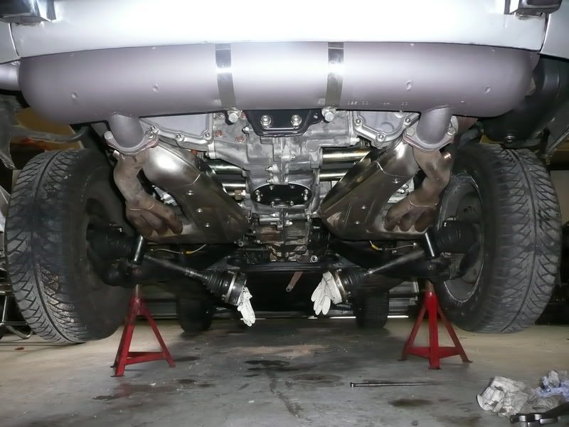
I did a suspension set as well today as I have installed new elephant bushes all round so it should be better all in all respects

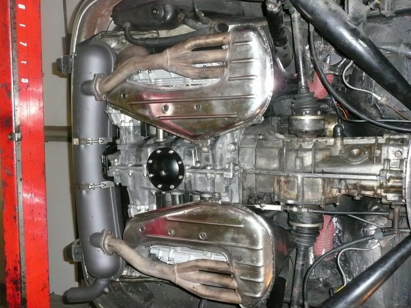
Might just get it started soon.
Posted: Thu Nov 08, 2007 9:25 pm
by hot66
the exciting bit John
Look forward to seeing how this runs. I think you need to run her in on a sunny day across the Ribblehead

Remember to reconnect the speedo cable