

1965 Hillman Imp with Honda Goldwing flat 6. Gordon Murray has contacted me with advice !!!
Moderator: Bootsy
-
misteralz
- DDK rules my life!
- Posts: 1095
- Joined: Wed Mar 06, 2013 12:10 pm
Re: 1965 Hillman Imp with Honda Goldwing flat 6. Road trip.
Amazing stuff. Recognise some of those locations from when we were there on Honeymoon. I'd love to go back.
-
yoeddynz
- DDK addict
- Posts: 135
- Joined: Wed Feb 01, 2023 9:02 am
Re: 1965 Hillman Imp with Honda Goldwing flat 6. Road trip.
I bet you'd love to drive those roads in your porsche!
-
stevenery
- DDK addict
- Posts: 103
- Joined: Tue Jul 20, 2010 6:31 pm
- Location: Oxford
Re: 1965 Hillman Imp with Honda Goldwing flat 6. Road trip.
Really nice landscapes! Great to see you enjoying yourselves. Have you sold all your Micras now? I hope your 3rd exhaust iteration is just a 911 box!
-
yoeddynz
- DDK addict
- Posts: 135
- Joined: Wed Feb 01, 2023 9:02 am
Re: 1965 Hillman Imp with Honda Goldwing flat 6. Road trip.
Cheers Steve.
Yeah the micra has gone, replaced by a Nissan Z11 cube
Still designing the next box. A porsche box wouldn't fit in the tiny space I have (nor could I afford one either)
Yeah the micra has gone, replaced by a Nissan Z11 cube
Still designing the next box. A porsche box wouldn't fit in the tiny space I have (nor could I afford one either)
-
yoeddynz
- DDK addict
- Posts: 135
- Joined: Wed Feb 01, 2023 9:02 am
Re: 1965 Hillman Imp with Honda Goldwing flat 6. Road trip.
Christ, would you look at the time.

Its about time I build another exhaust box. Here comes version 3.0
First I brought version 1.3 in from the garage. This box took me ages to make. Quite involved. By the time I'd got to 1.3 it was pretty good for sound but too fumy with the centre exit exhaust and not flat sixy enough. I took the lid off and looked inside.
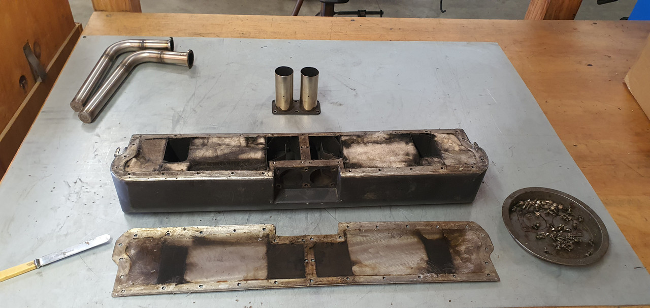
Then this happened.
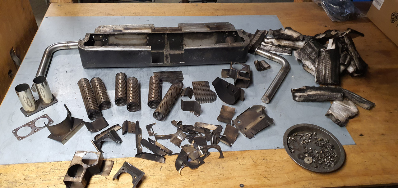
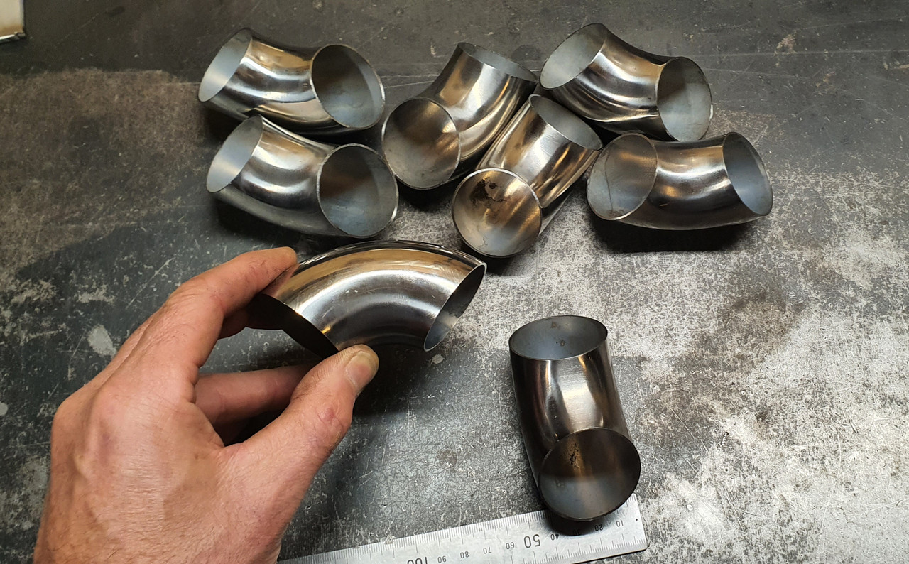
No going back now. I welded in some stainless to cover the hole created when removing the centre exits. It was now a simple box again and ready for filling. These arrived in the post all the way from China. I'm constantly impressed with the quality of these. I got eight of them landed for not much more than the price of one at 'trade' from my stainless supplier.
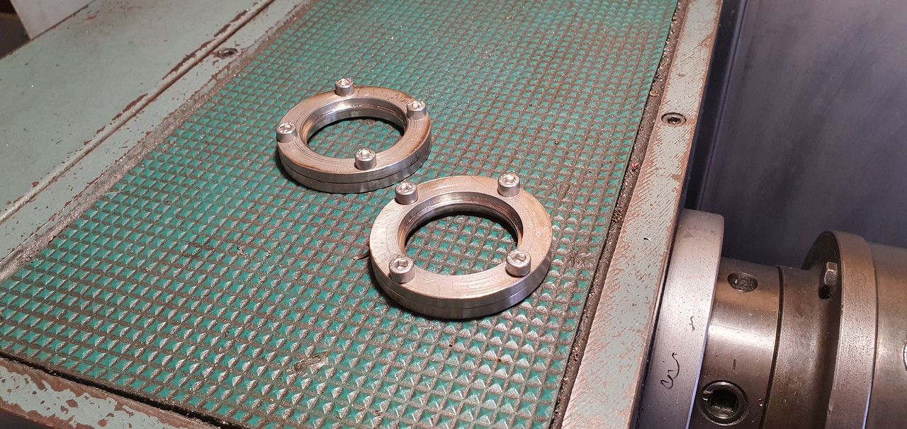
Before playing with elbows I machined up some more flanges for the new tailpipes. These were later welded onto the outlet stubs at each end.
I welded two pairs of elbows together, cut the outside of the curves off and then fired up the yellowhammer workshop Ryobi precision material removal machine centre..
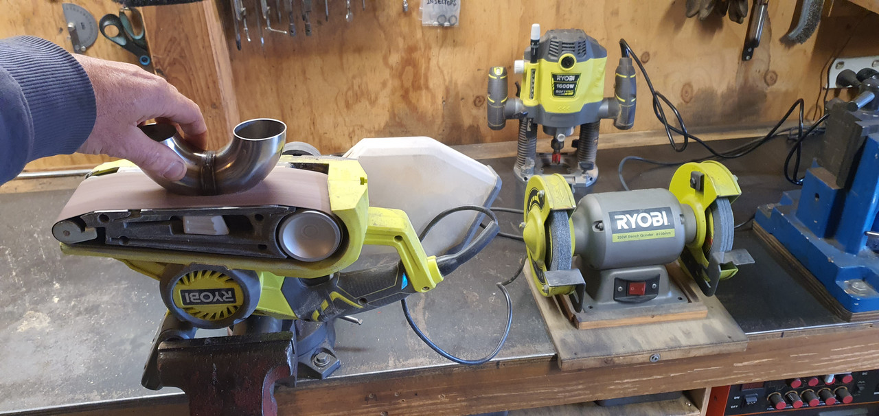
I was so impressed with the quality of finish this machine creates even after checking on the surface table..
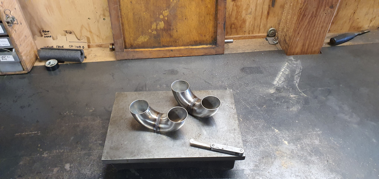
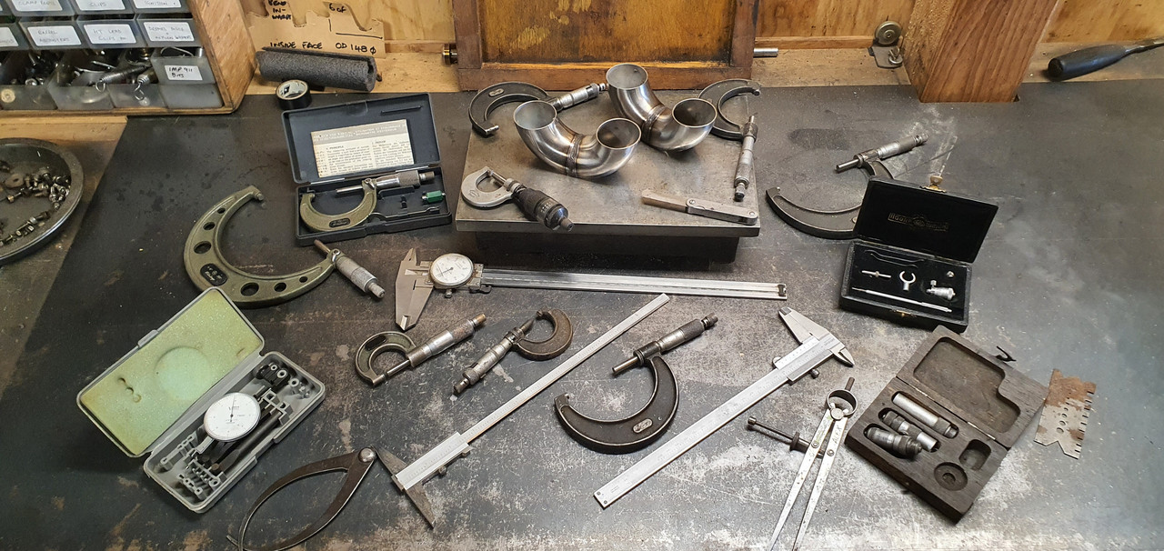
Wow. Amazing. I'd made sure to check all other possible measurements..
I then welded the halves together. I was very happy with how the welding was going..
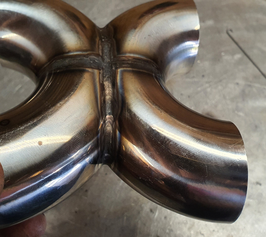
But got a bit slack and a hole appeared. Whoops. You can spot my exceptional filling job here..
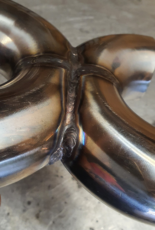
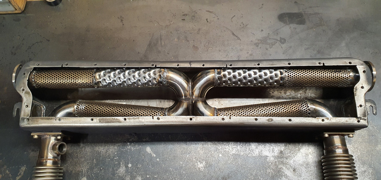
So this X pipe was connected up to some leftover spiral punch silencer tube and some of the perforated tube I made, pinched from box 1.3. Its a very simple layout ..
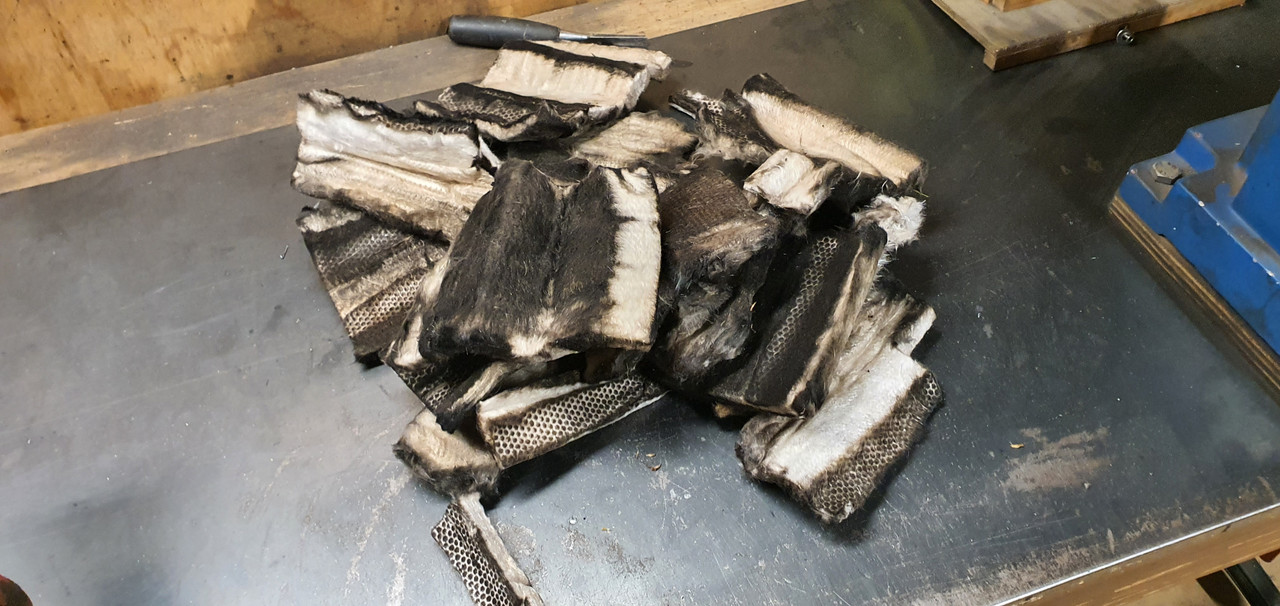
The glass fibre silencer packing pulled from box 1.3 was still in excellent condition...
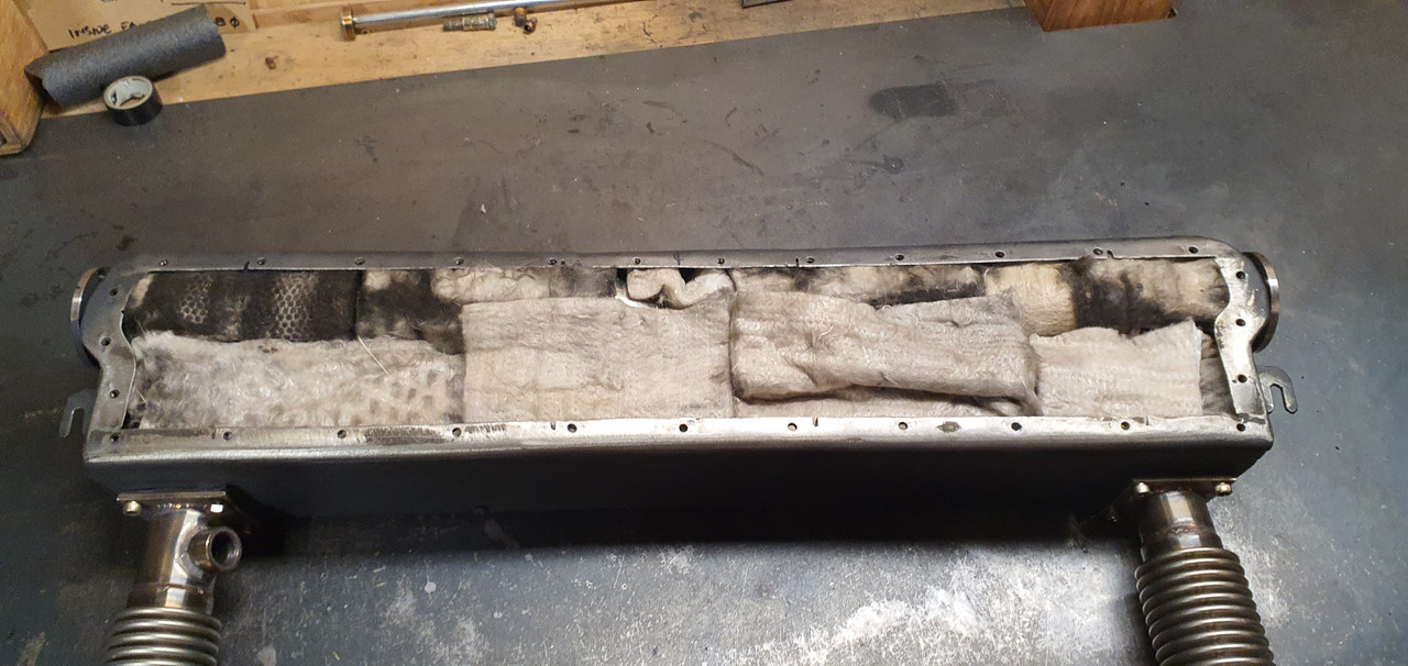
A game of 'Itchy Jigsaw' was played with the pieces until the box was full.
Sealed and bolted down the lid..
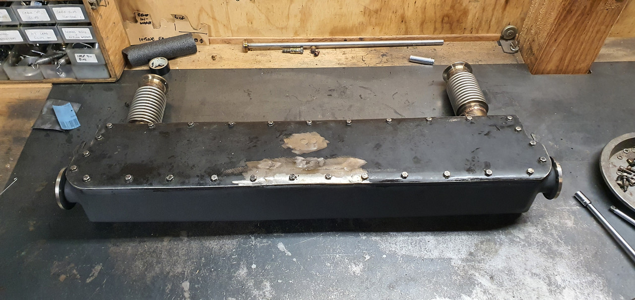
I deliberated for a fairly short amount of time on what form the tail pipes would take. Ended up with an elbow on each end and gave the pipe surfaces an 'easy care' wire brushed finish.
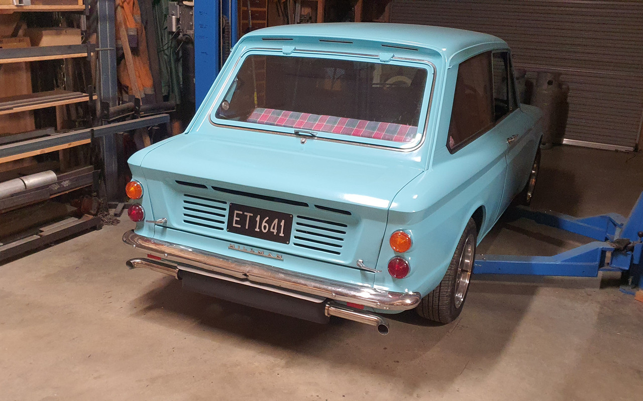
Before the big exciting start up this morning a nice coffee was had. Then we took some vids..
https://www.youtube.com/watch?v=WNlAbapqtYg
Much better!!! In fact I'm really happy with this one. Its got a lovely flat six burble at idle, which could be improved if I lower the idle rpm - currently sits at about 800-825. Its smooth and quite subtle. Could be louder with a bit less packing crammed in.
At cruise its nice and burbly, although again, it could be louder. However I've only heard it from inside at cruise so far. There is absolutely no droning at any point
Once its opened up its lovely. Has a nice wail. Its so fun to drive fast with the revs up. Very smooth.
Only issue is the fumes. Exhaust gases from rear facing exits are still getting sucked into the low pressure zone behind the car and drawn into the cabin when our windows are down. So my next modification (Version 3.1) will be new exits angled off at 45 degrees - sort of like this..
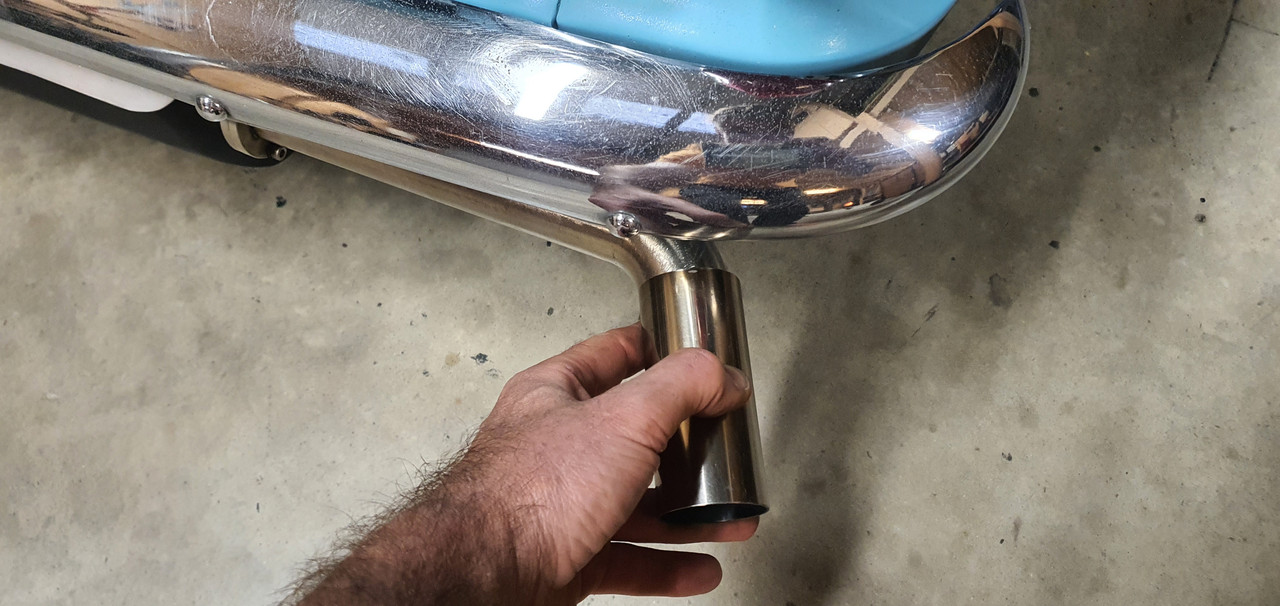
I still love the look of the twin centre exit exhaust on version 1.3 but I think the exits separated like it is now helps accentuate the flat six sound. The actual box design and general look could be improved further, possibly with a neat perforated heat shield ?
But yeah. Very happy with this setup. It might be a keeper.
Its about time I build another exhaust box. Here comes version 3.0
First I brought version 1.3 in from the garage. This box took me ages to make. Quite involved. By the time I'd got to 1.3 it was pretty good for sound but too fumy with the centre exit exhaust and not flat sixy enough. I took the lid off and looked inside.
Then this happened.
No going back now. I welded in some stainless to cover the hole created when removing the centre exits. It was now a simple box again and ready for filling. These arrived in the post all the way from China. I'm constantly impressed with the quality of these. I got eight of them landed for not much more than the price of one at 'trade' from my stainless supplier.
Before playing with elbows I machined up some more flanges for the new tailpipes. These were later welded onto the outlet stubs at each end.
I welded two pairs of elbows together, cut the outside of the curves off and then fired up the yellowhammer workshop Ryobi precision material removal machine centre..
I was so impressed with the quality of finish this machine creates even after checking on the surface table..
Wow. Amazing. I'd made sure to check all other possible measurements..
I then welded the halves together. I was very happy with how the welding was going..
But got a bit slack and a hole appeared. Whoops. You can spot my exceptional filling job here..
So this X pipe was connected up to some leftover spiral punch silencer tube and some of the perforated tube I made, pinched from box 1.3. Its a very simple layout ..
The glass fibre silencer packing pulled from box 1.3 was still in excellent condition...
A game of 'Itchy Jigsaw' was played with the pieces until the box was full.
Sealed and bolted down the lid..
I deliberated for a fairly short amount of time on what form the tail pipes would take. Ended up with an elbow on each end and gave the pipe surfaces an 'easy care' wire brushed finish.
Before the big exciting start up this morning a nice coffee was had. Then we took some vids..
https://www.youtube.com/watch?v=WNlAbapqtYg
Much better!!! In fact I'm really happy with this one. Its got a lovely flat six burble at idle, which could be improved if I lower the idle rpm - currently sits at about 800-825. Its smooth and quite subtle. Could be louder with a bit less packing crammed in.
At cruise its nice and burbly, although again, it could be louder. However I've only heard it from inside at cruise so far. There is absolutely no droning at any point
Once its opened up its lovely. Has a nice wail. Its so fun to drive fast with the revs up. Very smooth.
Only issue is the fumes. Exhaust gases from rear facing exits are still getting sucked into the low pressure zone behind the car and drawn into the cabin when our windows are down. So my next modification (Version 3.1) will be new exits angled off at 45 degrees - sort of like this..
I still love the look of the twin centre exit exhaust on version 1.3 but I think the exits separated like it is now helps accentuate the flat six sound. The actual box design and general look could be improved further, possibly with a neat perforated heat shield ?
But yeah. Very happy with this setup. It might be a keeper.
-
911hillclimber
- Nurse, I think I need some assistance
- Posts: 20688
- Joined: Mon Mar 10, 2008 6:26 pm
- Location: West Midlands
Re: 1965 Hillman Imp with Honda Goldwing flat 6. Road trip.
Welcome back!
That flow pattern looks nice and simple, sign of a good design imho.
That flow pattern looks nice and simple, sign of a good design imho.
73T 911 Coupe, road/hillclimber 3.2L
Lola t 492 / 3.2 hillclimb racer
Boxster 987 Gen II 2.9
Lola t 492 / 3.2 hillclimb racer
Boxster 987 Gen II 2.9
-
yoeddynz
- DDK addict
- Posts: 135
- Joined: Wed Feb 01, 2023 9:02 am
Re: 1965 Hillman Imp with Honda Goldwing flat 6. Road trip.
Thanks man. Yeah its a much simpler design and certainly seems to work. Its also possibly lighter - I think it should be but I forgot to weigh it before fitting.
Now how do I go about adding air cooled clatter
Now how do I go about adding air cooled clatter
-
yoeddynz
- DDK addict
- Posts: 135
- Joined: Wed Feb 01, 2023 9:02 am
Re: 1965 Hillman Imp with Honda Goldwing flat 6. Exhaust silencer version 3.0
Very small update. So whilst I have been making exhausts to create certain noises I have also been chasing other noises I don't want.
First off though is a pic of exhaust version 3.0 with added 0.1 extensions...
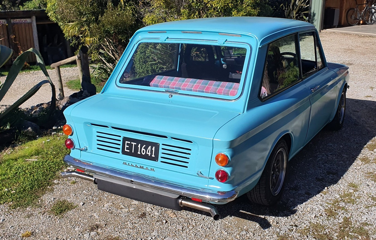
Pointing out at roughly 45 degrees and extended further these have so far seemed to have really improved the fumage issue. I'll have to do more driving with the window down to confirm. I still want to spend some time doing more tuning as well, smooth out the map and get rid of the really rich spikes sometimes seen.
So the other noises I mentioned?
Well for roughly the last couple of months I have noticed that after startup whilst in warming up and the idle is high there's a funny whirring sound coming from somewhere in the engine. It was hard to tell where when the car was sat on the ground. I'd look underneath and try my best to pinpoint it but it's tricky with all of the general mechanical sounds bouncing off the ground. I was thinking the only thing it might be was the chain drives for the oil pump having bedded creating a bit of slack on the free side and somehow whirring.
The release bearing was also occasionally making a tinkling sound, or possibly its actually the 3 bearings I had fitted in my 'thrust bearing 2000' assembly that resides between the back plate and the flywheel.
Oh and the new exhaust has a tiny rattle on one side. Only noticeable if I smack the box up on that side (a quick lesson was learned not to do this when its searing hot) and I suspect its actually the tube the runs through the flexi joint just touching. Hopefully I can rectify it by adjusting the bobbin height on that side.
But this whirring sound? It goes away somewhat when the idle drops as the engine warms up and I cant hear over the exhaust from then on. So this morning I started the car up, moved it from its garage and out into the sunshine. I let it warm up. Then moved it inside and onto the hoist. Once up in the air I started the car (using my go go gadget arms) and listened from underneath. Being fairly warm the sound was barely audible until I reached up with my arm to the throttle body and gave the engine a rev. Bingo- there it is! Its in the cambelt cover! Its a flappy whirr. A rubbing flappy whirr.
I let the engine cool down, went for a pushbike ride and then this evening it was off with the cover, which luckily is super easy to remove once the alternator pulley is removed from the crank.
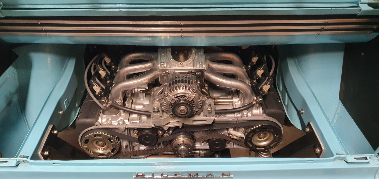
Zoom in..
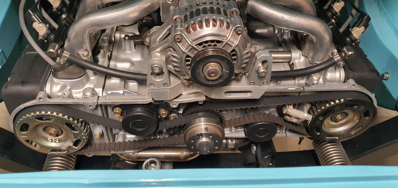
That bottom belt run on the left was a bit loose. Not terribly but certainly a bit more than the specified 5-7mm Honda advise. When the engine is cold its free to move that amount. I presume as it warms up it gets a touch tighter (boxxer engines 'grow' a little in width as they warm) The manual states that if the belts are too loose they can flap against the cover. Too tight and they whine. I could see where its been rubbing on the cover..
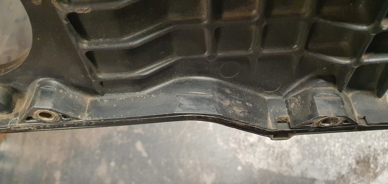
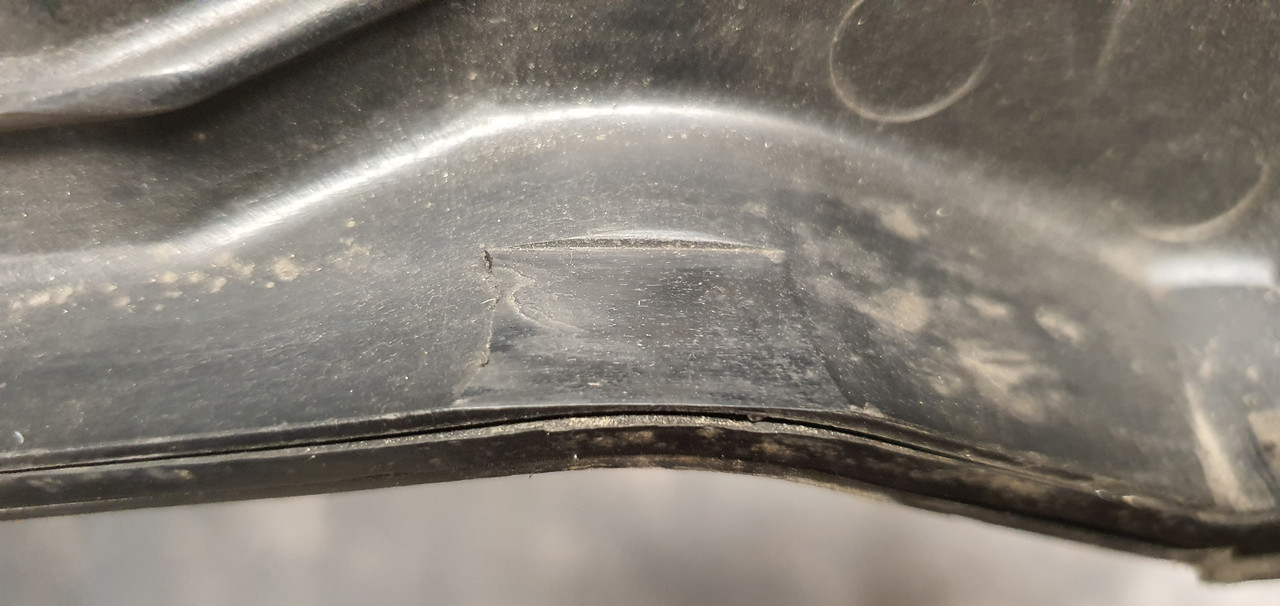
I have now tightened both belts just a smidge. Its a bit tricky to exactly measure 5-7mm but they seem about right. Cover back on and I'll test it tomorrow. (I'm not keen on filling the workshop up with warm up fumes tonight when our bedroom door is about in line with the roof of the Imp)
Also to note. This morning was an especially cold 'late summer' start to the day of only 2 degrees.
After I started the car later in the morning and moved it out (around 12 degrees then) I opened the engine bay lid for a look while it was warming up. I soon spotted one of the injector rail hose clips at the front was leaking. I promptly tightened it up and leak be gone.
I can only presume the rubber hoses had shrunk ever so slightly in the cold night and allowed the fuel at 40 psi to weep past. I checked all the other fuel line hose clips in the engine bay and one other was slightly loose. I must check the ones in the frunk too!
First off though is a pic of exhaust version 3.0 with added 0.1 extensions...
Pointing out at roughly 45 degrees and extended further these have so far seemed to have really improved the fumage issue. I'll have to do more driving with the window down to confirm. I still want to spend some time doing more tuning as well, smooth out the map and get rid of the really rich spikes sometimes seen.
So the other noises I mentioned?
Well for roughly the last couple of months I have noticed that after startup whilst in warming up and the idle is high there's a funny whirring sound coming from somewhere in the engine. It was hard to tell where when the car was sat on the ground. I'd look underneath and try my best to pinpoint it but it's tricky with all of the general mechanical sounds bouncing off the ground. I was thinking the only thing it might be was the chain drives for the oil pump having bedded creating a bit of slack on the free side and somehow whirring.
The release bearing was also occasionally making a tinkling sound, or possibly its actually the 3 bearings I had fitted in my 'thrust bearing 2000' assembly that resides between the back plate and the flywheel.
Oh and the new exhaust has a tiny rattle on one side. Only noticeable if I smack the box up on that side (a quick lesson was learned not to do this when its searing hot) and I suspect its actually the tube the runs through the flexi joint just touching. Hopefully I can rectify it by adjusting the bobbin height on that side.
But this whirring sound? It goes away somewhat when the idle drops as the engine warms up and I cant hear over the exhaust from then on. So this morning I started the car up, moved it from its garage and out into the sunshine. I let it warm up. Then moved it inside and onto the hoist. Once up in the air I started the car (using my go go gadget arms) and listened from underneath. Being fairly warm the sound was barely audible until I reached up with my arm to the throttle body and gave the engine a rev. Bingo- there it is! Its in the cambelt cover! Its a flappy whirr. A rubbing flappy whirr.
I let the engine cool down, went for a pushbike ride and then this evening it was off with the cover, which luckily is super easy to remove once the alternator pulley is removed from the crank.
Zoom in..
That bottom belt run on the left was a bit loose. Not terribly but certainly a bit more than the specified 5-7mm Honda advise. When the engine is cold its free to move that amount. I presume as it warms up it gets a touch tighter (boxxer engines 'grow' a little in width as they warm) The manual states that if the belts are too loose they can flap against the cover. Too tight and they whine. I could see where its been rubbing on the cover..
I have now tightened both belts just a smidge. Its a bit tricky to exactly measure 5-7mm but they seem about right. Cover back on and I'll test it tomorrow. (I'm not keen on filling the workshop up with warm up fumes tonight when our bedroom door is about in line with the roof of the Imp)
Also to note. This morning was an especially cold 'late summer' start to the day of only 2 degrees.
After I started the car later in the morning and moved it out (around 12 degrees then) I opened the engine bay lid for a look while it was warming up. I soon spotted one of the injector rail hose clips at the front was leaking. I promptly tightened it up and leak be gone.
I can only presume the rubber hoses had shrunk ever so slightly in the cold night and allowed the fuel at 40 psi to weep past. I checked all the other fuel line hose clips in the engine bay and one other was slightly loose. I must check the ones in the frunk too!
-
yoeddynz
- DDK addict
- Posts: 135
- Joined: Wed Feb 01, 2023 9:02 am
Re: 1965 Hillman Imp with Honda Goldwing flat 6. Exhaust silencer version 3.0
We've had a fair amount of rainy weather recently. Last weekend we had a big atmospheric river and got 320mm over 36 hours. Lots of local flooding and quite a few unlucky souls have lost quite a lot. For us it was just some of our driveway getting washed downhill and a few trees coming down so mustn't grumble.
Anyway- it was a good excuse to stay indoors, crank the fireplace, music, espresso machine and tinker with the Imp.
Ages ago I had picked up these Mitsubishi V6 pajaro instruments from the wreckers..
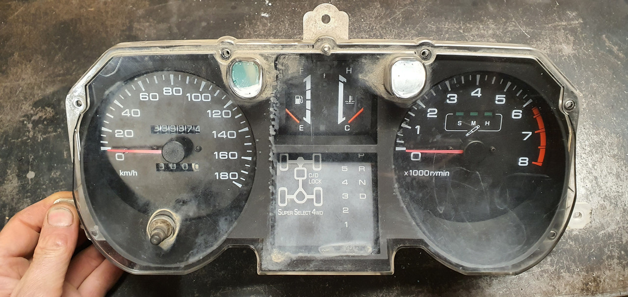
In previous posts I had stripped them down, chopped off all the excess bits not needed (trip meter etc) so they'd fit into some housings I machined out of thick walled alloy tube. I had found a Toyota speed sensor that I adapted to fit my Subaru transmission. Wired them up and checked it worked, which it did well but it was reading a good 10 ~ 15kph out. I then packed the lot away in a box and stashed it away.
It was time to crack on and make something of them. First job was to work out an accurate speedo face to suit the setup. I cut a circle of paper, fit it in place and we went driving. Using a GPS speedo we marked out all the various speed points.
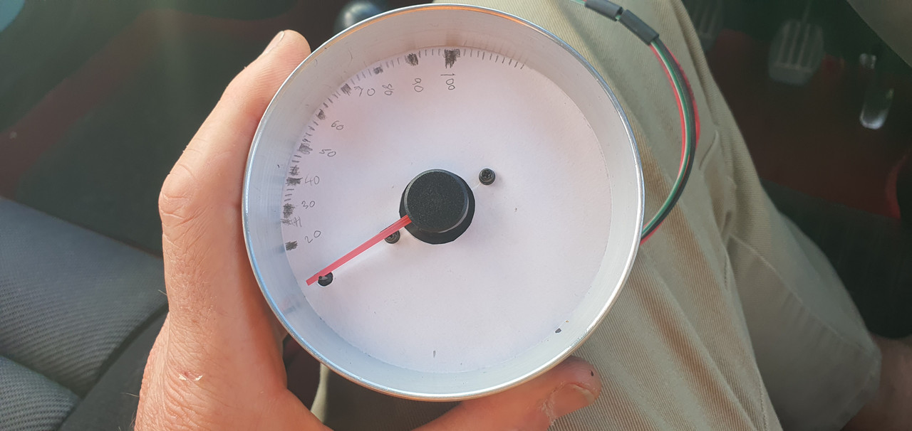
Then I used a program online...
https://www.blocklayer.com/gauge-templates
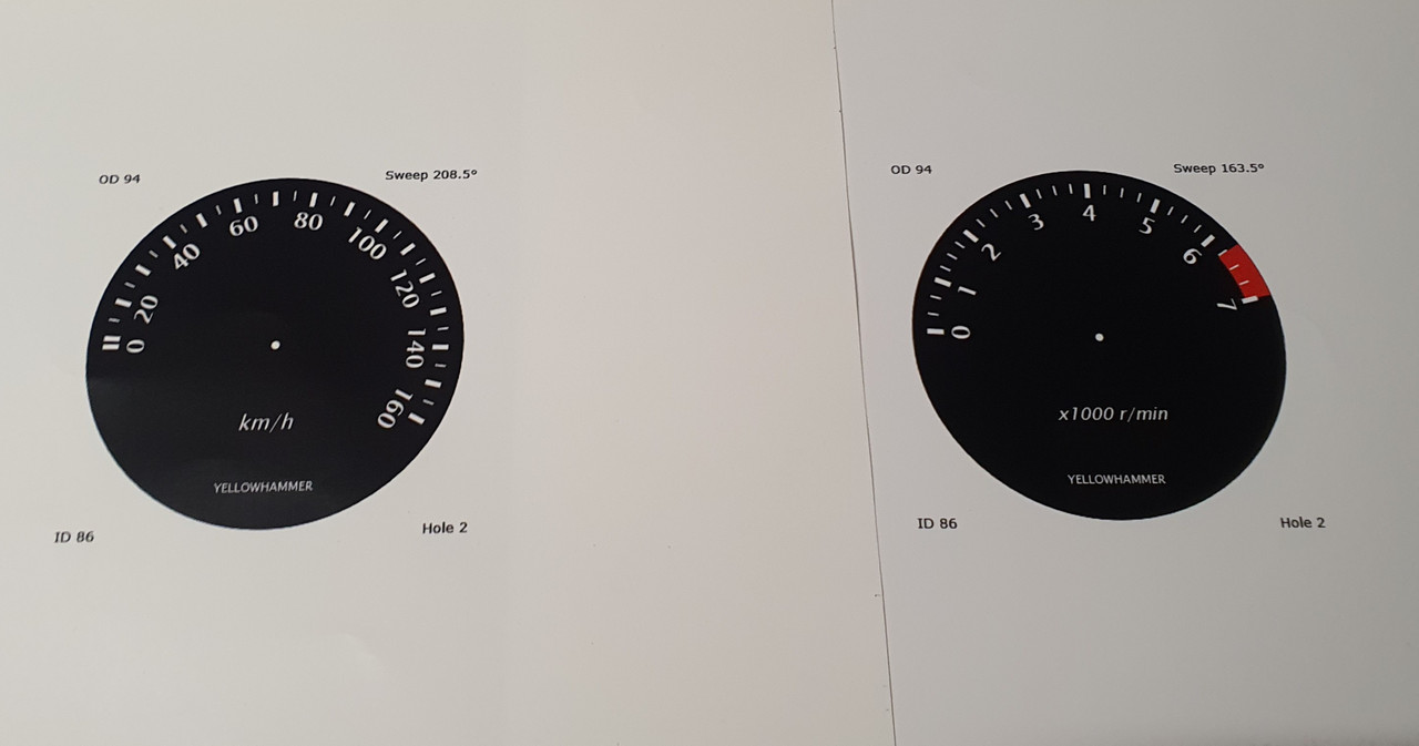
..however it didn't create what I wanted as most speedos have non linear markings, especially 0-20. I chatted to the fella who was running the website and he added some custom bins into the program to suit and it worked great. We printed off a new face that matched the hand drawn one and went for a drive to check it was good..
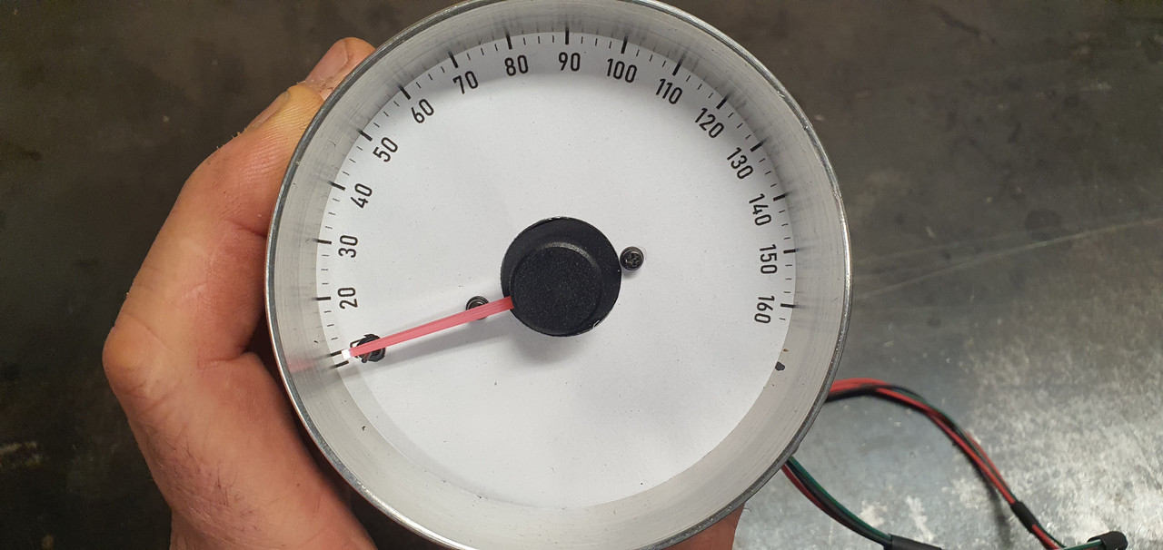
Then I spent some time having fun creating some gauge faces. I had a particular style in mind. My current design turned out pretty boring given how far one could go with the variety of fonts, colours, images, text but I wanted a 60s/70s look to suit the car and dash layout I have in mind. Fun thing is I can change it easily now I have a saved accurate template.
Used the big printer we have that barely gets used.
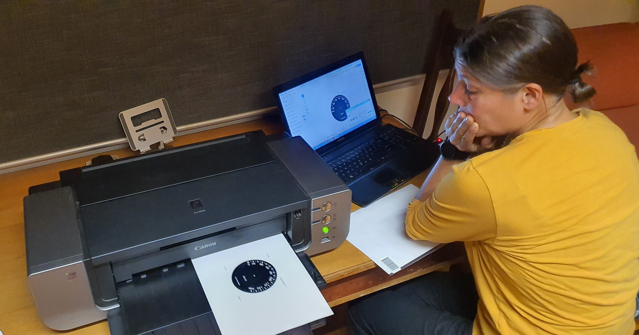
Cut them out to suit. Machined up some tiny wad punches to do the holes.
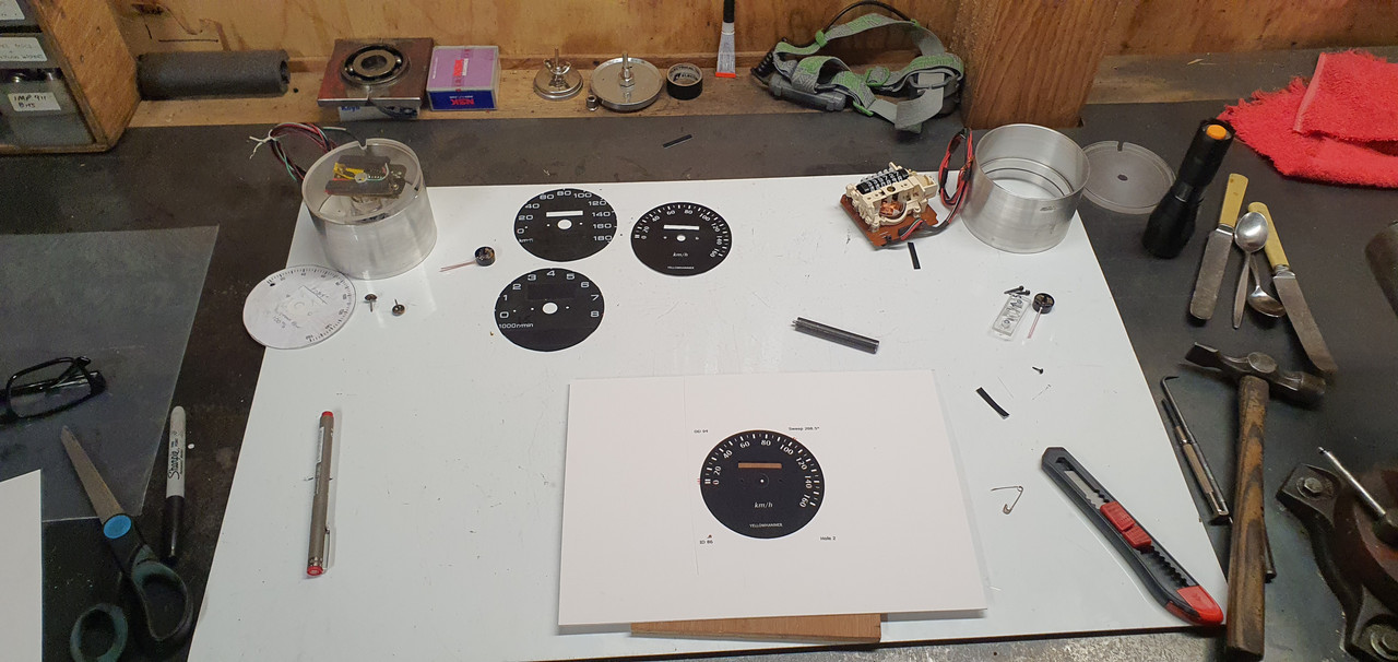
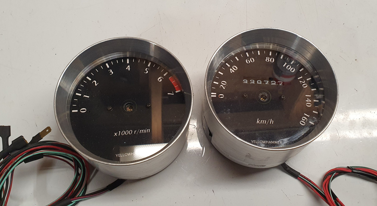
Into the housings.
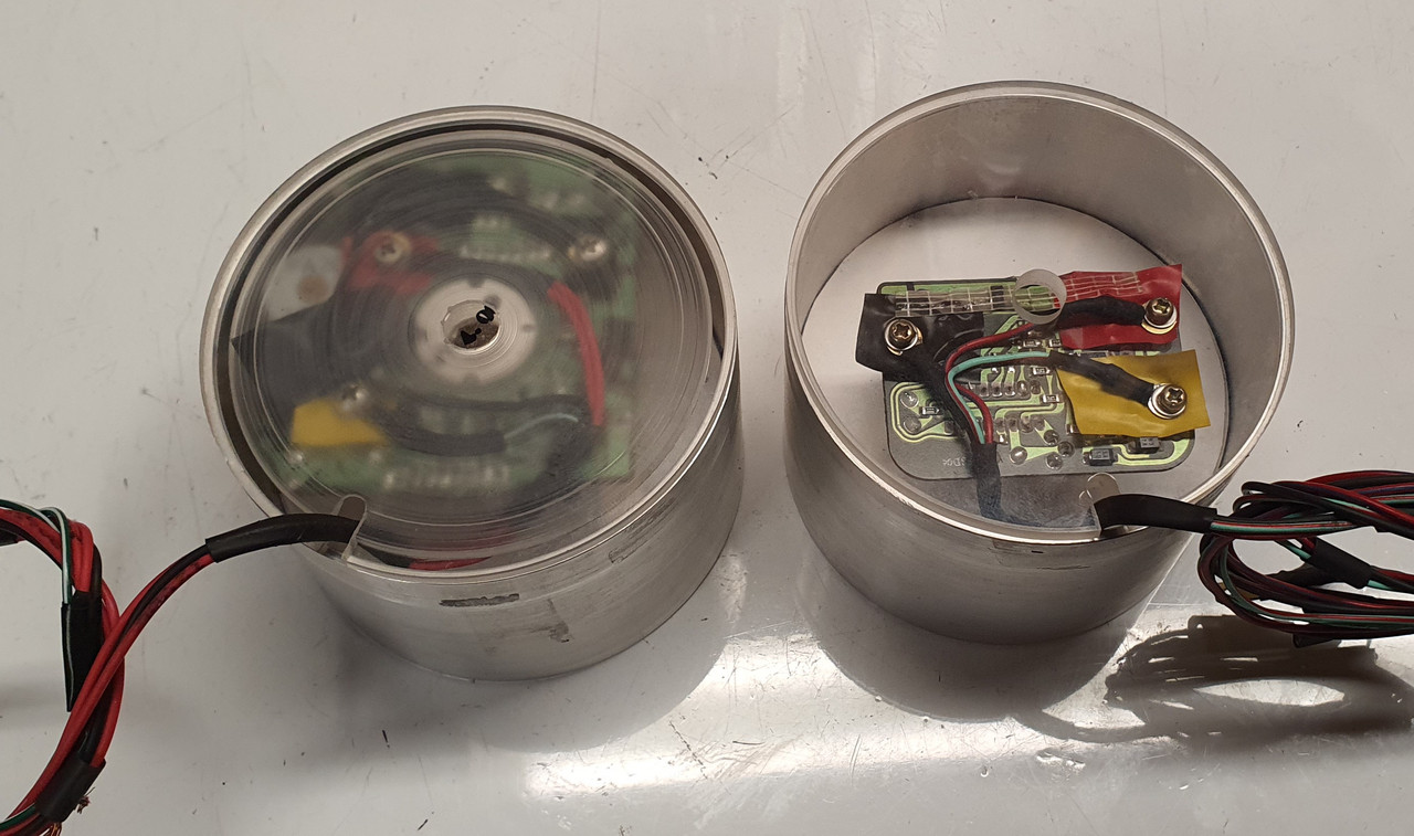
The backside. Later on I'll need to add some led lights to shine through the white font.I'll also re-set the odometer to match the current reading even though it'll be in km from now on. The needles will then go back in place once I have finished all this.
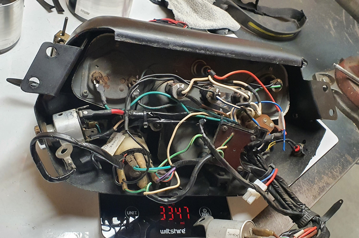
I removed the original Imp dash pads and instrument cluster. Its a heavy bit of kit. Comical wiring layout too.
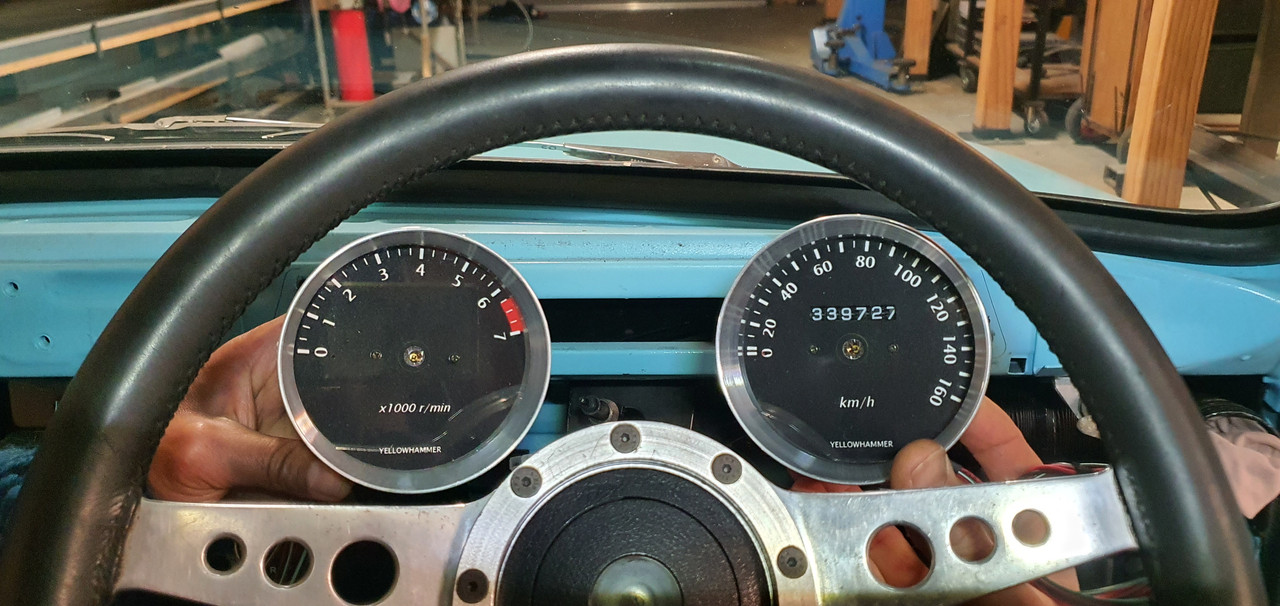
Sat in the car and eyed up how I'd like the gauges to sit. The idea is to build a pod that will work with the original MK1 Imp dash pads which I really do like the style of.
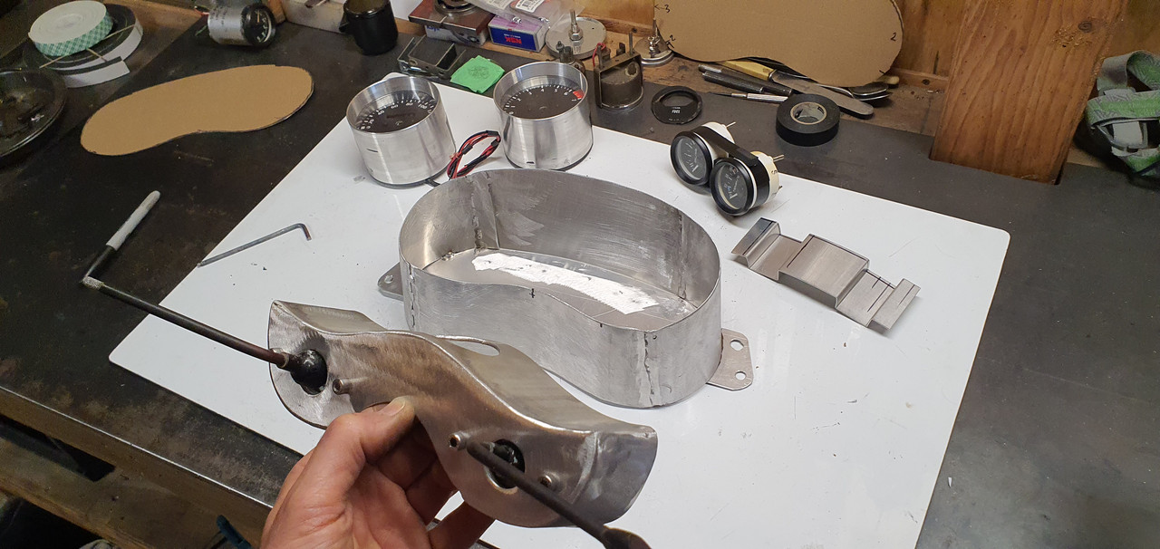
I had part sheet of 1.2mm alloy which I cut, bent, rolled, twisted and tweaked to shape, welding all the bits together doing my very best to try not to create holes. Not the easiest thickness alloy to tig weld but managed ok. I also welded up a bolt on pod that sits below to take the original Imp indicator stalks.
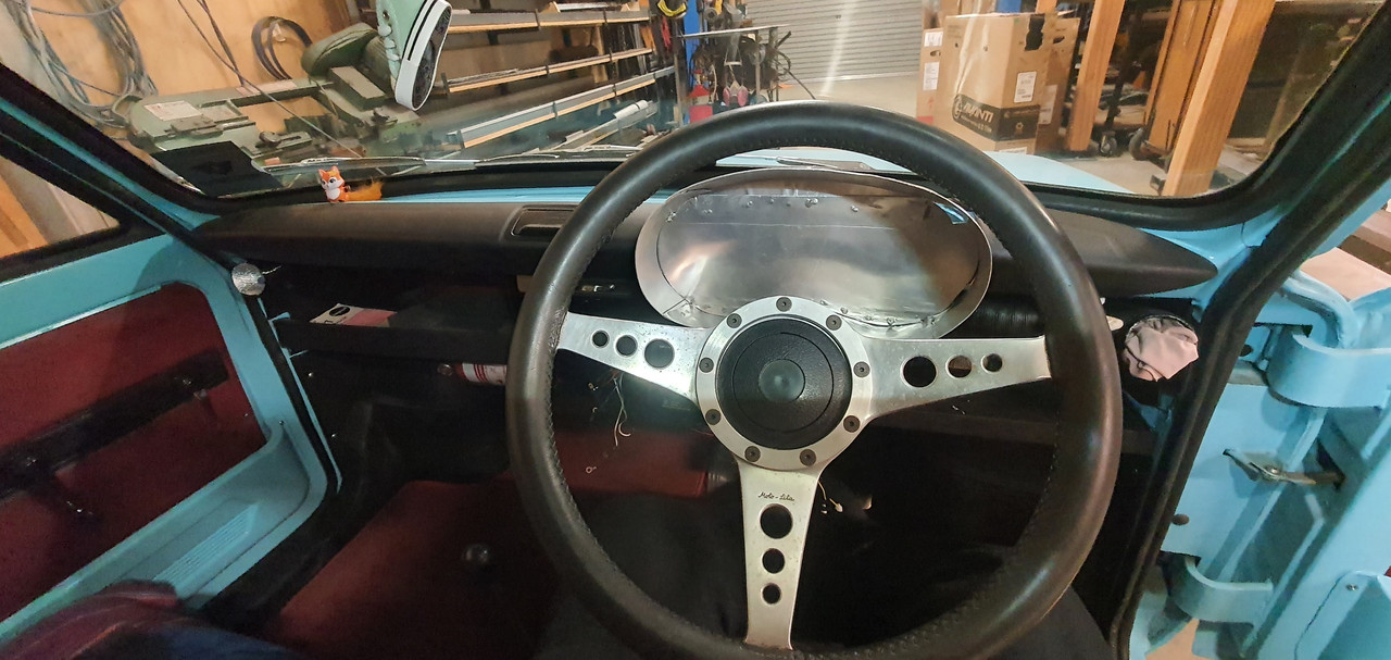
Checked it was ok.
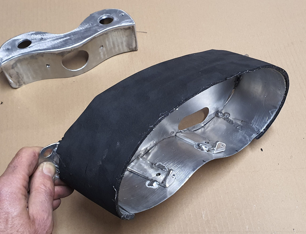
Covered the outside in medium density foam..
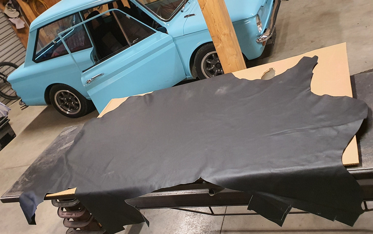
Bought some more cow that local canvas place still had a stash of..
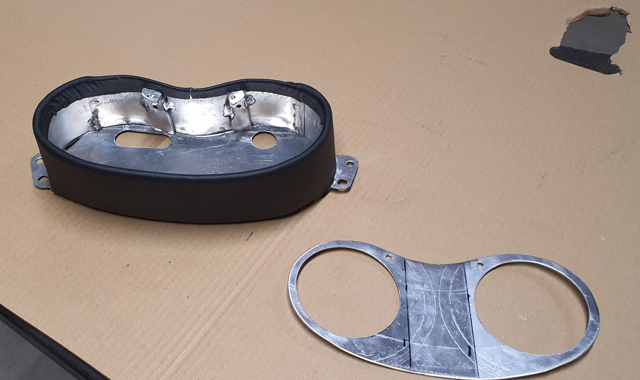
Very carefully cut and glued it in place.
Painted the other alloy parts in etch primer then satin black. Added some tiny warning lamps. Most important gauge, the oil pressure gauge, resides in the middle..
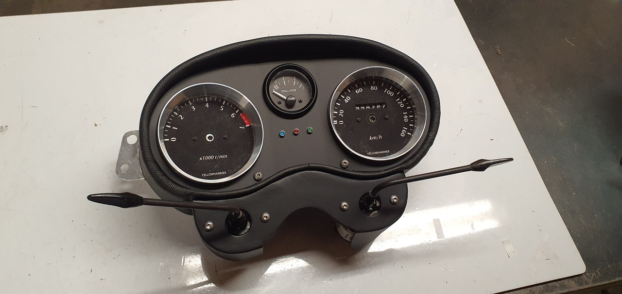
Really happy with the finish. There's a couple of blemishes (tiny knife nick) but overall considering the awkwardness of this build I'm stoked.
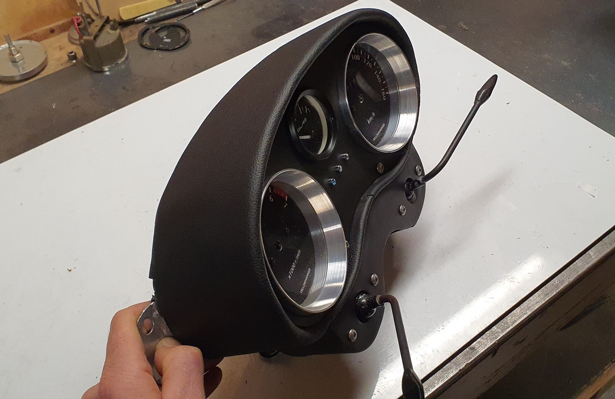
And bolted in place. I can adjust the angles of the gauges quite easily too but its currently good for both of us.
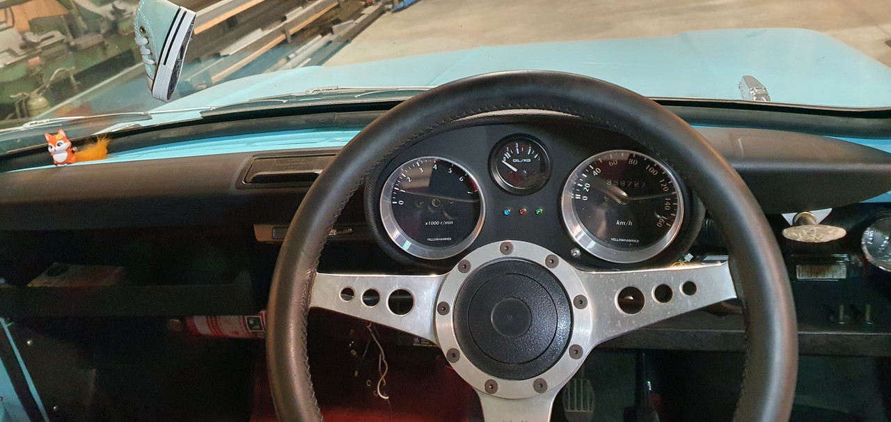
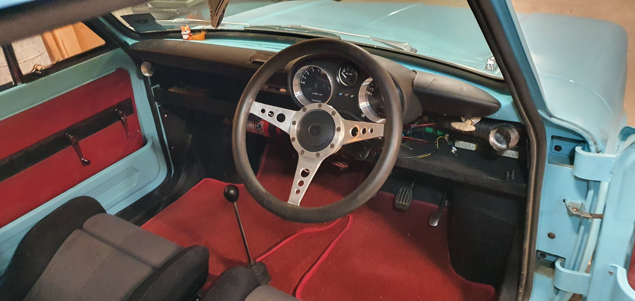
Ties in really nicely with the dash pads..
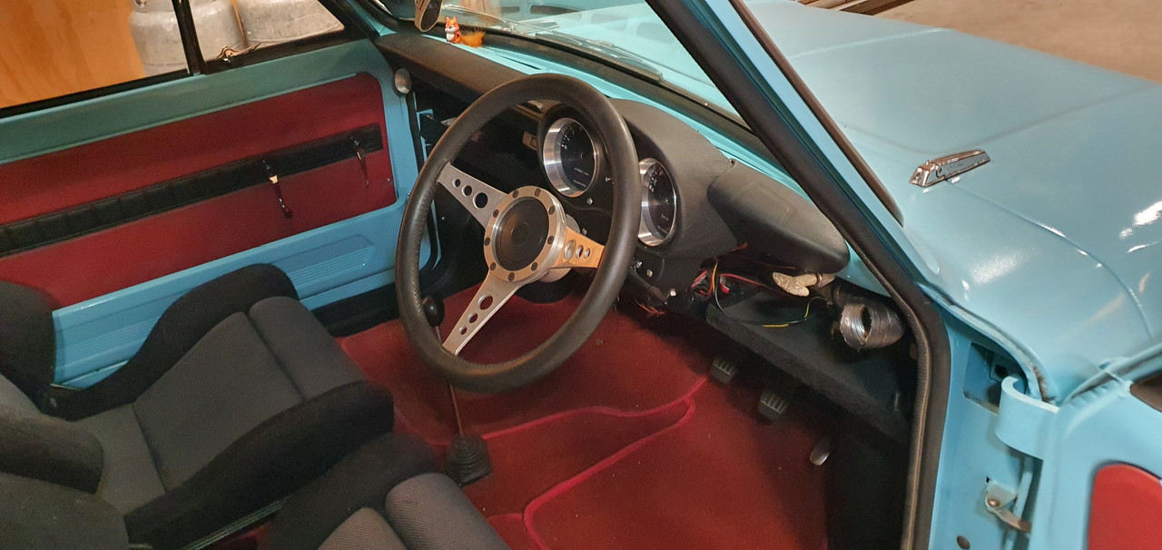
Next job is to sort out the wiring. I'd already made it far more user friendly compared to stock by having added several multi plugs. I'm going to re-do it though and use some smaller wire where I can along with Deutsch plugs. There will be a new dash face below the dash pads that will house 3 gauges, some rocker switches and a Triumph eyeball vent at each end.
Anyway- it was a good excuse to stay indoors, crank the fireplace, music, espresso machine and tinker with the Imp.
Ages ago I had picked up these Mitsubishi V6 pajaro instruments from the wreckers..
In previous posts I had stripped them down, chopped off all the excess bits not needed (trip meter etc) so they'd fit into some housings I machined out of thick walled alloy tube. I had found a Toyota speed sensor that I adapted to fit my Subaru transmission. Wired them up and checked it worked, which it did well but it was reading a good 10 ~ 15kph out. I then packed the lot away in a box and stashed it away.
It was time to crack on and make something of them. First job was to work out an accurate speedo face to suit the setup. I cut a circle of paper, fit it in place and we went driving. Using a GPS speedo we marked out all the various speed points.
Then I used a program online...
https://www.blocklayer.com/gauge-templates
..however it didn't create what I wanted as most speedos have non linear markings, especially 0-20. I chatted to the fella who was running the website and he added some custom bins into the program to suit and it worked great. We printed off a new face that matched the hand drawn one and went for a drive to check it was good..
Then I spent some time having fun creating some gauge faces. I had a particular style in mind. My current design turned out pretty boring given how far one could go with the variety of fonts, colours, images, text but I wanted a 60s/70s look to suit the car and dash layout I have in mind. Fun thing is I can change it easily now I have a saved accurate template.
Used the big printer we have that barely gets used.
Cut them out to suit. Machined up some tiny wad punches to do the holes.
Into the housings.
The backside. Later on I'll need to add some led lights to shine through the white font.I'll also re-set the odometer to match the current reading even though it'll be in km from now on. The needles will then go back in place once I have finished all this.
I removed the original Imp dash pads and instrument cluster. Its a heavy bit of kit. Comical wiring layout too.
Sat in the car and eyed up how I'd like the gauges to sit. The idea is to build a pod that will work with the original MK1 Imp dash pads which I really do like the style of.
I had part sheet of 1.2mm alloy which I cut, bent, rolled, twisted and tweaked to shape, welding all the bits together doing my very best to try not to create holes. Not the easiest thickness alloy to tig weld but managed ok. I also welded up a bolt on pod that sits below to take the original Imp indicator stalks.
Checked it was ok.
Covered the outside in medium density foam..
Bought some more cow that local canvas place still had a stash of..
Very carefully cut and glued it in place.
Painted the other alloy parts in etch primer then satin black. Added some tiny warning lamps. Most important gauge, the oil pressure gauge, resides in the middle..
Really happy with the finish. There's a couple of blemishes (tiny knife nick) but overall considering the awkwardness of this build I'm stoked.
And bolted in place. I can adjust the angles of the gauges quite easily too but its currently good for both of us.
Ties in really nicely with the dash pads..
Next job is to sort out the wiring. I'd already made it far more user friendly compared to stock by having added several multi plugs. I'm going to re-do it though and use some smaller wire where I can along with Deutsch plugs. There will be a new dash face below the dash pads that will house 3 gauges, some rocker switches and a Triumph eyeball vent at each end.
-
911hillclimber
- Nurse, I think I need some assistance
- Posts: 20688
- Joined: Mon Mar 10, 2008 6:26 pm
- Location: West Midlands
Re: 1965 Hillman Imp with Honda Goldwing flat 6. Exhaust silencer version 3.0
That will do very nicely!
73T 911 Coupe, road/hillclimber 3.2L
Lola t 492 / 3.2 hillclimb racer
Boxster 987 Gen II 2.9
Lola t 492 / 3.2 hillclimb racer
Boxster 987 Gen II 2.9
-
yoeddynz
- DDK addict
- Posts: 135
- Joined: Wed Feb 01, 2023 9:02 am
Re: 1965 Hillman Imp with Honda Goldwing flat 6. Exhaust silencer version 3.0
Big post alert
Hannah and I have come back from a lovely 6 week holiday, based mainly in Oxford, UK. Mainly cycling and catching up with Hannahs family. We actually got some really good hot, sunny weather too!
While there I contacted a local to Oxford classic Porsche workshop. I took a train 10 miles north to Bicester and walked from there. What was meant to be a short walk turned into a 20km walk in the sun on a 34 degree day thanks to me following out of date Google maps. Lessons learned that day. But I got there in the end and had a tour around the place. Very friendly staff, very tidy. Some fantastic 911s inc I think at least 3 genuine Carrera RS 2.7s. I took many photos...
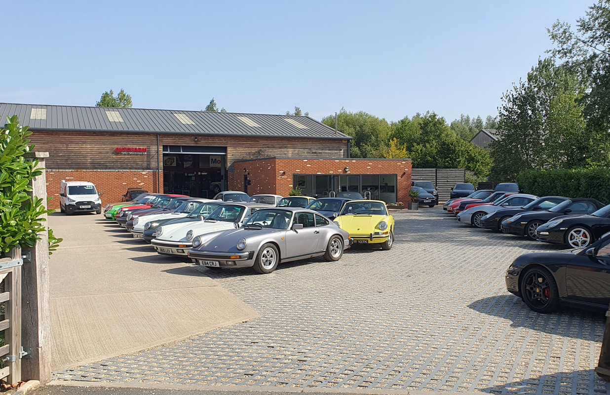
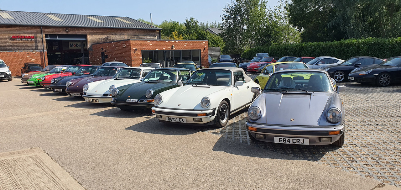
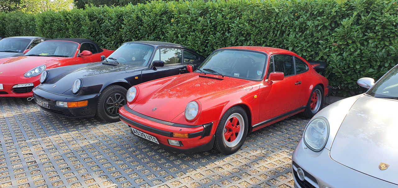
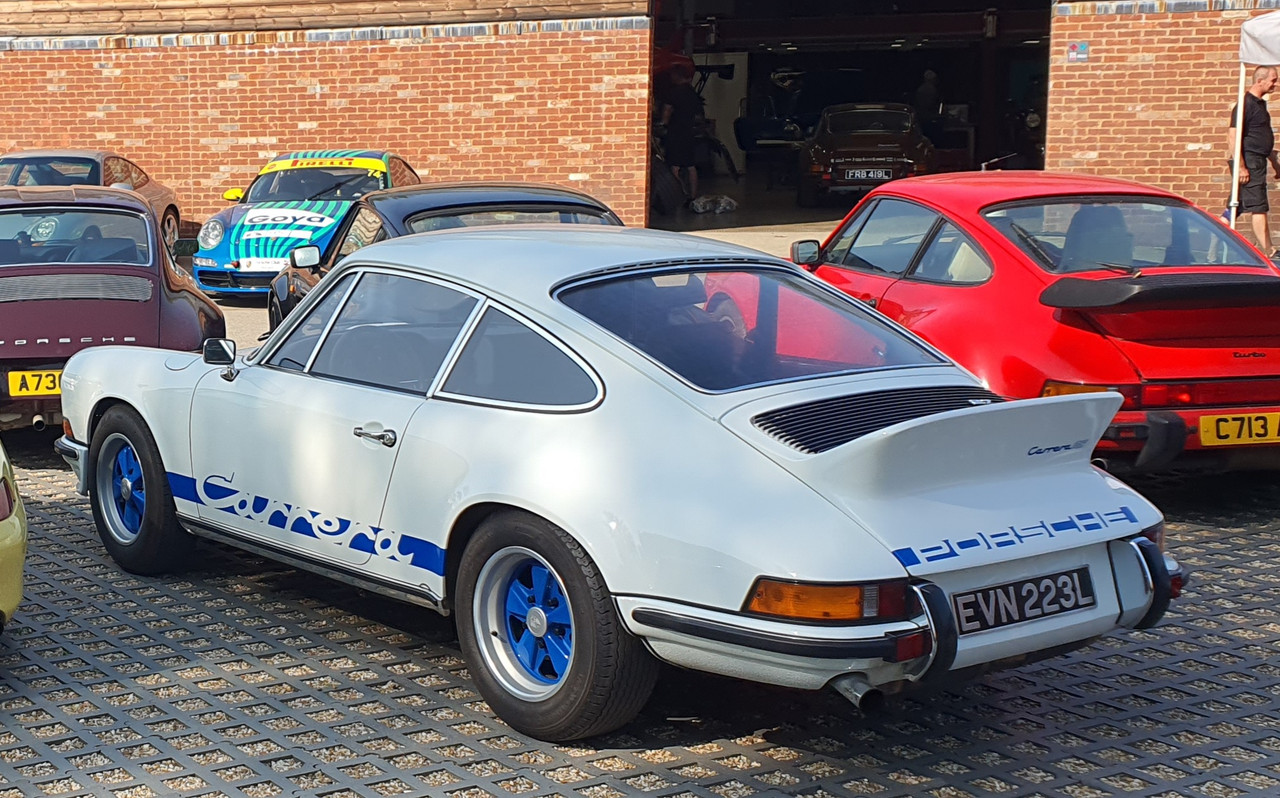
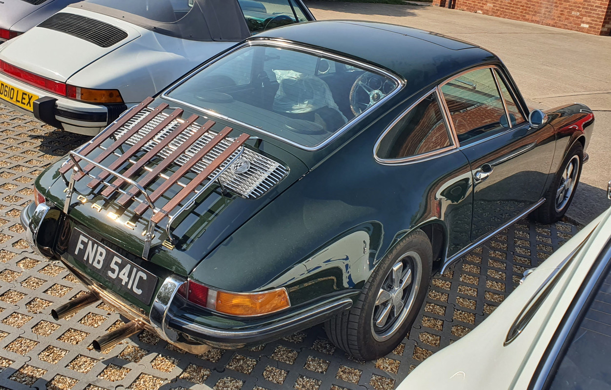

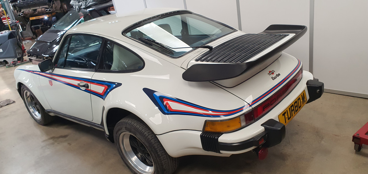
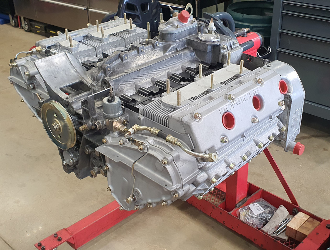
So that was nice.
They are looking for some staff including a metal worker/engineer for the restoration side. If I was still living in Oxford I probably be there in a flash for the experience.
But back to NZ and we were welcomed with a whole load of slip clearing to do. Our place was one of the many local properties to get completely battered by a massive rain event that happened while Hannah and I were on our flight to the UK. Absolute carnage. I'll do a more detailed update on our bushblock thread.
This is one of our driveway entrances..
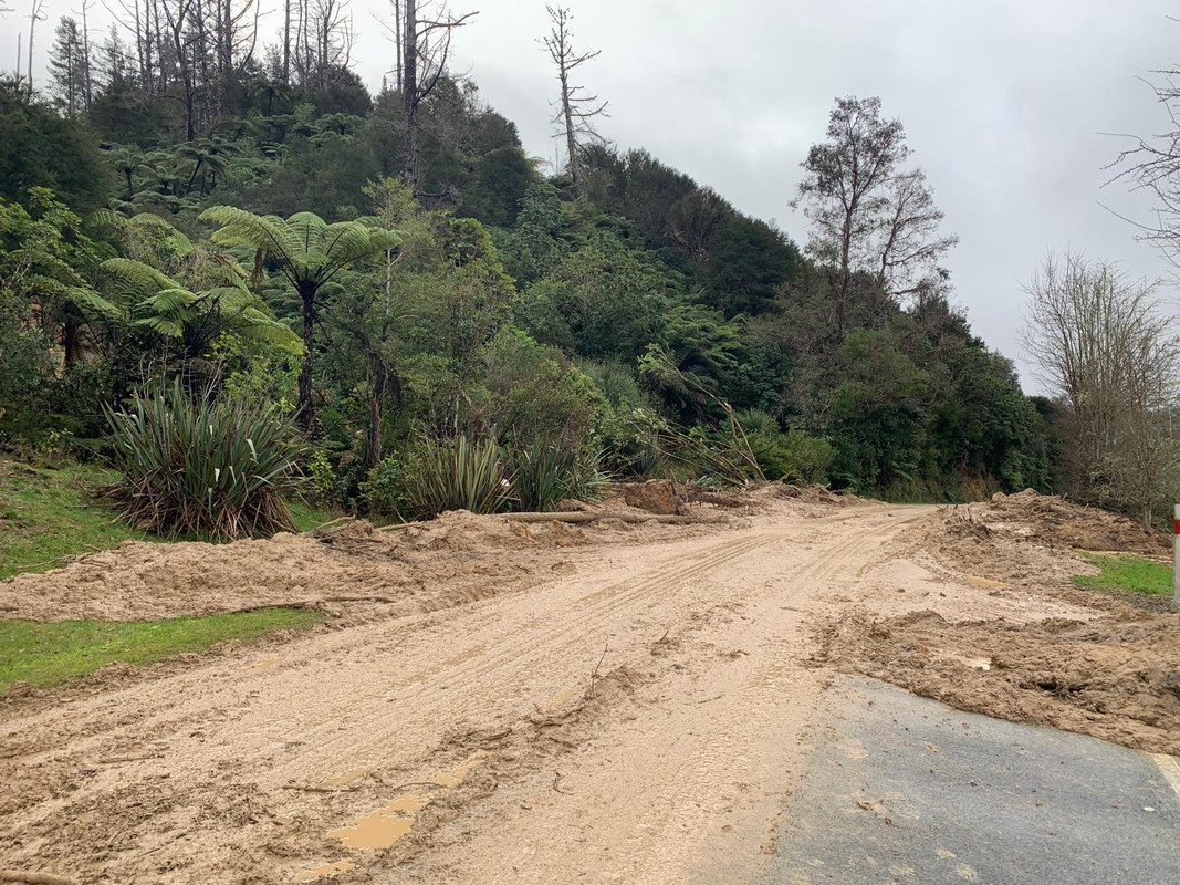
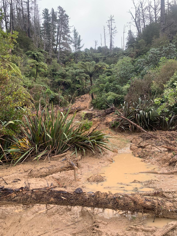
The neighbours place got silt through their house..

Fun times. We've got a lot of clearing to do yet including dealing with this huge tree which floated down on a wave of mud and stopped 3 metres shy of our mailbox..
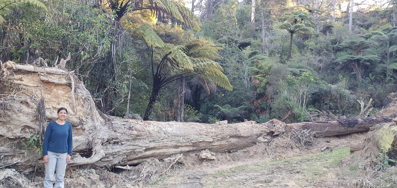
We spent the first week back home fixing our water system which was damaged..

Anyway - that's that. It could have been much worse. Others local to us have lost their houses. Luckily our workshop was fine.
Back to the Imp. My last post was the speedo and rev counter instrument pod build. Next on the list was a new dash which was to include revised switch gear, the other gauges, a pair of Triumph 2500 eyeball vents and an actual glove box rather than this shelf layout as on the passenger side...
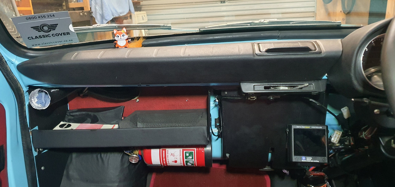
and drivers side..
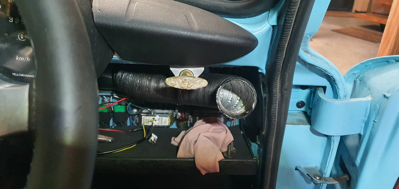
But before making a dash top I needed to sort out lights on my new instruments. I had some rolls of ali express multi coloured led strips.
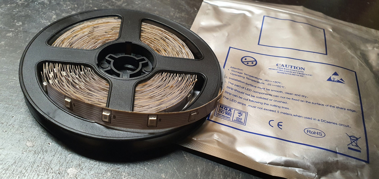
Stuck them on the bench and had a play..
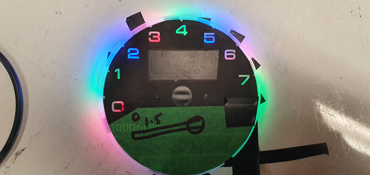
Cool..
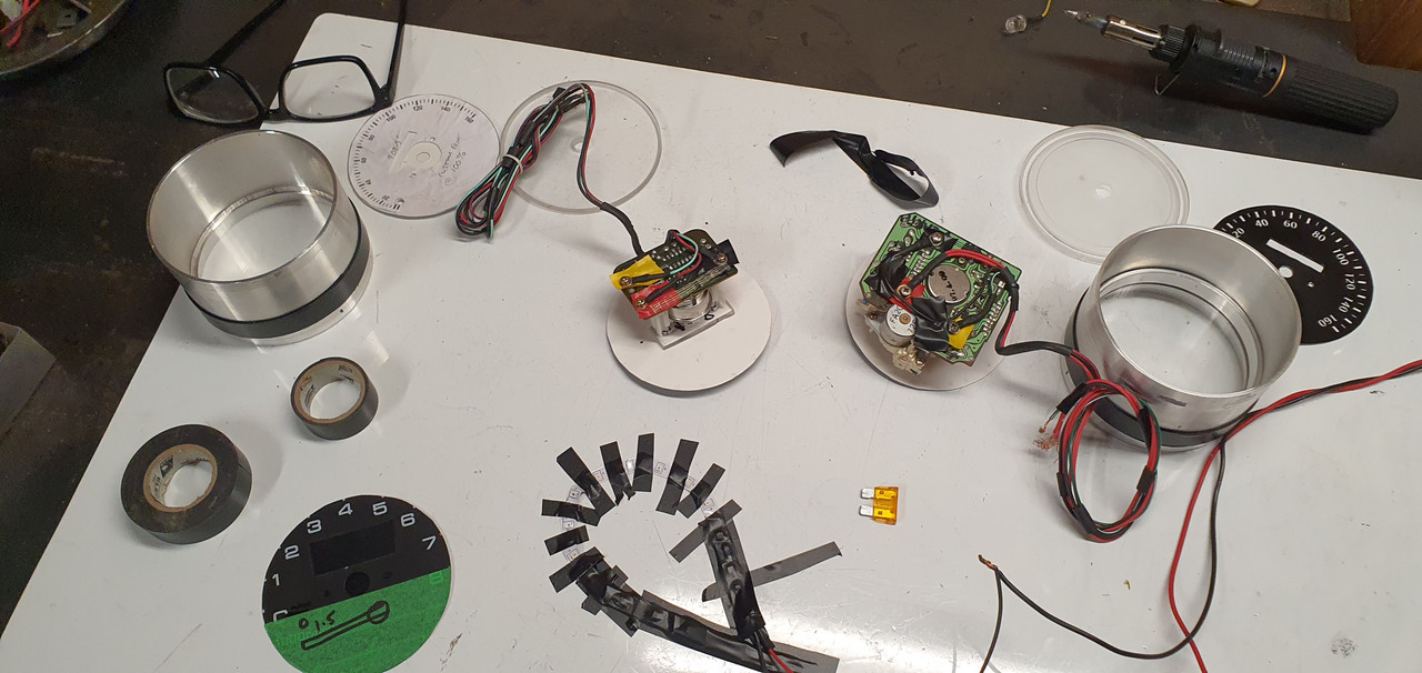
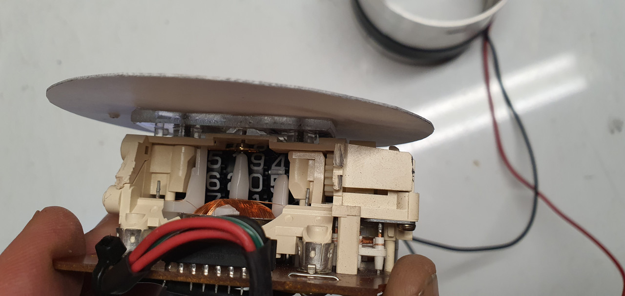
I had to work out how to hold them in position and disperse the light. You can see here the thin bit of molded clear plastic backing from behind the gauge faces had been cut down when I built them.
I cut some more acrylic discs..
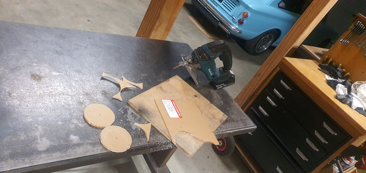
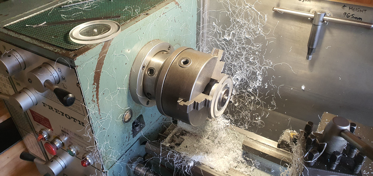
Made lots of mess in the lathe and mill..
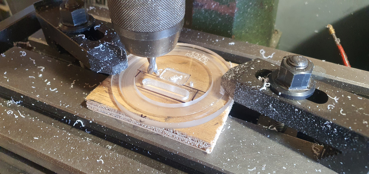
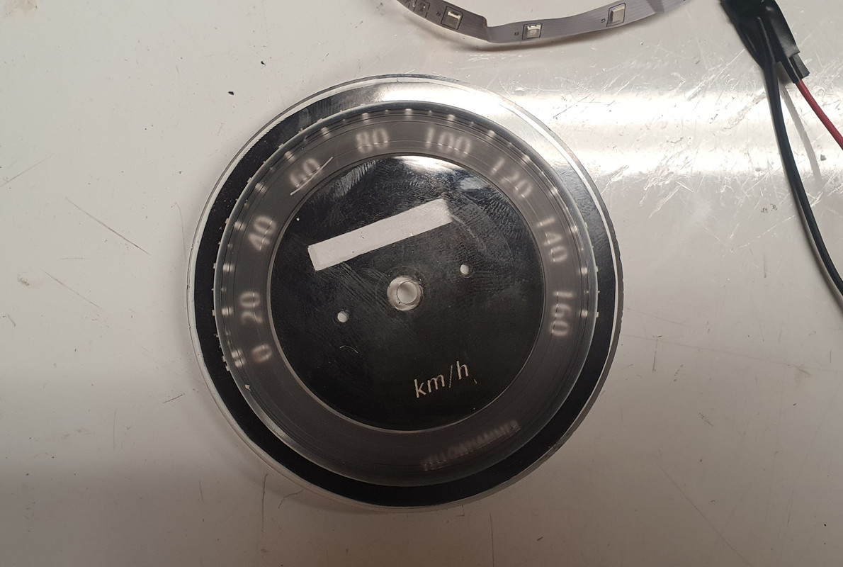
Leds sit in the groove..
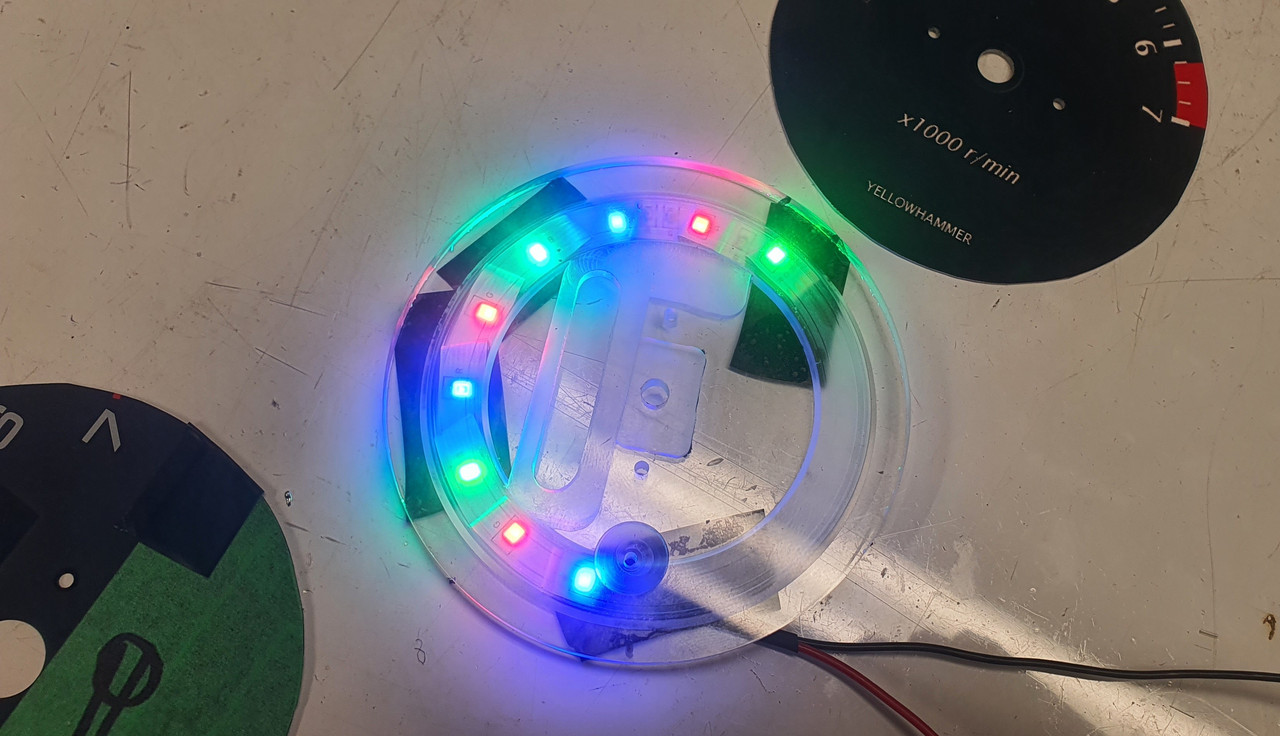
Softens and spreads the light and diverts some light to the pickups on the needle centres.
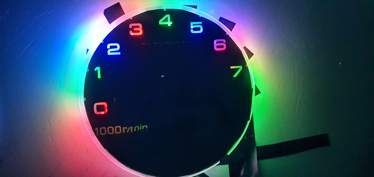
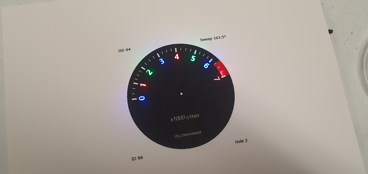
I then printed new faces with a revised, slightly larger, clearer font. I still might change it again in time. Easy and fun to do. Here's the light through the card..
Fitted into the casings..
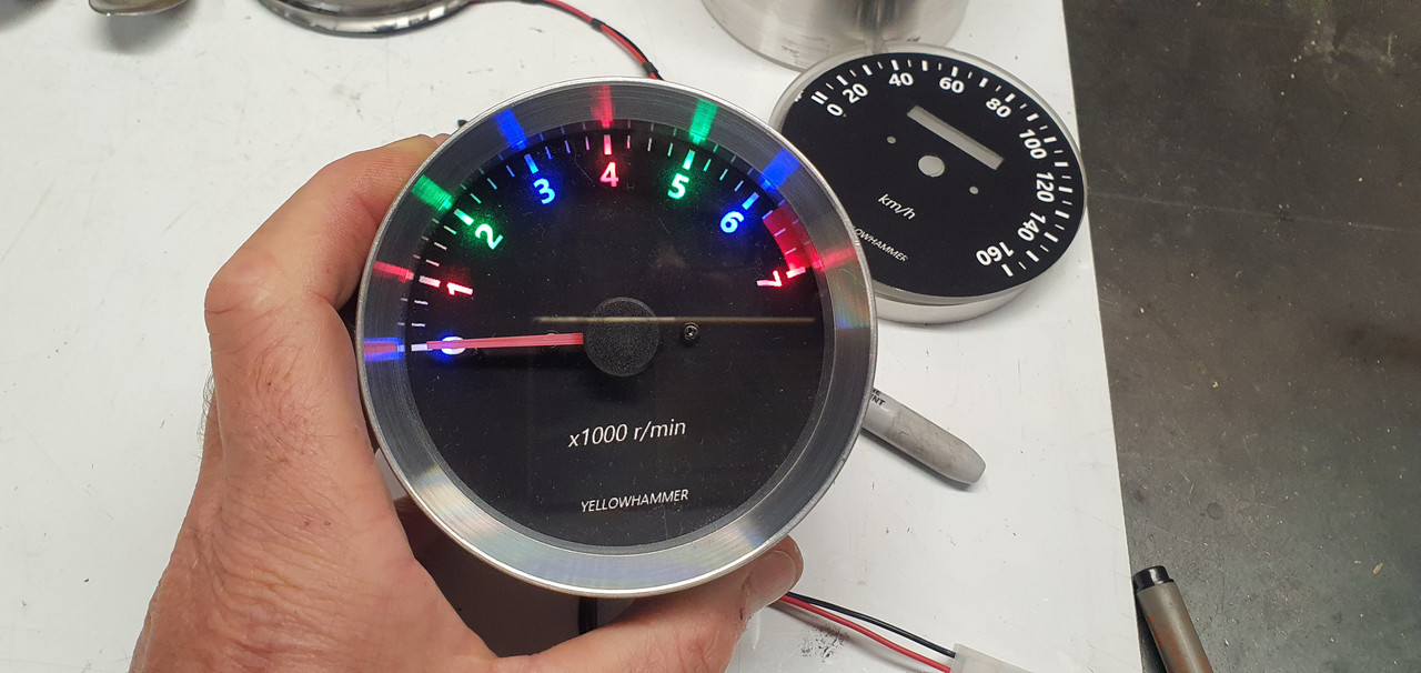
Really happy with that.
Now onto the dash build. I got the long folder out and some thin alloy sheet.
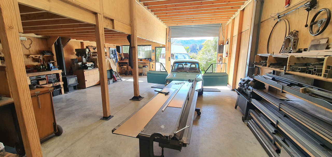
Folded up a basic shape..
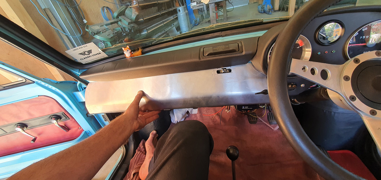
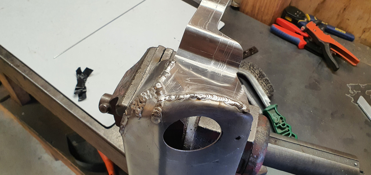
Cut, bent, hammered, welded it to a shape I fancied..
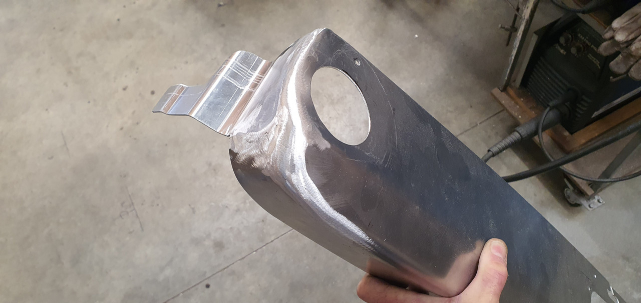
Flap disc and its now smooth..
Screwed some alloy angle to the lip on the bottom of the dash panel..
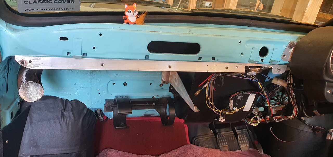
Built in bracing and mounts for a bolt in glove box..
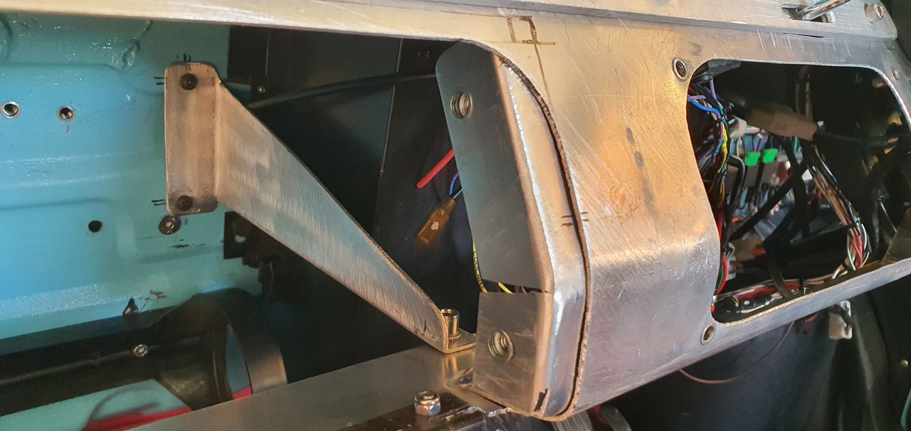
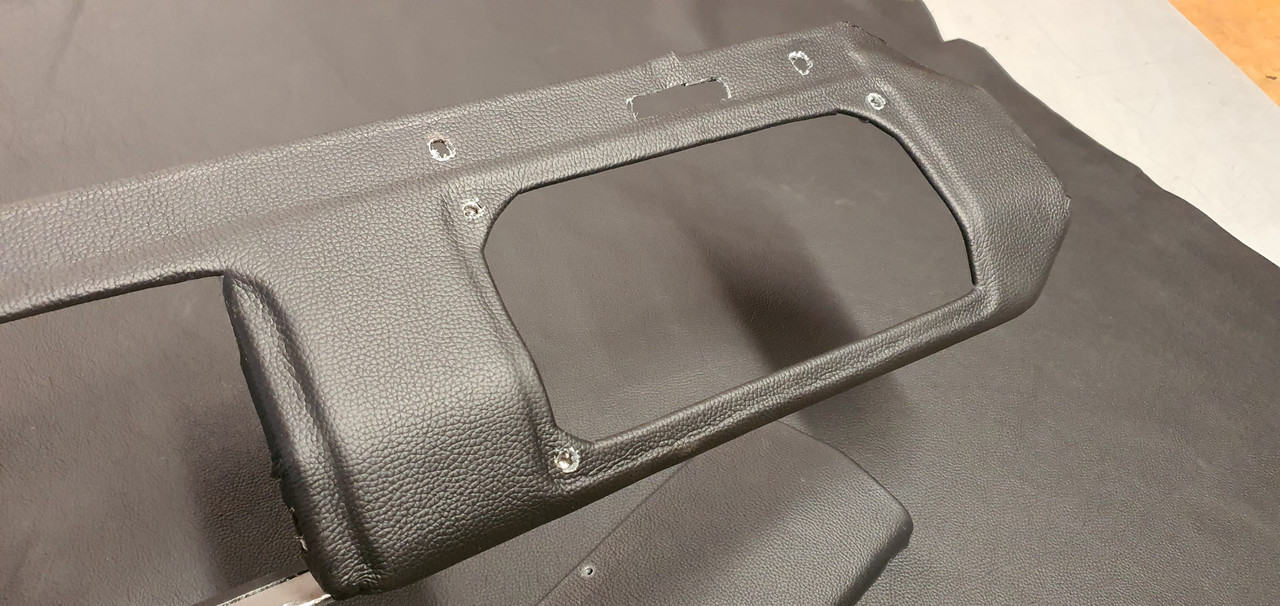
Once I was happy with the alloy structure I rolled out the leather. Lucky I'd bought plenty. I glued on one layer first, carefully cut to provide a stepped relief where needed. Then a second layer followed.
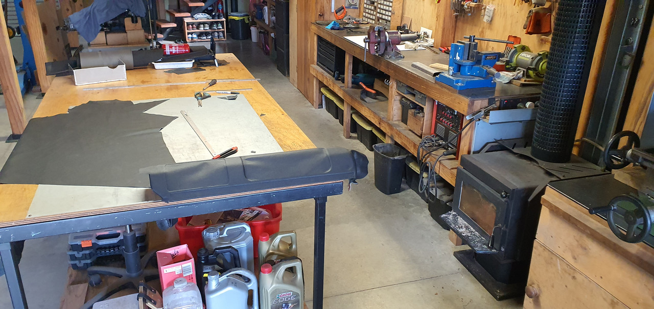
The hardest bit was the lower compound corner. Took some time and needed a cut.
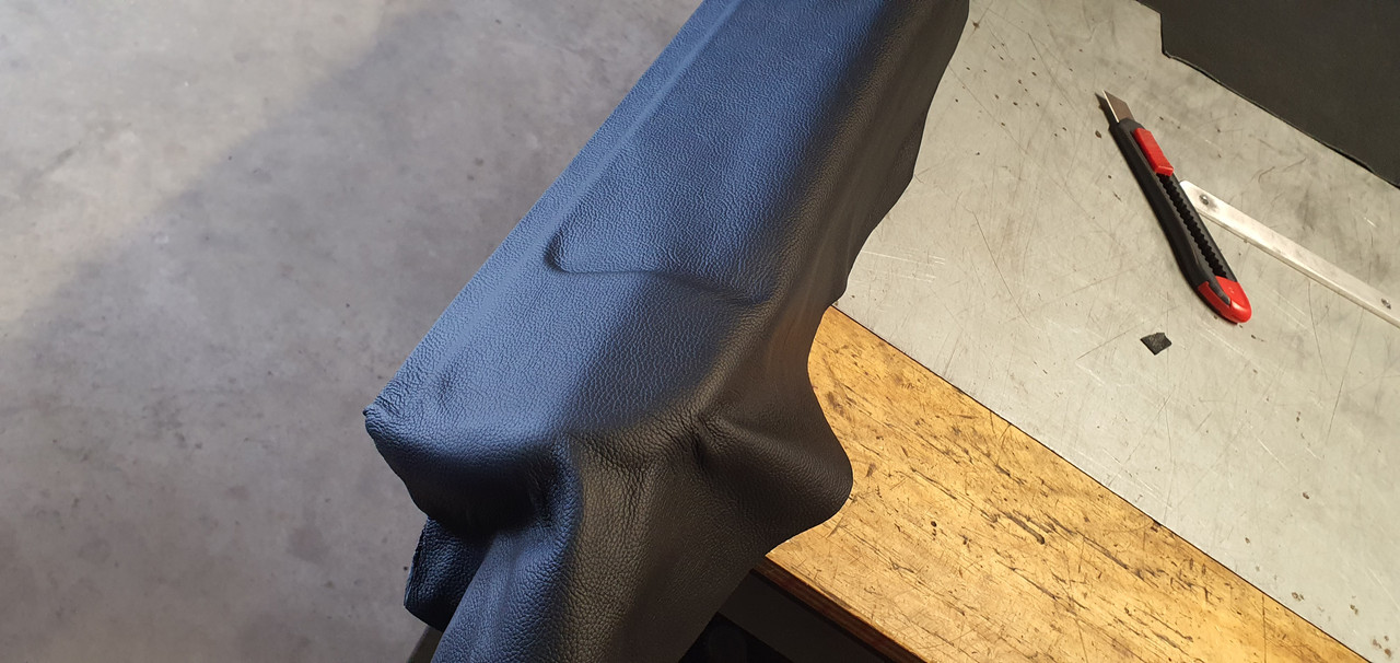
Very happy with the finished dash. Looks neat.
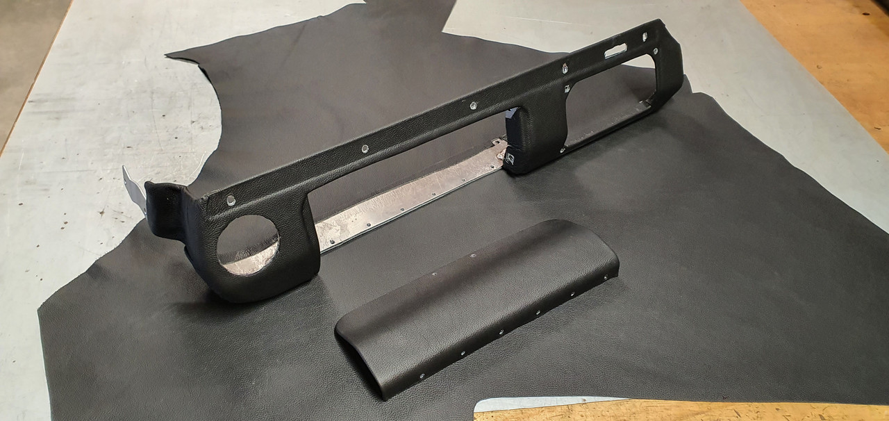
The reliefs are visible
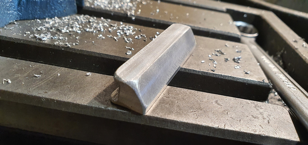
Next up was the glove box edge and handle. I machined up this little handle..
Fits like this..
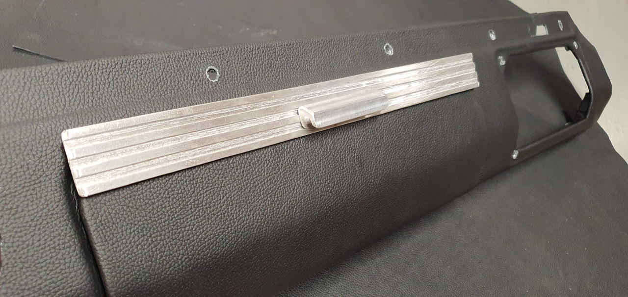
There's a magnet hidden in another alloy strip on the back which clicks against another on a bracket off the dash.
A fellow Imp nutter from Hamilton kindly sent a load of extra Imp switches and a temp gauge down to me and wouldn't even accept money for the postage! Thanks so much John!!
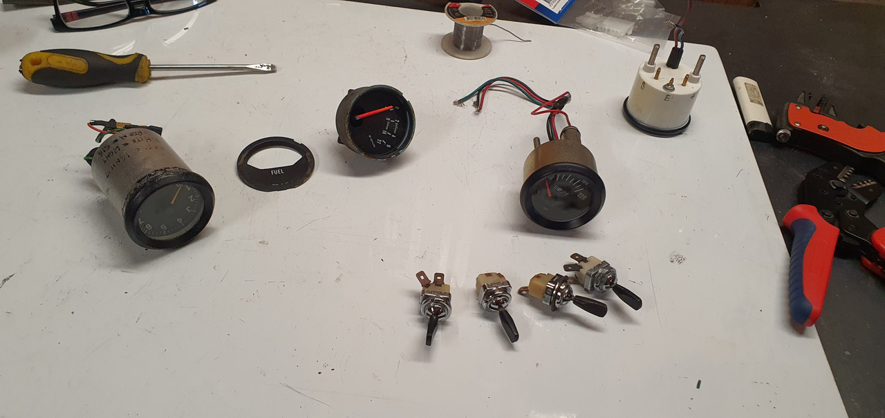
The gauge matches the spare imp fuel gauge but neither of them quite have the look I want so I have ordered another Trisco style fuel gauge to suit my Trisco water temp and oil pressure gauges. Hopefully I'll be able to get the new fuel gauge to work suitably with my Imp fuel level sender - which runs off a 5 volt regulator.
But for now I use what I have. All in place with my switches...
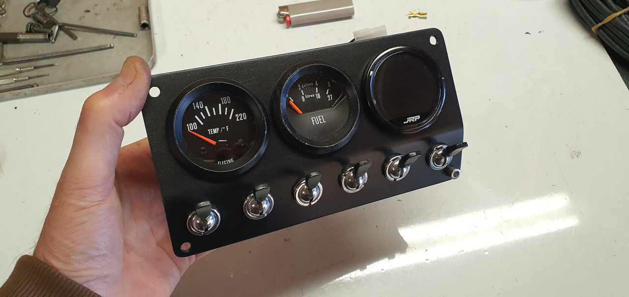
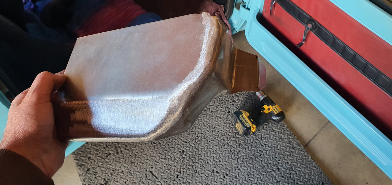
With the left hand side sorted I moved onto the drivers side. Same method. Manipulating some thin alloy, welding (tricky) and flap disc it smooth.
I have to allow for the ugly water pump controller. It has plenty of useful information so I dont want it hidden from view when driving. But it is ugly and not in keeping with the style I want.
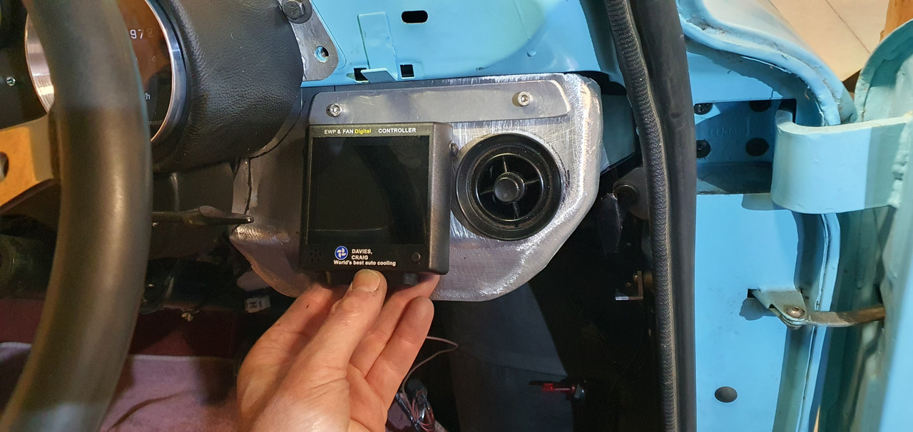
So I cut a hole, added a bolt in bracket to hold it at a suitable angle behind the hole. I will make some sort of slide down cover at a later date to hide the screen when not needed.
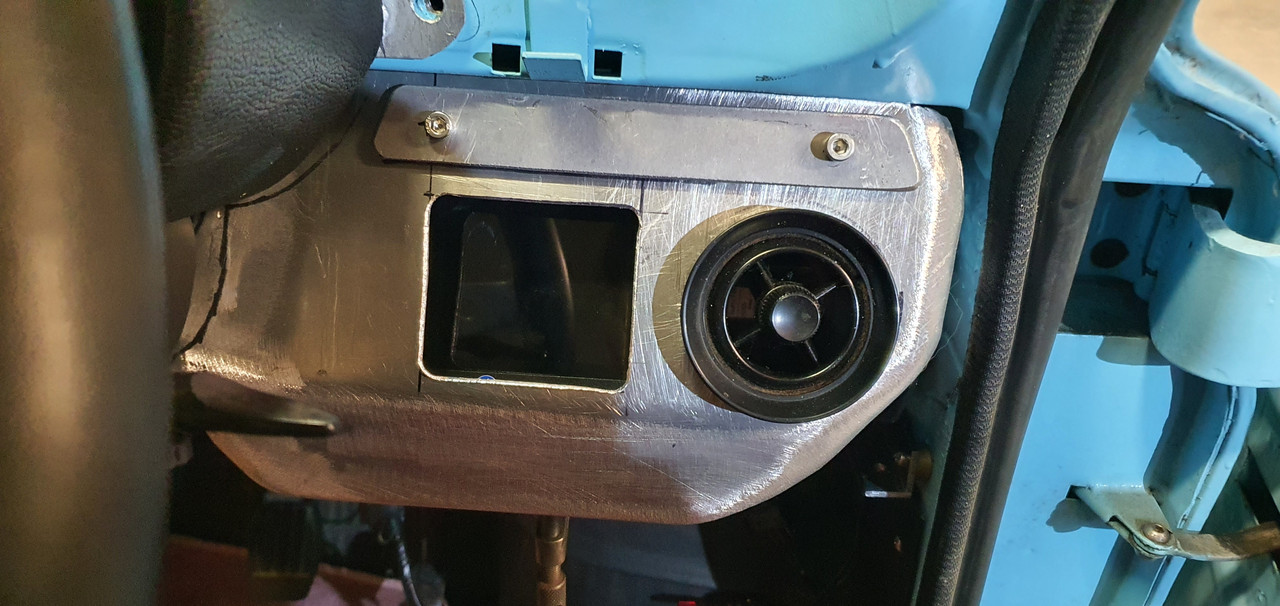
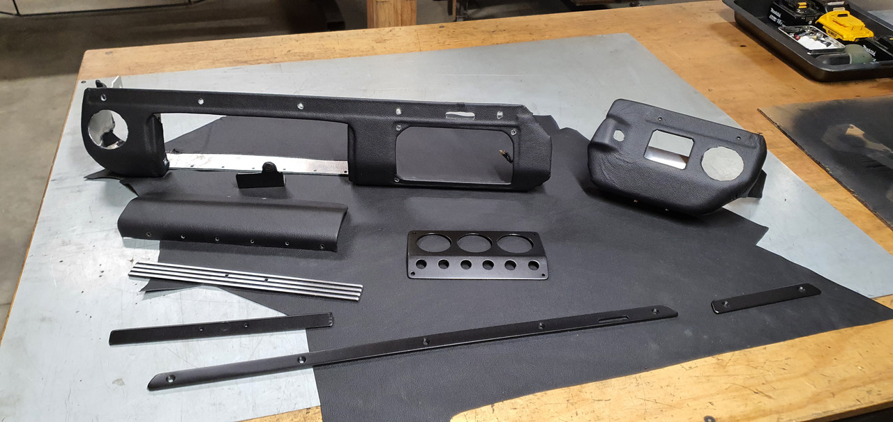
Added an angled face, drilled to suit the ignition key in a suitable usable position. Then covered it all in leather as per the other side. Here are all the bits together, alloy parts painted satin black.
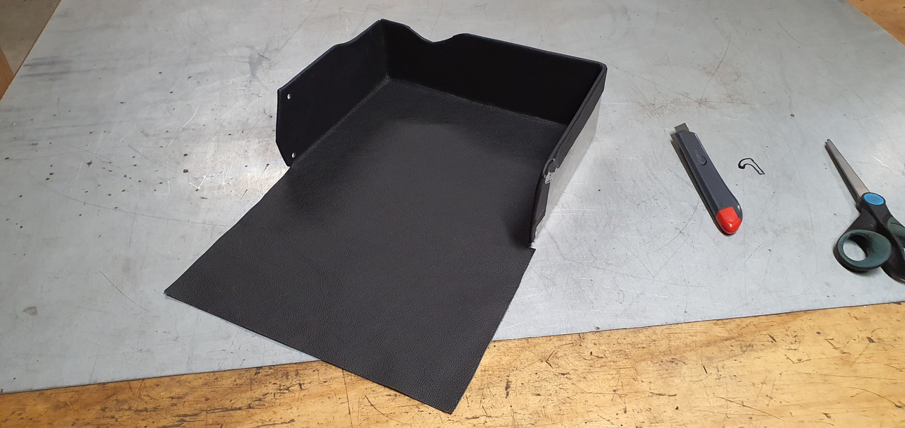
I carefully lined the glove box with leather too because why not..
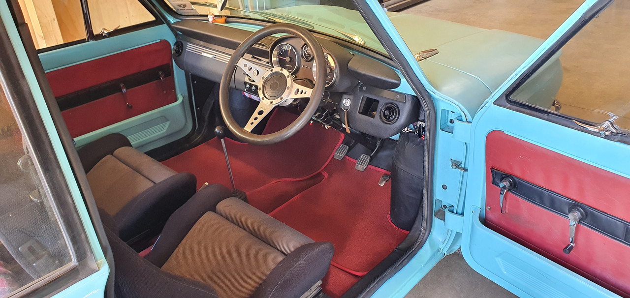
With it all fitted and bolted into place I was able to finish the wiring. I have added extra mini Molex plugs for all the gauges and switches, carefully designing the loom to allow easy simple removal of the units. There are two switches currently wired up but unused - one might be for extra lighting and the other for a suitable under seat bluetooth amp and active subwoofer. I'll be adding some tiny tweeters under the dash out of immediate view.
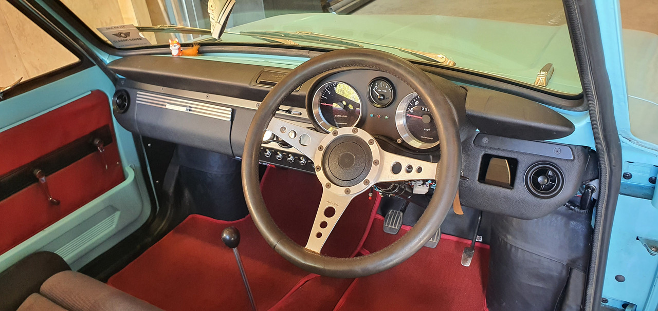
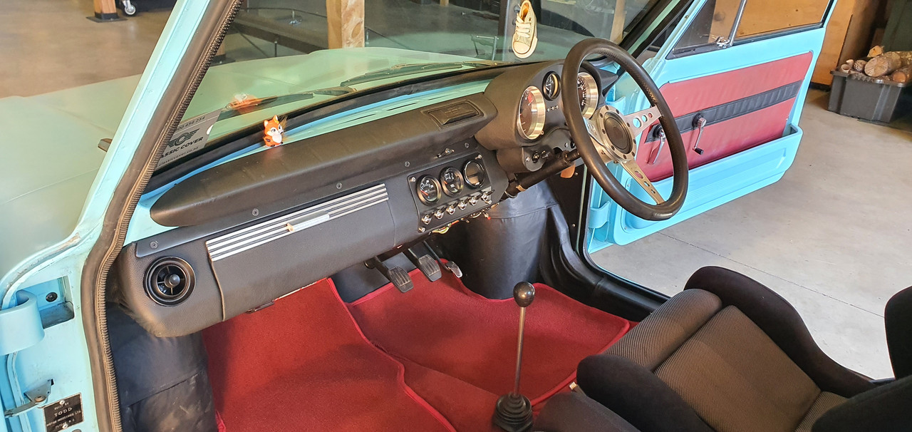
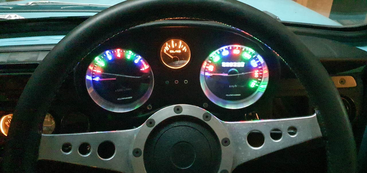
Wiring finished I started the engine. First start in a few months and it fired up beautifully. Rev counter works bang on and reads accurately. Switches all seem to switch as they should. Lights are neat. I took some photos with my phone. I might try for some better pics one evening with suitable light and the big camera.
Overall I'm really stoked with the resulting look and style. The leather work looks great. I have a couple of ideas for possible changes to the colour/style of the alloy trims plus a controller screen cover but will think about it for a bit first.
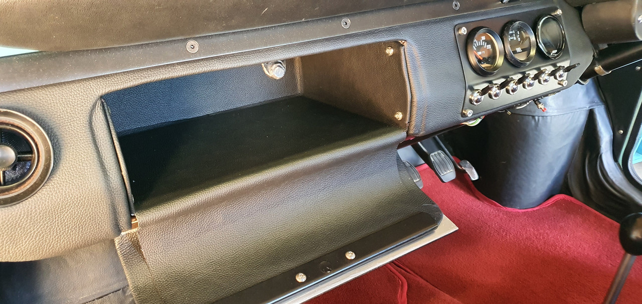
At a later date I will build some partitions along with a built in USB charger into the glovebox..
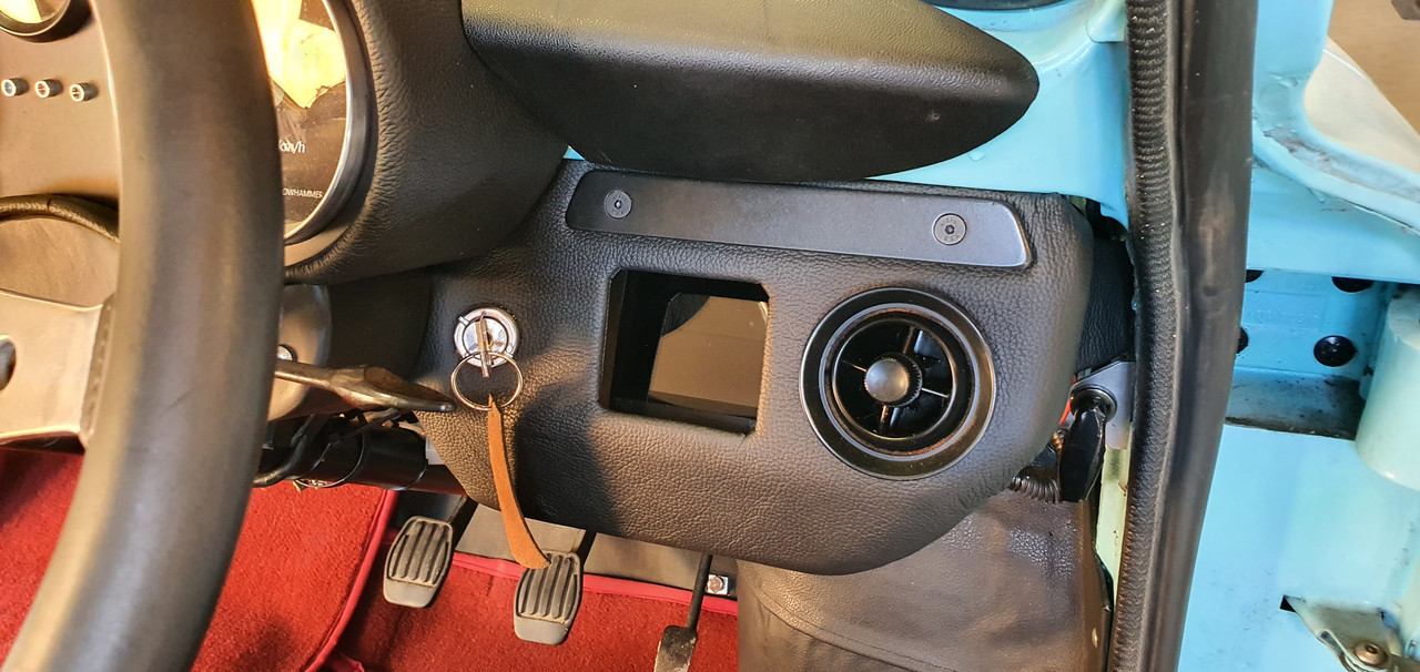
That little controller screen. I have some ideas for this but for now its usable as is.
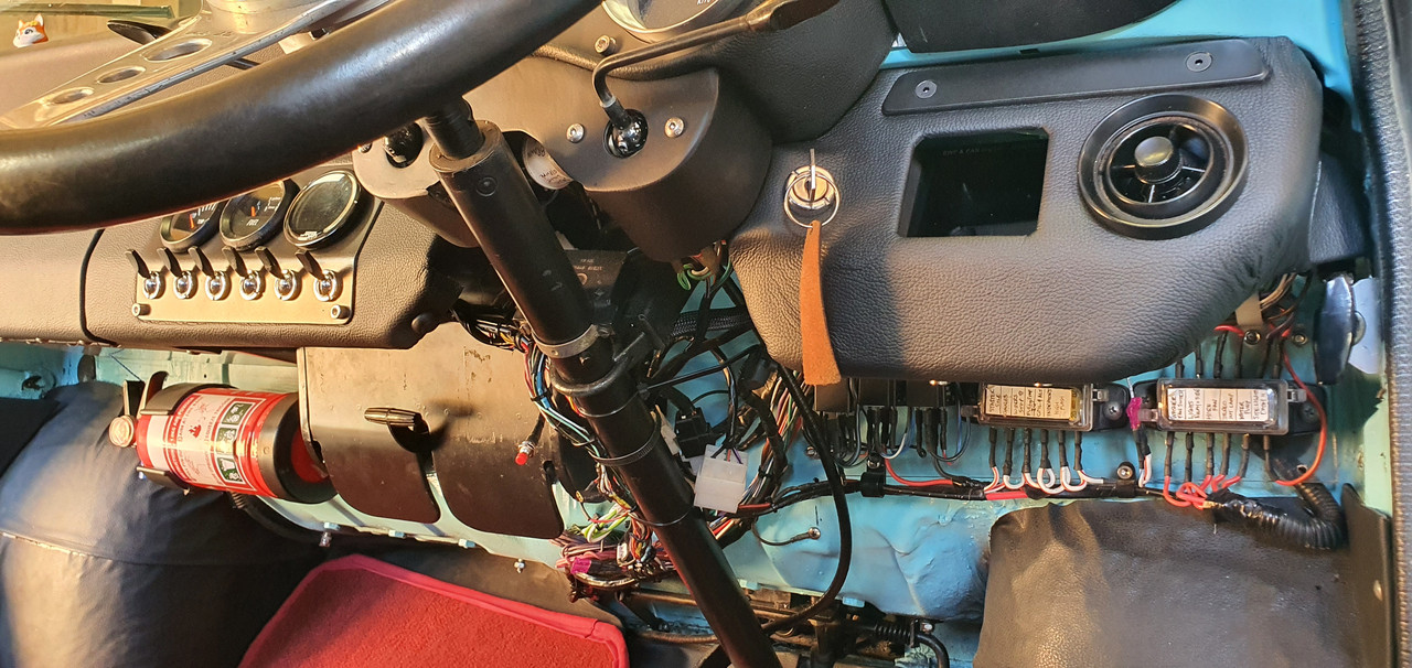
The current fuse and loom hidden from view below. I'm not going to tape it up yet until I have finished adding extras.
The main gauge lights. Bit tricky to get a clear shot on the phone. Needles do light up enough in use.
Phew. What a mission but great fun! Now its back to clearing silt and trees.
Hannah and I have come back from a lovely 6 week holiday, based mainly in Oxford, UK. Mainly cycling and catching up with Hannahs family. We actually got some really good hot, sunny weather too!
While there I contacted a local to Oxford classic Porsche workshop. I took a train 10 miles north to Bicester and walked from there. What was meant to be a short walk turned into a 20km walk in the sun on a 34 degree day thanks to me following out of date Google maps. Lessons learned that day. But I got there in the end and had a tour around the place. Very friendly staff, very tidy. Some fantastic 911s inc I think at least 3 genuine Carrera RS 2.7s. I took many photos...
So that was nice.
They are looking for some staff including a metal worker/engineer for the restoration side. If I was still living in Oxford I probably be there in a flash for the experience.
But back to NZ and we were welcomed with a whole load of slip clearing to do. Our place was one of the many local properties to get completely battered by a massive rain event that happened while Hannah and I were on our flight to the UK. Absolute carnage. I'll do a more detailed update on our bushblock thread.
This is one of our driveway entrances..
The neighbours place got silt through their house..
Fun times. We've got a lot of clearing to do yet including dealing with this huge tree which floated down on a wave of mud and stopped 3 metres shy of our mailbox..
We spent the first week back home fixing our water system which was damaged..
Anyway - that's that. It could have been much worse. Others local to us have lost their houses. Luckily our workshop was fine.
Back to the Imp. My last post was the speedo and rev counter instrument pod build. Next on the list was a new dash which was to include revised switch gear, the other gauges, a pair of Triumph 2500 eyeball vents and an actual glove box rather than this shelf layout as on the passenger side...
and drivers side..
But before making a dash top I needed to sort out lights on my new instruments. I had some rolls of ali express multi coloured led strips.
Stuck them on the bench and had a play..
Cool..
I had to work out how to hold them in position and disperse the light. You can see here the thin bit of molded clear plastic backing from behind the gauge faces had been cut down when I built them.
I cut some more acrylic discs..
Made lots of mess in the lathe and mill..
Leds sit in the groove..
Softens and spreads the light and diverts some light to the pickups on the needle centres.
I then printed new faces with a revised, slightly larger, clearer font. I still might change it again in time. Easy and fun to do. Here's the light through the card..
Fitted into the casings..
Really happy with that.
Now onto the dash build. I got the long folder out and some thin alloy sheet.
Folded up a basic shape..
Cut, bent, hammered, welded it to a shape I fancied..
Flap disc and its now smooth..
Screwed some alloy angle to the lip on the bottom of the dash panel..
Built in bracing and mounts for a bolt in glove box..
Once I was happy with the alloy structure I rolled out the leather. Lucky I'd bought plenty. I glued on one layer first, carefully cut to provide a stepped relief where needed. Then a second layer followed.
The hardest bit was the lower compound corner. Took some time and needed a cut.
Very happy with the finished dash. Looks neat.
The reliefs are visible
Next up was the glove box edge and handle. I machined up this little handle..
Fits like this..
There's a magnet hidden in another alloy strip on the back which clicks against another on a bracket off the dash.
A fellow Imp nutter from Hamilton kindly sent a load of extra Imp switches and a temp gauge down to me and wouldn't even accept money for the postage! Thanks so much John!!
The gauge matches the spare imp fuel gauge but neither of them quite have the look I want so I have ordered another Trisco style fuel gauge to suit my Trisco water temp and oil pressure gauges. Hopefully I'll be able to get the new fuel gauge to work suitably with my Imp fuel level sender - which runs off a 5 volt regulator.
But for now I use what I have. All in place with my switches...
With the left hand side sorted I moved onto the drivers side. Same method. Manipulating some thin alloy, welding (tricky) and flap disc it smooth.
I have to allow for the ugly water pump controller. It has plenty of useful information so I dont want it hidden from view when driving. But it is ugly and not in keeping with the style I want.
So I cut a hole, added a bolt in bracket to hold it at a suitable angle behind the hole. I will make some sort of slide down cover at a later date to hide the screen when not needed.
Added an angled face, drilled to suit the ignition key in a suitable usable position. Then covered it all in leather as per the other side. Here are all the bits together, alloy parts painted satin black.
I carefully lined the glove box with leather too because why not..
With it all fitted and bolted into place I was able to finish the wiring. I have added extra mini Molex plugs for all the gauges and switches, carefully designing the loom to allow easy simple removal of the units. There are two switches currently wired up but unused - one might be for extra lighting and the other for a suitable under seat bluetooth amp and active subwoofer. I'll be adding some tiny tweeters under the dash out of immediate view.
Wiring finished I started the engine. First start in a few months and it fired up beautifully. Rev counter works bang on and reads accurately. Switches all seem to switch as they should. Lights are neat. I took some photos with my phone. I might try for some better pics one evening with suitable light and the big camera.
Overall I'm really stoked with the resulting look and style. The leather work looks great. I have a couple of ideas for possible changes to the colour/style of the alloy trims plus a controller screen cover but will think about it for a bit first.
At a later date I will build some partitions along with a built in USB charger into the glovebox..
That little controller screen. I have some ideas for this but for now its usable as is.
The current fuse and loom hidden from view below. I'm not going to tape it up yet until I have finished adding extras.
The main gauge lights. Bit tricky to get a clear shot on the phone. Needles do light up enough in use.
Phew. What a mission but great fun! Now its back to clearing silt and trees.
-
911hillclimber
- Nurse, I think I need some assistance
- Posts: 20688
- Joined: Mon Mar 10, 2008 6:26 pm
- Location: West Midlands
Re: 1965 Hillman Imp with Honda Goldwing flat 6. Exhaust silencer version 3.0
Knock-out as usual!
Glad you have a hot England.
Hope you sell some of that tree!
Glad you have a hot England.
Hope you sell some of that tree!
73T 911 Coupe, road/hillclimber 3.2L
Lola t 492 / 3.2 hillclimb racer
Boxster 987 Gen II 2.9
Lola t 492 / 3.2 hillclimb racer
Boxster 987 Gen II 2.9
-
yoeddynz
- DDK addict
- Posts: 135
- Joined: Wed Feb 01, 2023 9:02 am
Re: 1965 Hillman Imp with Honda Goldwing flat 6. Exhaust silencer version 3.0
Maybe I could build a flintstones type car from the tree? 
-
stevenery
- DDK addict
- Posts: 103
- Joined: Tue Jul 20, 2010 6:31 pm
- Location: Oxford
Re: 1965 Hillman Imp with Honda Goldwing flat 6. Exhaust silencer version 3.0
Nice to read as ever, Alex! There is Wrightune in Wallingford - run by an old friend of Dan and Jon. Jon took his kids for a look around which they enjoyed.
Hope to see a Porsche project some day. Imagine the engine possibilities for this!
https://www.trademe.co.nz/a/motors/cars ... 5477153557
Hope to see a Porsche project some day. Imagine the engine possibilities for this!
https://www.trademe.co.nz/a/motors/cars ... 5477153557
-
yoeddynz
- DDK addict
- Posts: 135
- Joined: Wed Feb 01, 2023 9:02 am
Re: 1965 Hillman Imp with Honda Goldwing flat 6. Exhaust silencer version 3.0
Last week this lovely thing here...
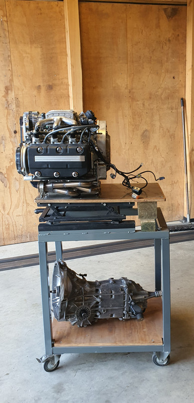
..got replaced with this old lump.. (photo taken while bleeding the cooling system)

I wanted to give the flat six a little look over, check some things and sort out a small oil leak that in retrospect I should have just ignored because it turned into a mini ball ache. I should just accept that any engine fitted into a British car is destined to leak oil to some extent.
I started operation leak fix by sliding the engine off the engine stand onto the big table, glad to have made the table, the benches and the stand all the same height, then standing the engine on its end. I popped the sump off and started pulling the oil system pipework apart..
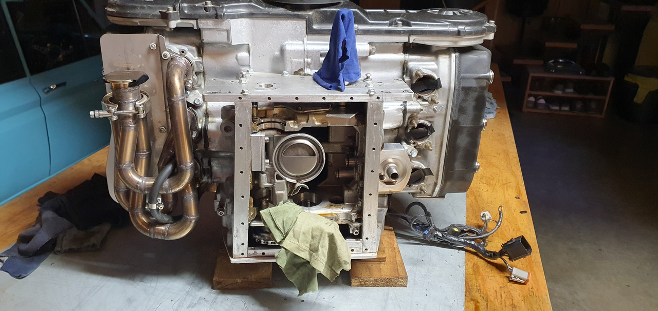
The aim was to stop the oil that was seeping out between the oil filter pedestal and the crankcase. I had previously tried sealing it externally with some gloop but it was too awkward to get in there properly. You can see the residue in this shot..
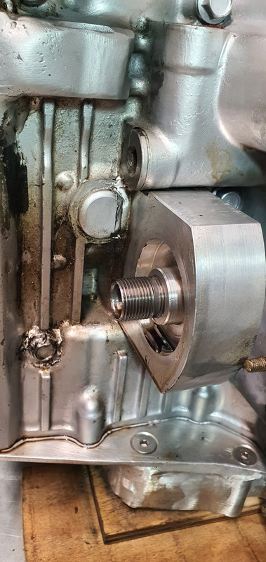
Oil creeping through between the pedestal pipes and weeping through the card gasket I'd fitted.
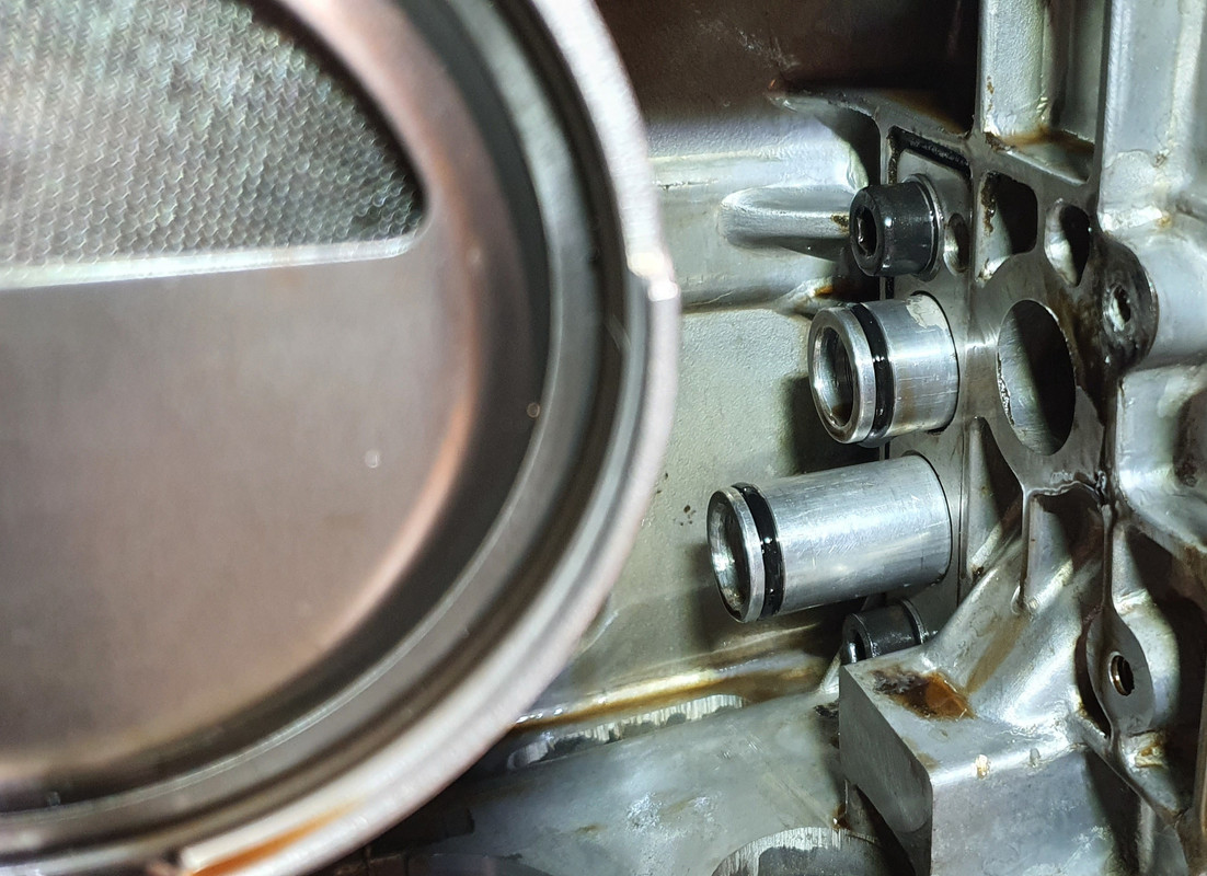
But i discovered I couldn't remove the pedestal fully without removing one of the exhaust studs and there was no way that exhaust stud wanted to come out easily. I tried a bit of heat, cooling the stud with spray, two nuts, vice grips. I really didn't want to risk damaging it. Luckily I was able to pull the pedestal out away from the case enough to squirt sealant into the gap after a thorough cleaning. Smeared the gloop in neatly with my fingers, pulled to pedestal up tight with its bolts. Happy it was now sealed up I reassembled then painted the area..
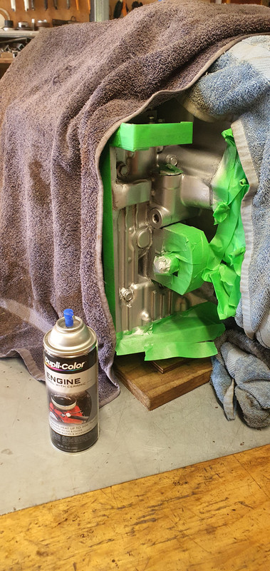
All the various gubbins back in place..
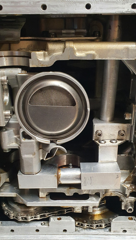
I like this shot..
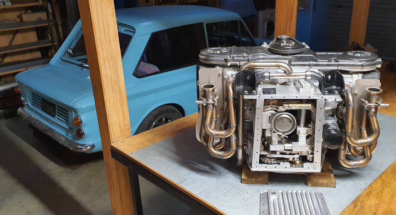
While the engine is out I checked the oil pump drive chains. They seem fine and no slacker than when fitted so no need to adjust tensions.
Whilst checking them and looking over the system I worked out a better (simpler) way I could have made the system that would use just the one chain. Future tinkering if I ever needed to but for now it works so I'll keep running it and check it every so often.
So while this has been happening the Datsun A12 is back in place. I had to fix another hole in the old muffler I'd built for the Datsun. Its pretty rotten in places.
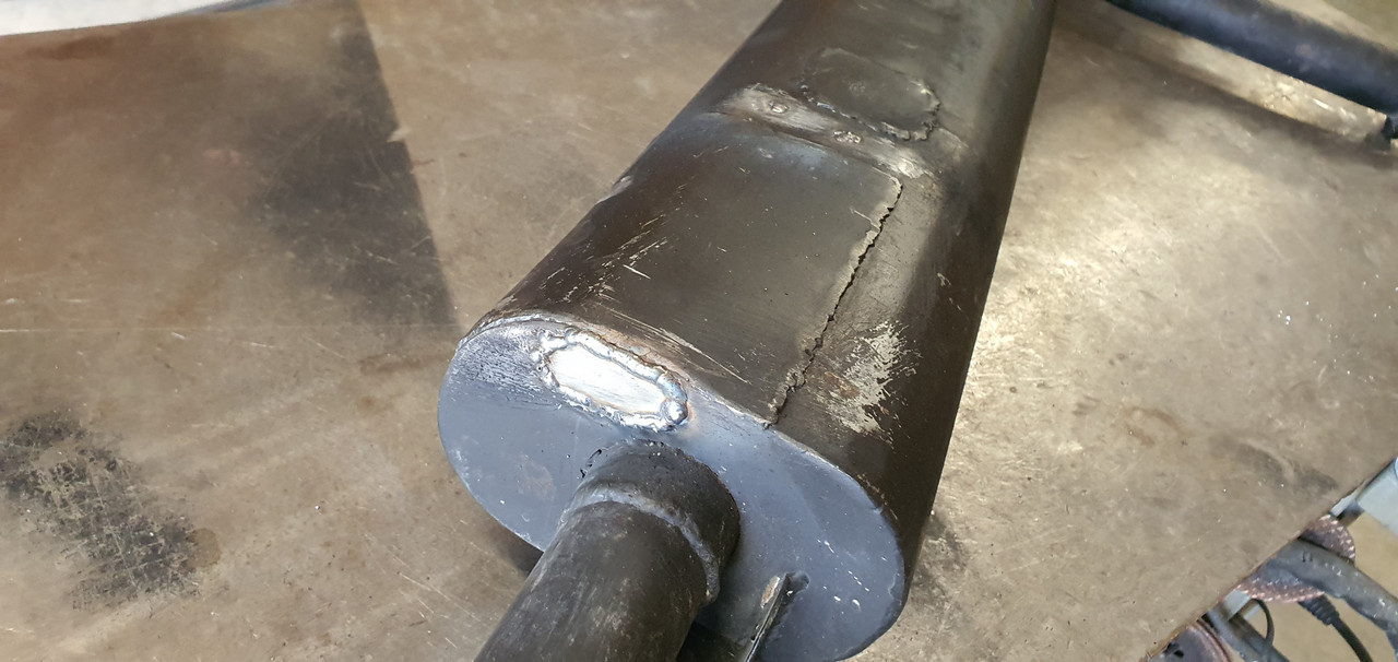
The temp gauge reads too high - I suspect the only way its changed is from different wiring in the new dash layout due to larger wiring having less resistance. But there was no change in temps shown with the flat six. Very weird. Anyway, in order to stop the Datsun temp reading 120 C I added a variable resister inline on the sensor wire..
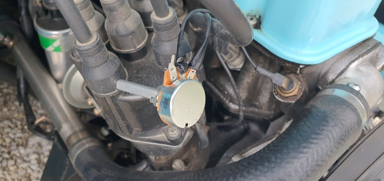
Adjusted that until the temp was where I guessed it should be, measured the resistance and looked through my stash of bits..
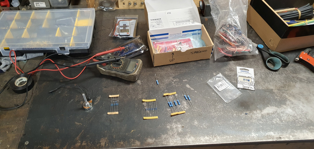
Found a resister close enough..
Its now fitted with teminals and covered in heat shrink. While on the subject of gauges I had the fuel gauge I'd ordered from Ali express ($15 delivered). As a bonus the delivery folks involved squashed the box and added patina to the lovely black bezel. Ho hum. But at least I have a gauge that matches the Trisco temp gauge (poor mans VDO)..
I bought this gauge knowing full well that it most likely wont work accurately with my Imp fuel tank sender. I wired it up on the bench with a spare sender and to my surprise it actually reads bang on ..

Only issue is its not a damped system. The gauge responds instantly so the needle does flutter about on rough roads but one only needs to drive along on a straight smooth surface for a few seconds to get an accurate reading.
I rummaged through my extensive supply of various dash bulbs, many of which are Nissan K11 items. Found some green ones for this both this and the temp gauge for a nicer glow. I'll change the one in the oil pressure gauge to match. I have also had a load more leds with controllers turn up from Ali. I'll be having a play with some under dash floor lighting and some lighting in the engine bay.
When I read did all the wiring involved with the new dashboard layout I added in a spare plug to suit a spare Toyota speedo hall sensor just like what I'm using on the Subaru transmission. Earlier in the year I had machined up an alloy adaptor with two different threads. One end to suit the sensor, the other to suit the Imp speedo cable. It all tucks away up under the dash. With the Datsun installed I was able to try it..
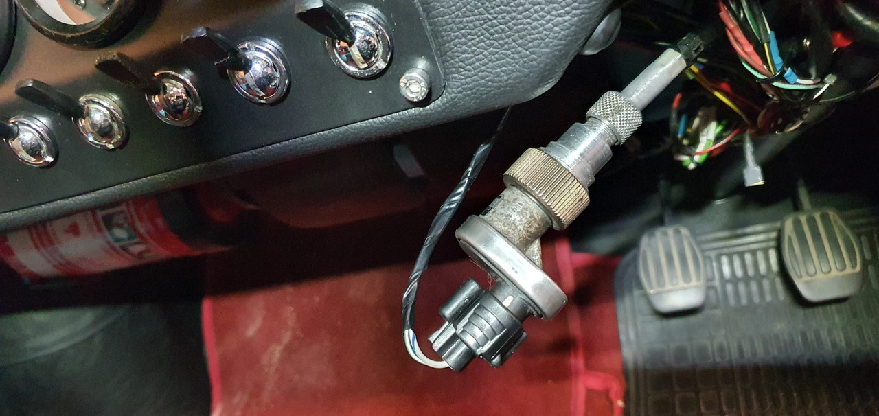
The speedo cable on Imps is driven off the passenger front wheel so spins at road speed. I had not bothered to check what the ratio of the speedo output on the Subaru box was relative to road wheel speed. I didn't even have any idea what it could be. I just took the imp for a drive prepared for some completely errant reading, either way to slow or far too fast.
However the gauge gods must really have been in a good mood with me recently because the speedo reads almost bang on. Wow. This has saved me extra bother because if it was completely inaccurate I was prepared to swap back in the original mechanical strip speedo for Datsun duties. Now the swap between both engines is even easier.
I've driven the imp about in the last few days and I'm always really impressed with how well the little Datsun engine goes. Its so neat. Its a torquey little thing. Although not even close to the smoothness of the six, or anywhere as quick, it still makes for a great daily drive. But I'm really looking forward to going back to the hopefully leak free Honda.. fingers crossed.
..got replaced with this old lump.. (photo taken while bleeding the cooling system)
I wanted to give the flat six a little look over, check some things and sort out a small oil leak that in retrospect I should have just ignored because it turned into a mini ball ache. I should just accept that any engine fitted into a British car is destined to leak oil to some extent.
I started operation leak fix by sliding the engine off the engine stand onto the big table, glad to have made the table, the benches and the stand all the same height, then standing the engine on its end. I popped the sump off and started pulling the oil system pipework apart..
The aim was to stop the oil that was seeping out between the oil filter pedestal and the crankcase. I had previously tried sealing it externally with some gloop but it was too awkward to get in there properly. You can see the residue in this shot..
Oil creeping through between the pedestal pipes and weeping through the card gasket I'd fitted.
But i discovered I couldn't remove the pedestal fully without removing one of the exhaust studs and there was no way that exhaust stud wanted to come out easily. I tried a bit of heat, cooling the stud with spray, two nuts, vice grips. I really didn't want to risk damaging it. Luckily I was able to pull the pedestal out away from the case enough to squirt sealant into the gap after a thorough cleaning. Smeared the gloop in neatly with my fingers, pulled to pedestal up tight with its bolts. Happy it was now sealed up I reassembled then painted the area..
All the various gubbins back in place..
I like this shot..
While the engine is out I checked the oil pump drive chains. They seem fine and no slacker than when fitted so no need to adjust tensions.
Whilst checking them and looking over the system I worked out a better (simpler) way I could have made the system that would use just the one chain. Future tinkering if I ever needed to but for now it works so I'll keep running it and check it every so often.
So while this has been happening the Datsun A12 is back in place. I had to fix another hole in the old muffler I'd built for the Datsun. Its pretty rotten in places.
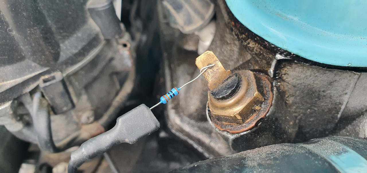
The temp gauge reads too high - I suspect the only way its changed is from different wiring in the new dash layout due to larger wiring having less resistance. But there was no change in temps shown with the flat six. Very weird. Anyway, in order to stop the Datsun temp reading 120 C I added a variable resister inline on the sensor wire..
Adjusted that until the temp was where I guessed it should be, measured the resistance and looked through my stash of bits..
Found a resister close enough..
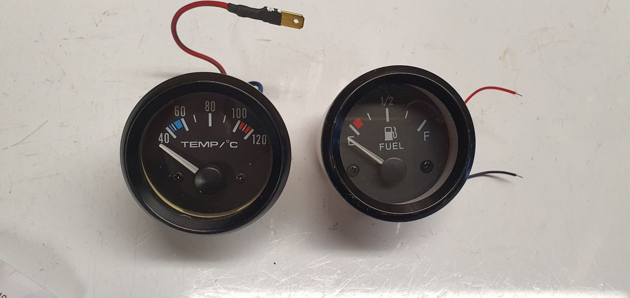
Its now fitted with teminals and covered in heat shrink. While on the subject of gauges I had the fuel gauge I'd ordered from Ali express ($15 delivered). As a bonus the delivery folks involved squashed the box and added patina to the lovely black bezel. Ho hum. But at least I have a gauge that matches the Trisco temp gauge (poor mans VDO)..
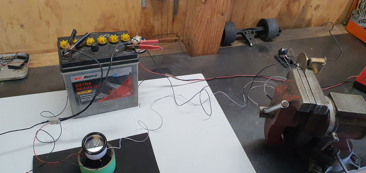
I bought this gauge knowing full well that it most likely wont work accurately with my Imp fuel tank sender. I wired it up on the bench with a spare sender and to my surprise it actually reads bang on ..
Only issue is its not a damped system. The gauge responds instantly so the needle does flutter about on rough roads but one only needs to drive along on a straight smooth surface for a few seconds to get an accurate reading.
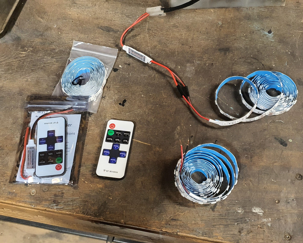
I rummaged through my extensive supply of various dash bulbs, many of which are Nissan K11 items. Found some green ones for this both this and the temp gauge for a nicer glow. I'll change the one in the oil pressure gauge to match. I have also had a load more leds with controllers turn up from Ali. I'll be having a play with some under dash floor lighting and some lighting in the engine bay.
When I read did all the wiring involved with the new dashboard layout I added in a spare plug to suit a spare Toyota speedo hall sensor just like what I'm using on the Subaru transmission. Earlier in the year I had machined up an alloy adaptor with two different threads. One end to suit the sensor, the other to suit the Imp speedo cable. It all tucks away up under the dash. With the Datsun installed I was able to try it..
The speedo cable on Imps is driven off the passenger front wheel so spins at road speed. I had not bothered to check what the ratio of the speedo output on the Subaru box was relative to road wheel speed. I didn't even have any idea what it could be. I just took the imp for a drive prepared for some completely errant reading, either way to slow or far too fast.
However the gauge gods must really have been in a good mood with me recently because the speedo reads almost bang on. Wow. This has saved me extra bother because if it was completely inaccurate I was prepared to swap back in the original mechanical strip speedo for Datsun duties. Now the swap between both engines is even easier.
I've driven the imp about in the last few days and I'm always really impressed with how well the little Datsun engine goes. Its so neat. Its a torquey little thing. Although not even close to the smoothness of the six, or anywhere as quick, it still makes for a great daily drive. But I'm really looking forward to going back to the hopefully leak free Honda.. fingers crossed.