1965 Hillman Imp soon with flat six from a Honda

The place to post images of your other cars.

Moderator: Bootsy

yoeddynz
DDK Fanatic
Posts: 55
Joined: Wed Feb 01, 2023 9:02 am

Re: 1965 Hillman Imp soon with flat six from a Honda

Post by yoeddynz »

Well after the last novel length wall of text I'll try to keep this update shorter otherwise I'll never finish the thing. Lots of little jobs starting to pop up on my 'to do' list.

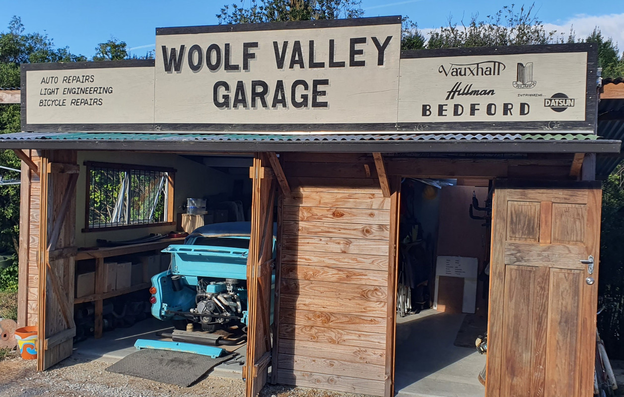
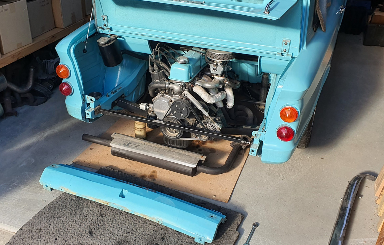
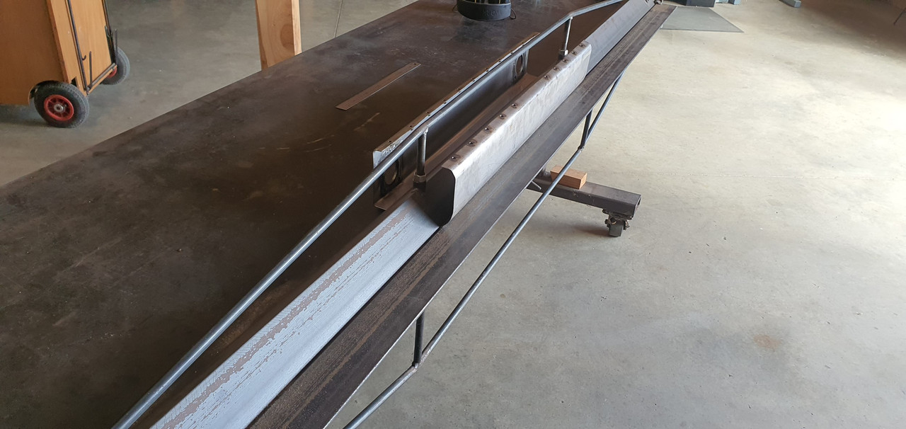
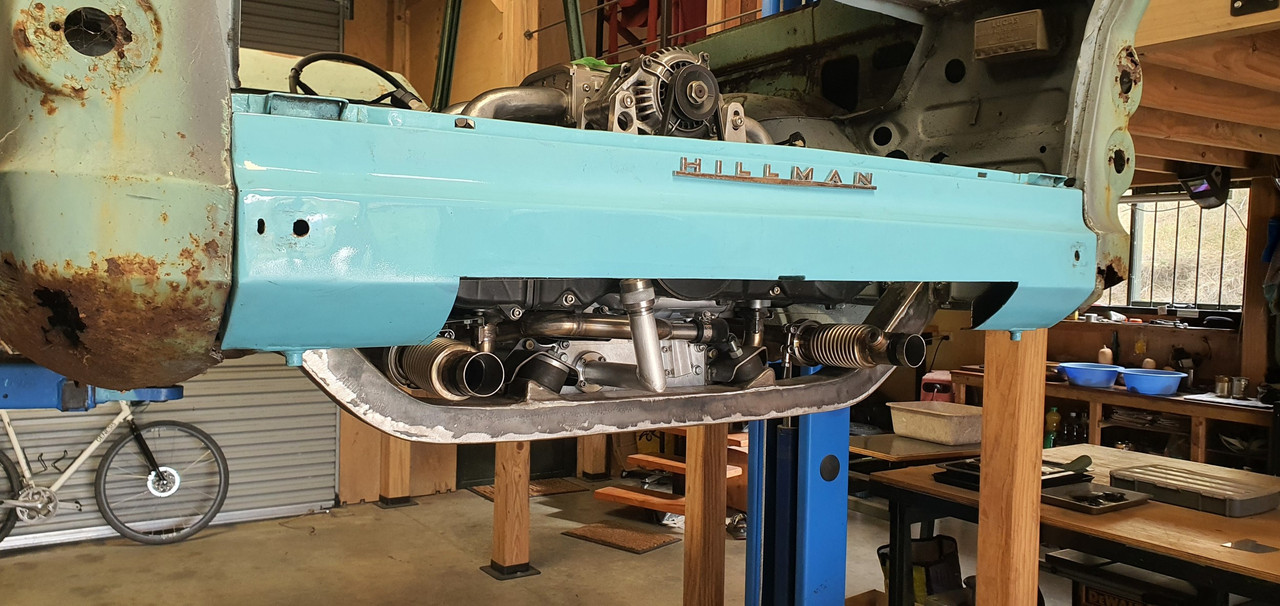
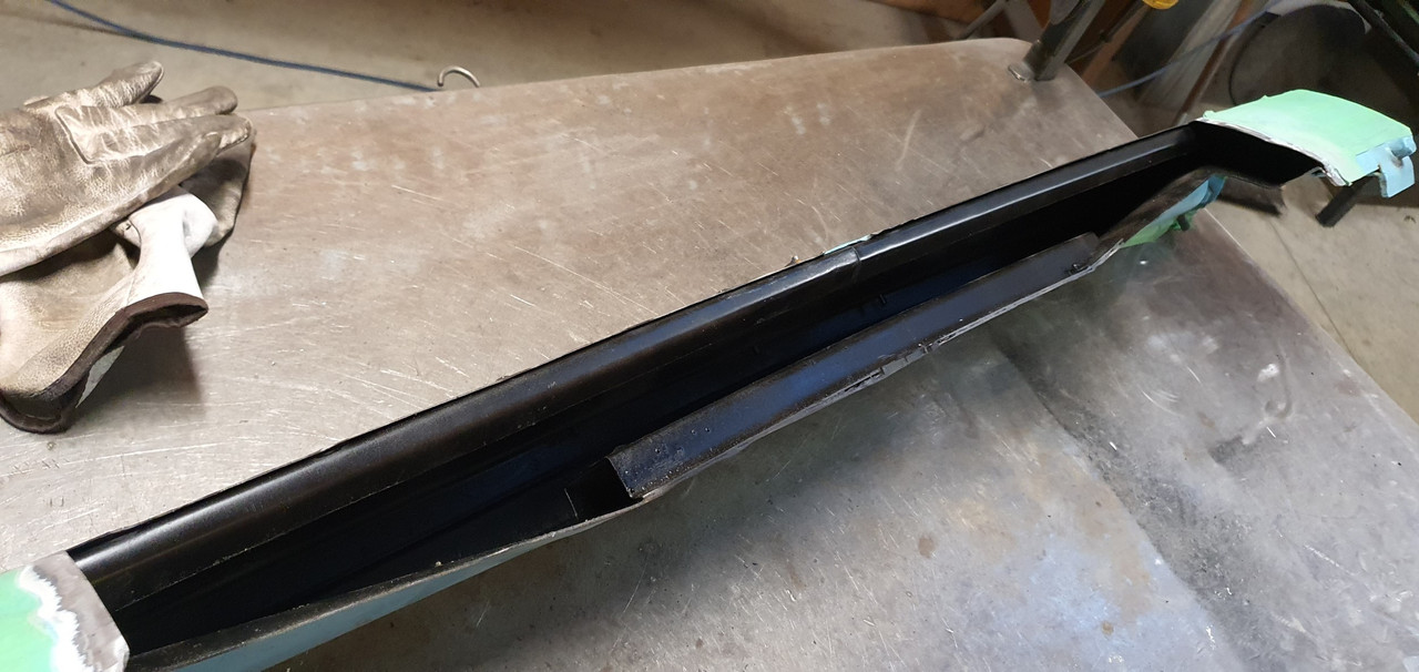
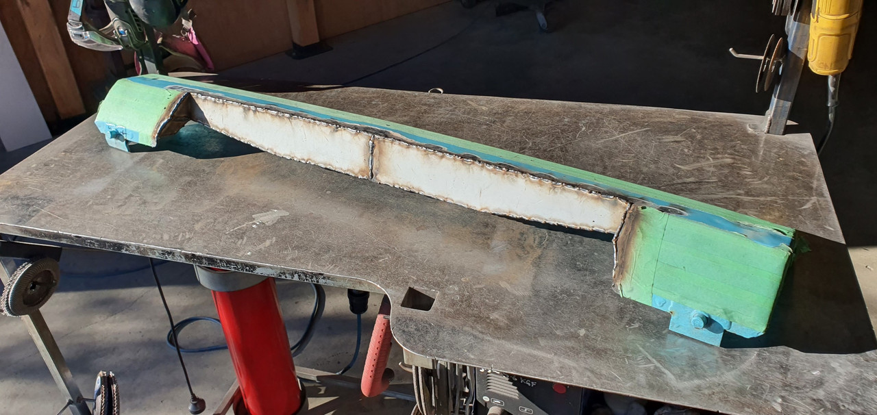
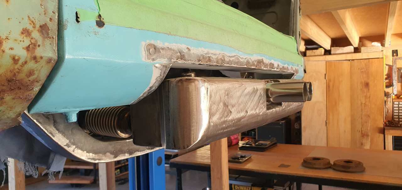
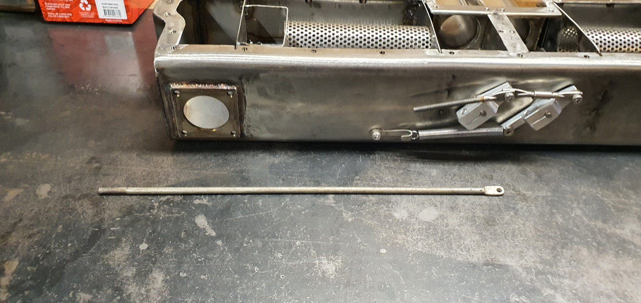
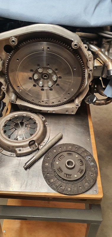
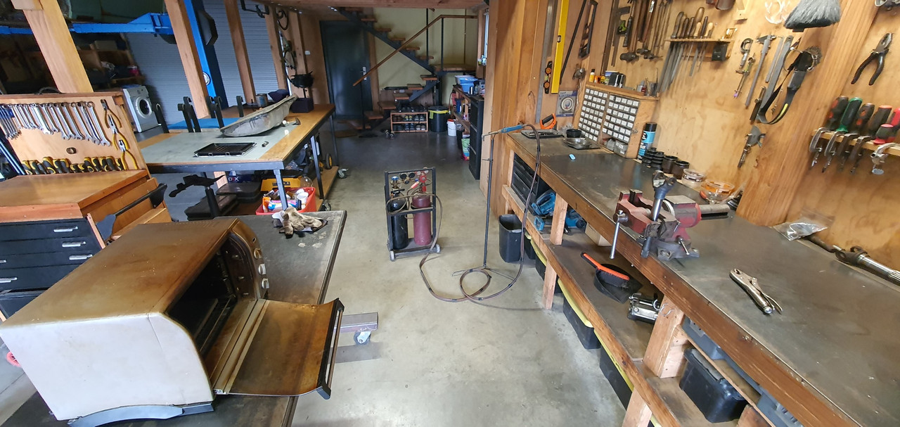
Driveshafts. Connecting the scooby shafts to the imp axles.

Image

A job I wasn't sure which direction I'd take as there's so many different ideas out there on the nerdnet showing 'the best' way to join shafts.

First thing I did was to double check the suspension travel allowed by the stock shock absorbers and then use those datum points to work out if there was any growth in the length of shaft required as the wheel moves through it path up and down. There was minimal amount, like maybe 5mm at the very most. I guessed as much because the stock Imp driveshaft doughnuts don't allow for much sideways travel.

I then cut one of my 22mm scooby shafts down in length so I could work out the lengths required with the CV joint in place. This move I soon regretted.

Image

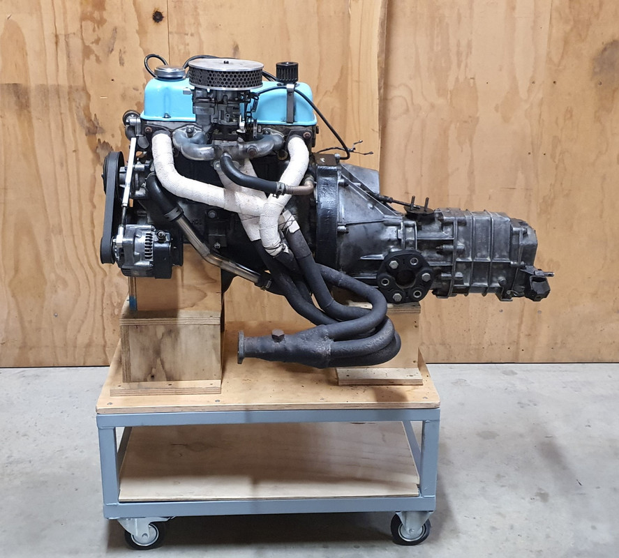
I was allowing for plenty of plunge into the CV joints to make sure the whole joint could be removed from the box stub axle with the box pushed sideways when removing the transmission. I was happy with the length and then decided to go visit a local hotrod builder friend for some advise. He's well known about for his many many full scratch builds and has done heaps of driveshafts in his time (a fellow machinist by trade too)

I showed him the two ways I was considering doing the join. He showed me a better way.

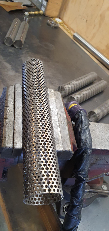
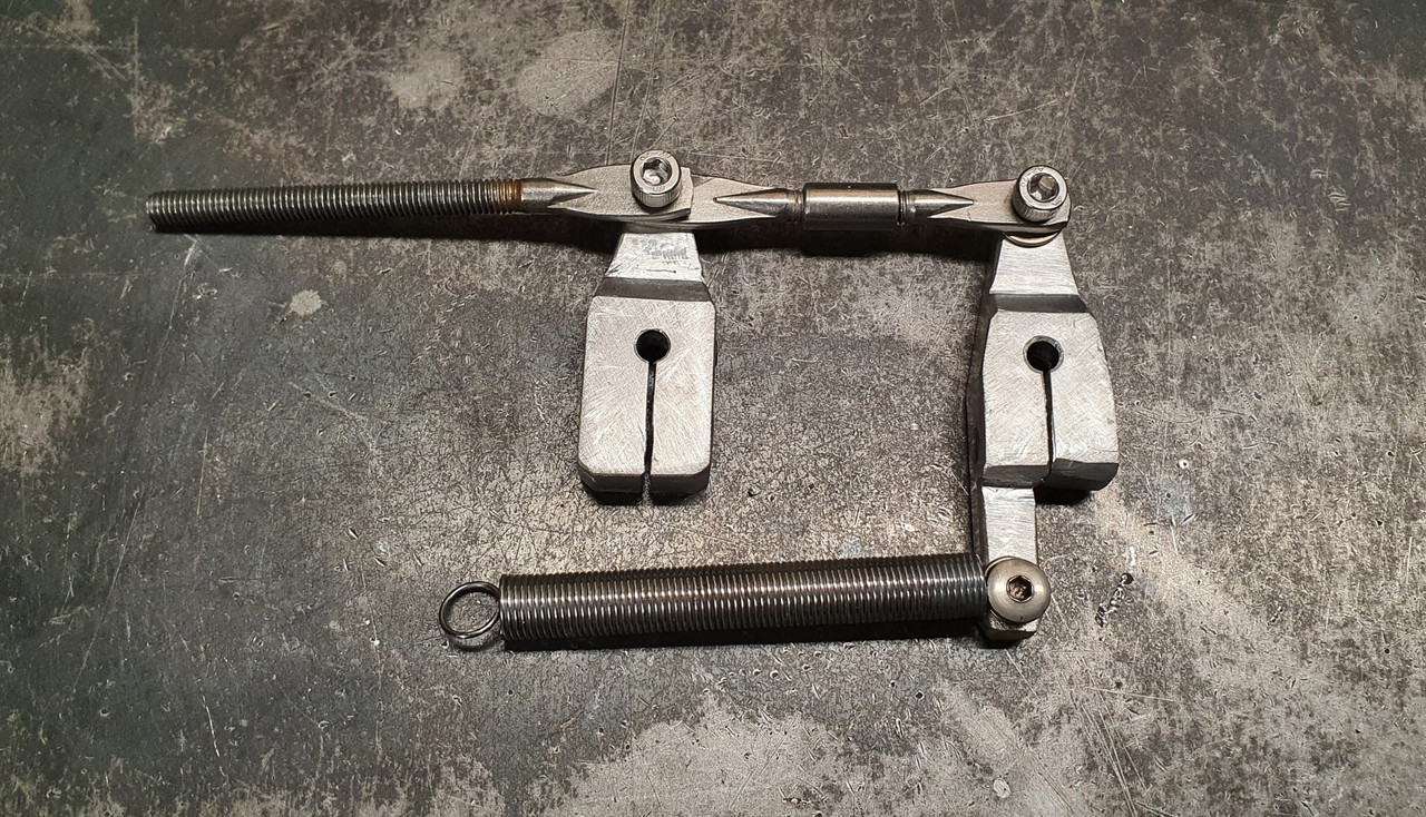
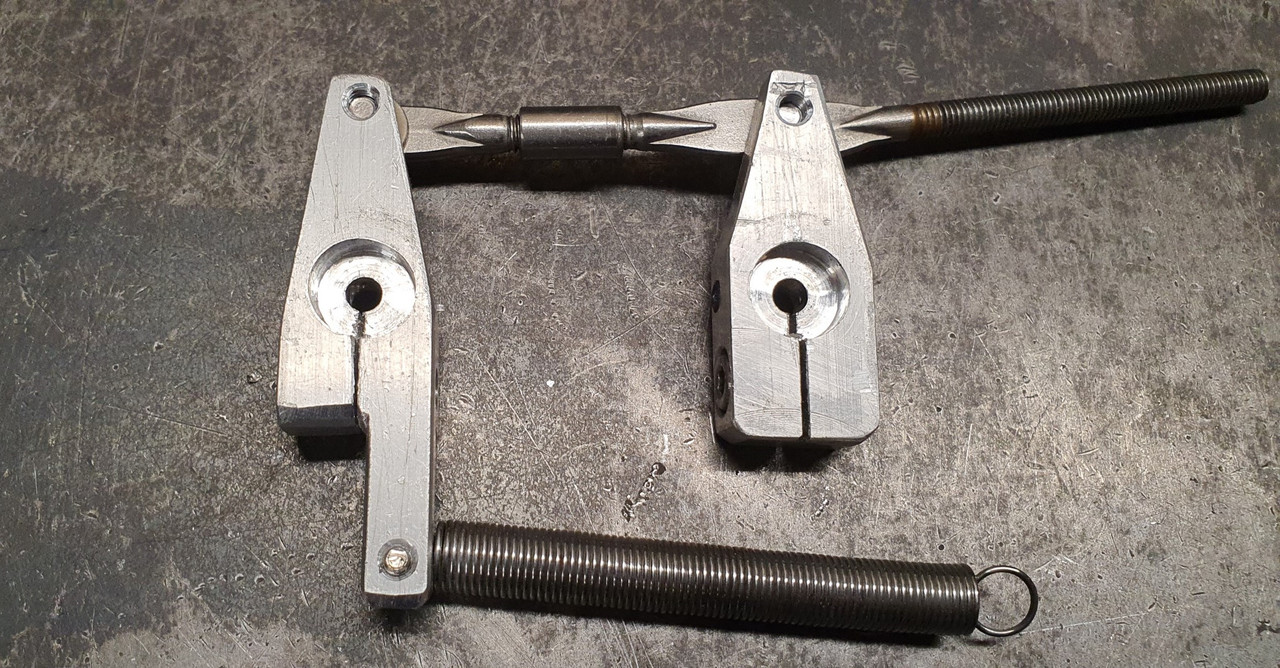
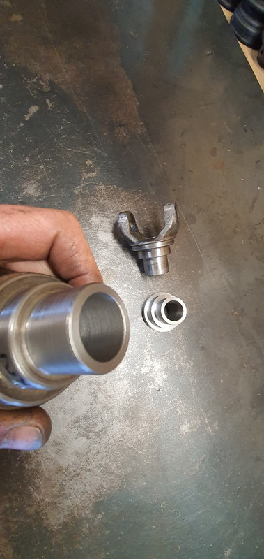
Shrink some bored out yokes cut off from some spare axles. Plenty of meat, will never let go and even if they somehow did loosen and spin they cant come out because there's not enough travel in the CV joint to allow them to. No welding needed. He's run axles done in the same way with some serious big block power and they never let go. Just has to be accurate and luckily its the sort of machining/fitting job I like.

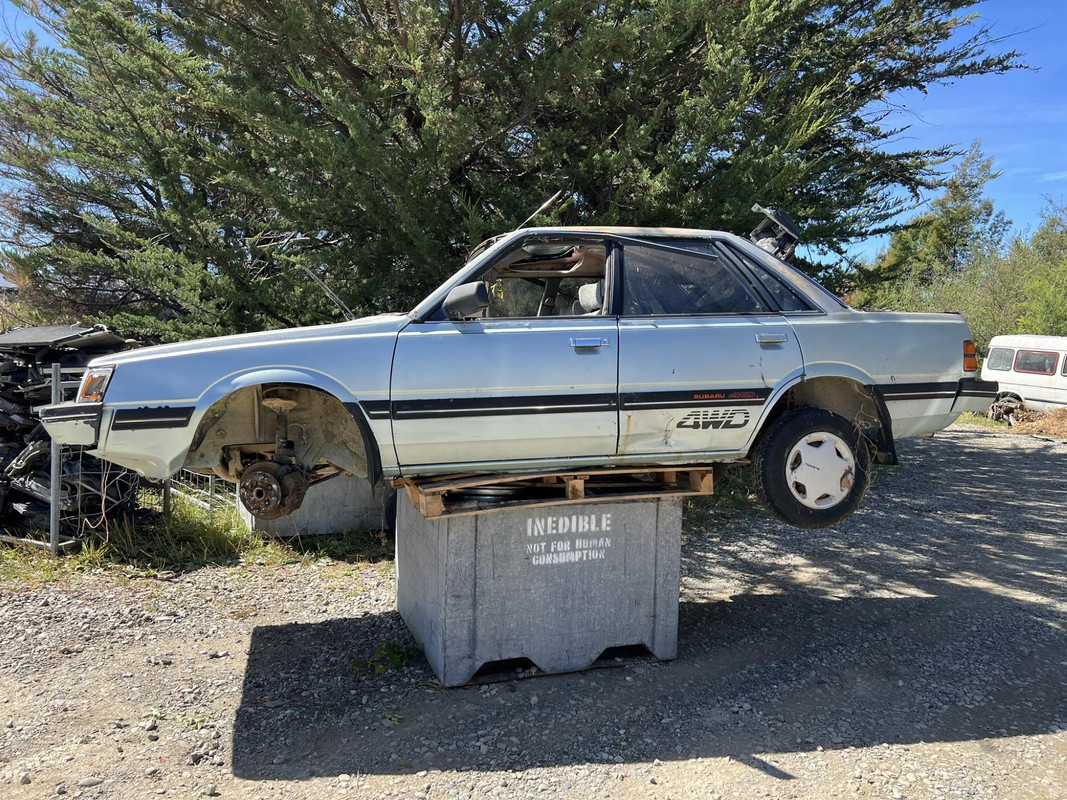
But i needed to start with almost full length scooby shafts to do it, of which I was now down on.. Roll eyes and back to the wreckers to see this beauty get pulled from the hedge...

Image

Image

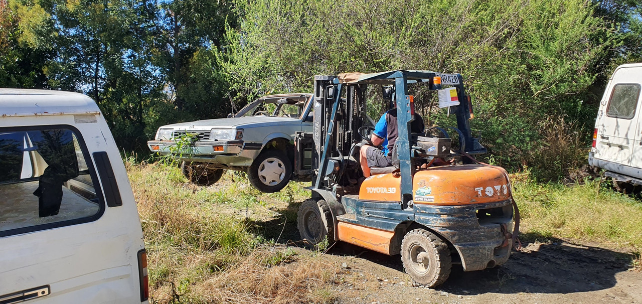
Hannah helped me remove the shafts. It was her birthday too so wow, what a treat. She got visit the wreckers and get oily.

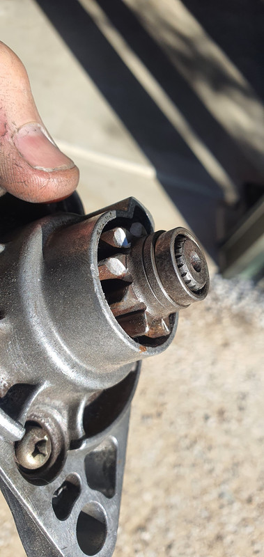
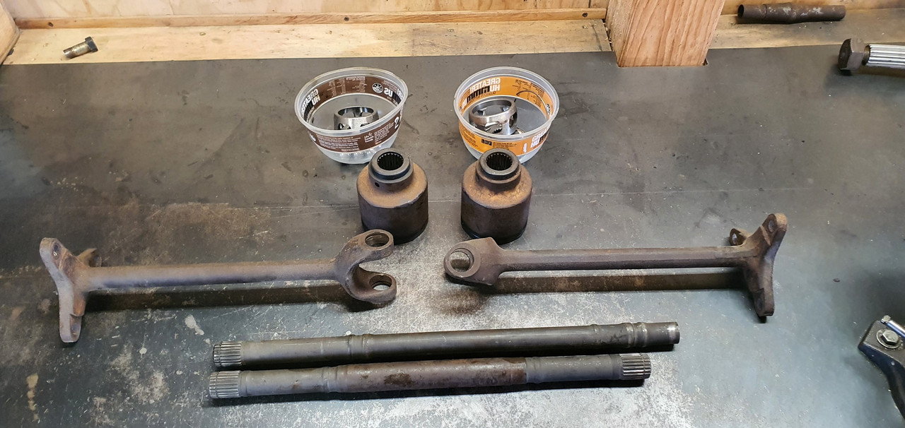
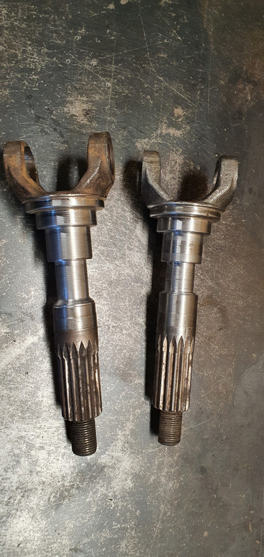
Got home and the shafts didn't fit my CVs. Bigger diameter end. Really weird because I checked online... ha. It lies. Turns out some late 4wd Leones had even bigger axle ends than the Imprezzas. Also odd is that one shaft is 22mm and the other side 24mm, although both the same length.

Back to the wreckers.

Image

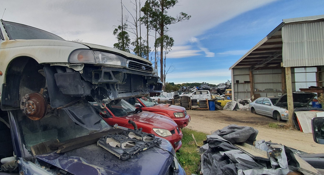
This time I got larger 25mm shafts with the smaller ends from front wheel drive Imprezzas. I grabbed two pairs. Same again, 22mm on one side and 25 on the other. Now I had two of each. Got home and spent some time cleaning them up, outside because petrol fumes.

Image

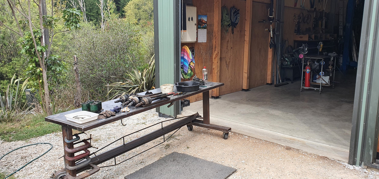
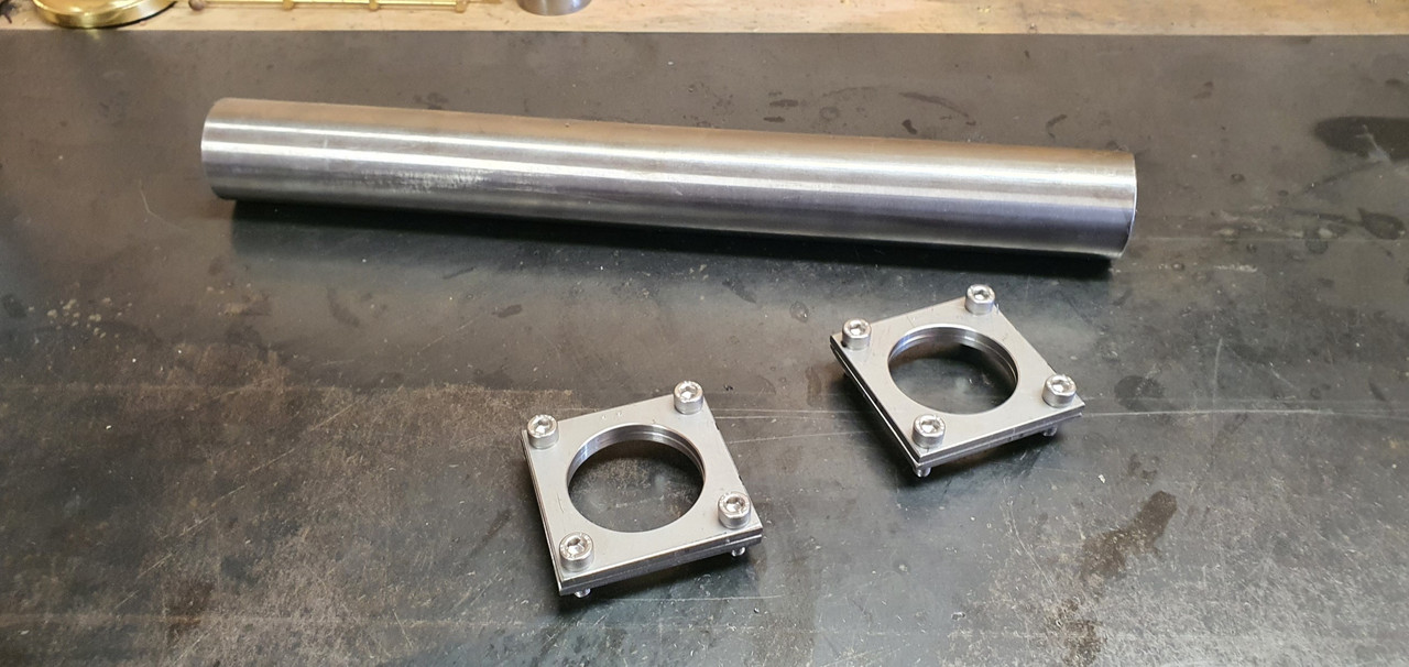
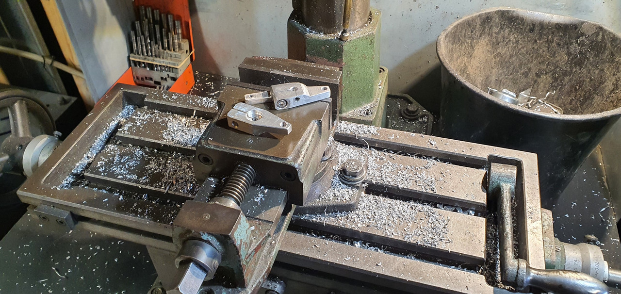
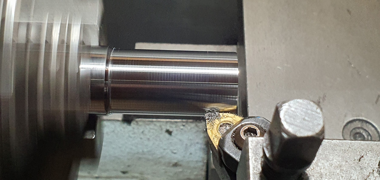
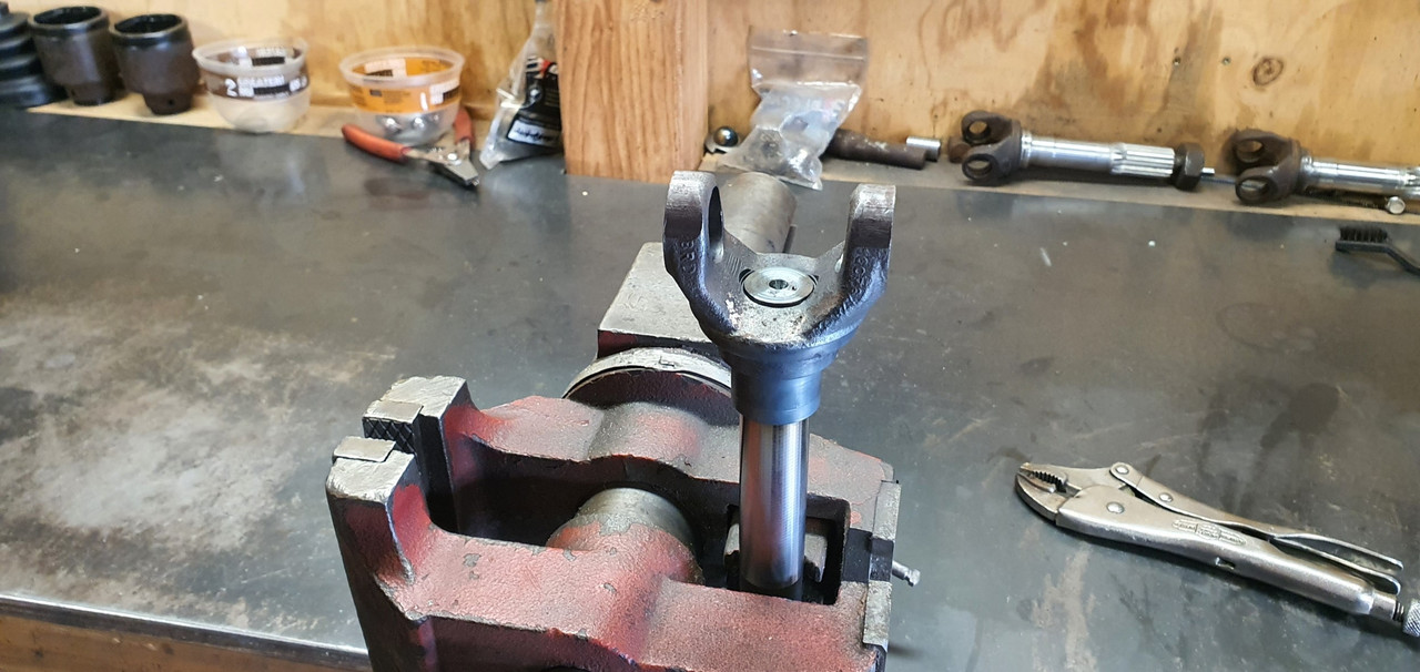
Cleaned up the spare pair of axles in the lathe to make sure I had an accurate clamping spot for the later boring.

Image

Good quality steel! I turned them down to less than the 23mm bore size and chopped the yokes off.
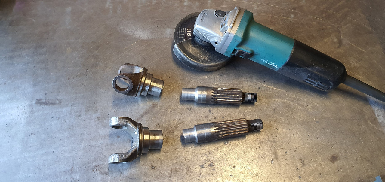
Image

Image

Made lots of swarf

Image

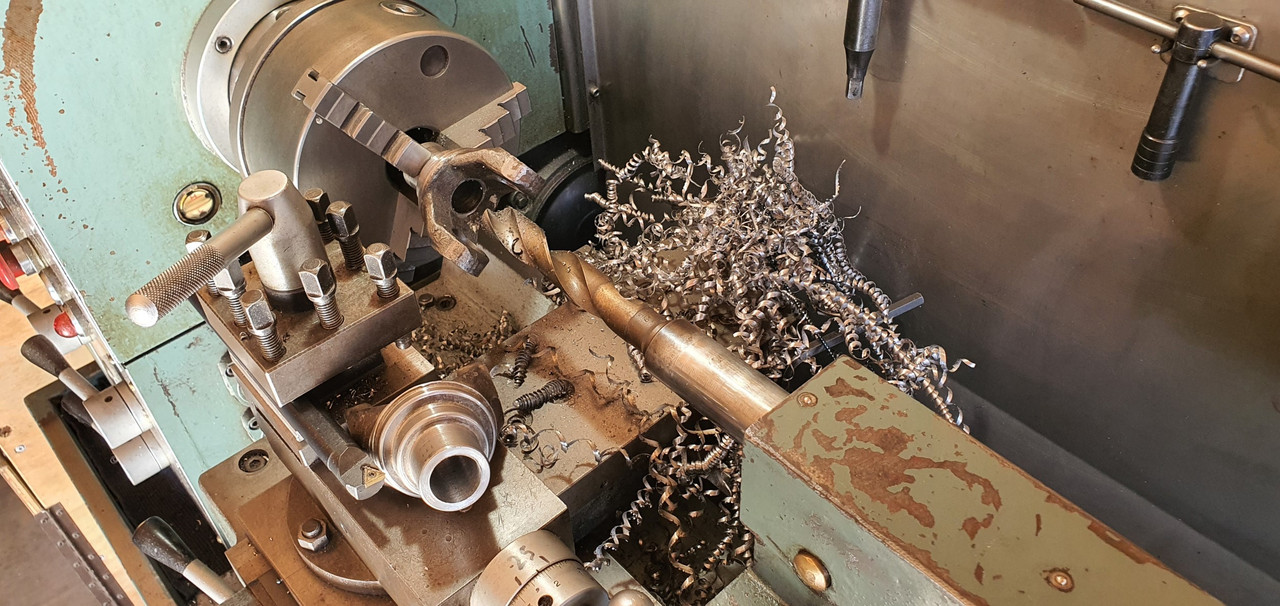
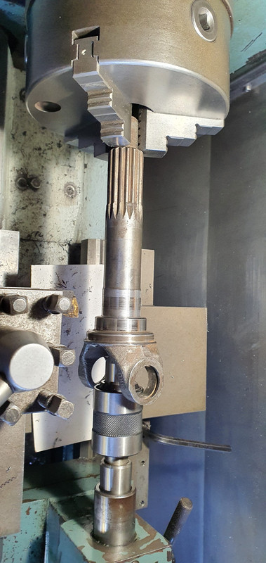
Bored out to bang on 23mm with nice radius.

Image

Image

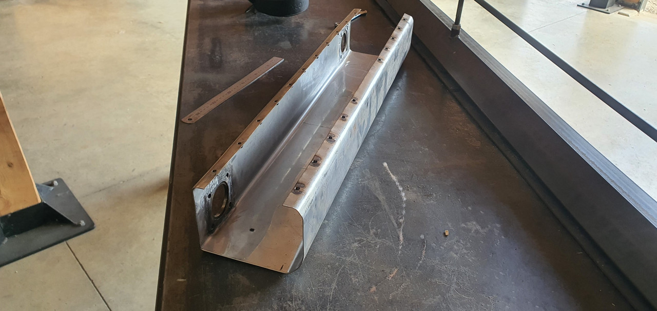
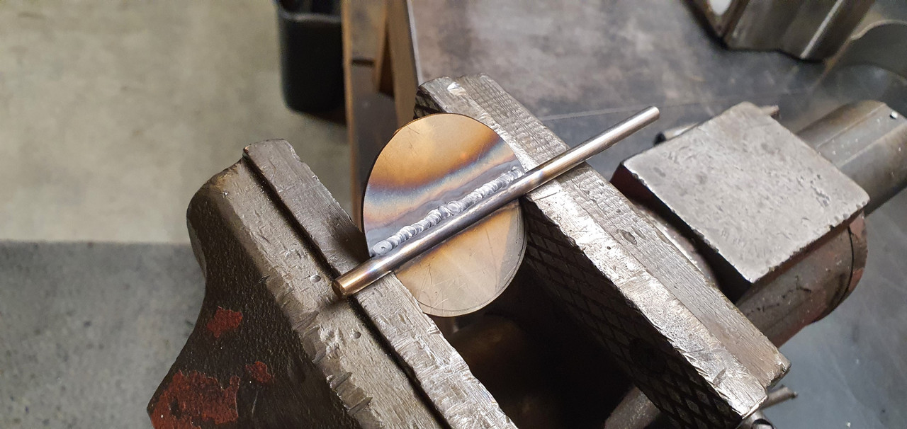
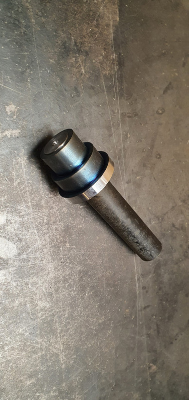
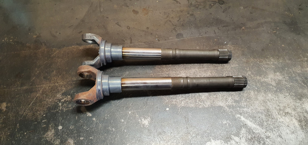
Double checked and triple checked I had my lengths required correct. Chopped the two 25mm scooby shafts down to length and turned a step down on one end of each, a radiused step to stop any stress risers.

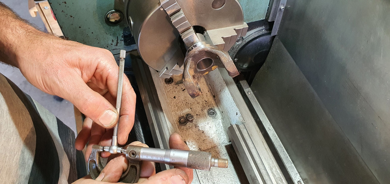
I went for .0015"~.002" interference. Go online and see the debates between all the barries about what a good shrink fit should be :grin: There's many variables as well. I consulted my old faithful machinery's handbook.

Image

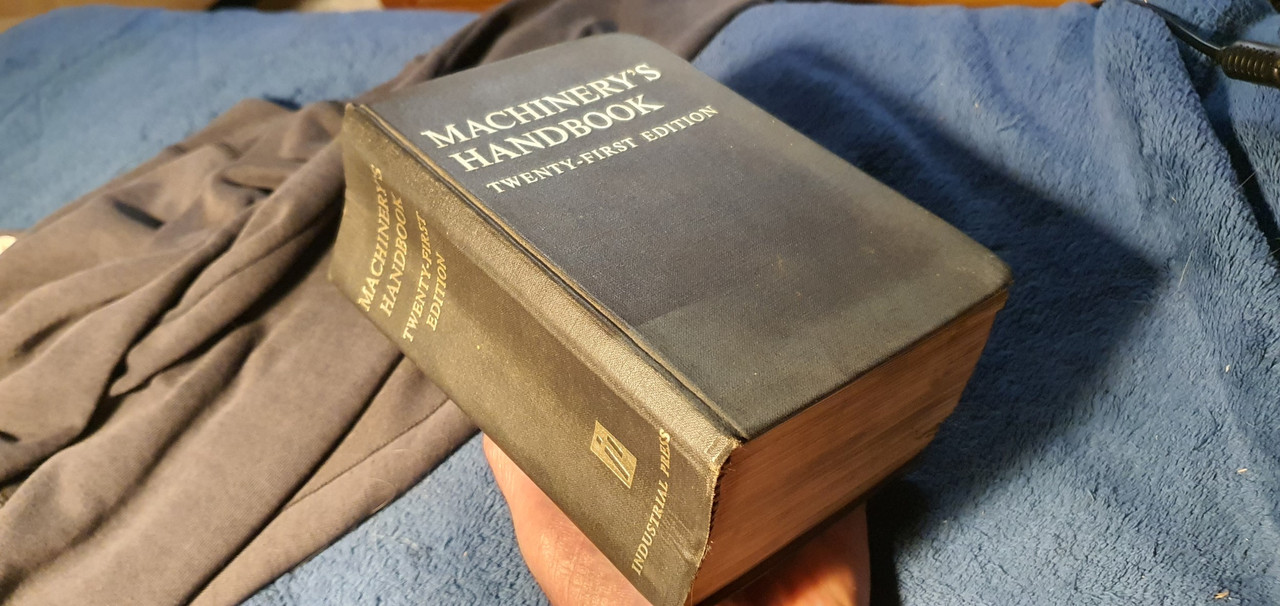
I wanted it tight, but not stressed. Luckily the axle is of good steel.

I also made a sample first, using one of the cut off bits of scooby shaft and some 4340 I machined to the same outer dimensions as the yoke.

Image

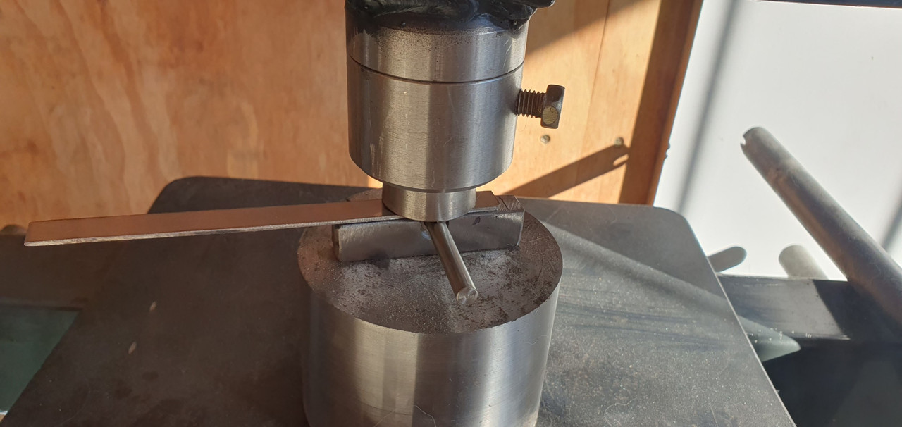
This way I was able to test how hot I needed to get it to expand enough to drop in place. I'll take this to a local engineers who have a press with a pressure gauge and see how much force it takes to wreck this thing :)

Here's about a one hundredth of a millimetre (iirc) getting removed..

Image

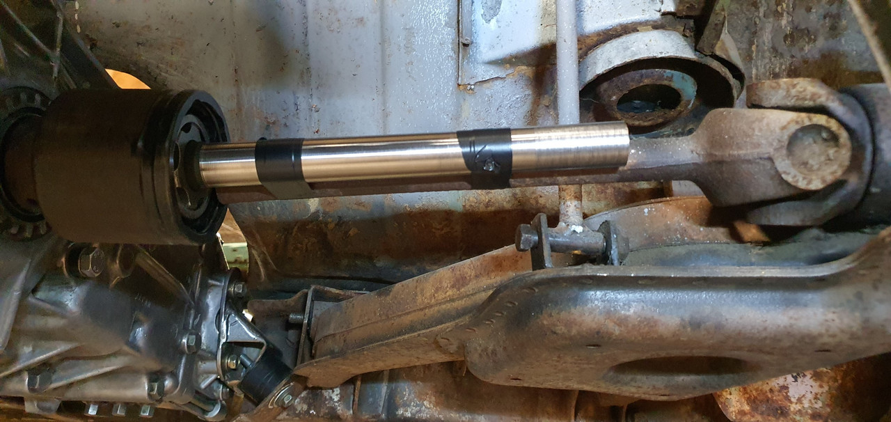
Then things got hot.. photos taken after it was done because I had to move bloody quick! Hannah would grab the torch off me and I would drop the yokes in place. It was a tense bit of time. If the yokes teetered and grab they'd pull the heat so quick and shrink in place before getting to the shoulder. No removing them without damage and I only had the one pair of spare axles.

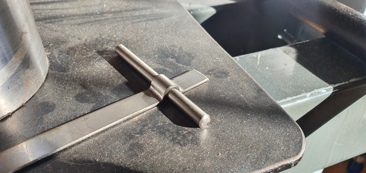
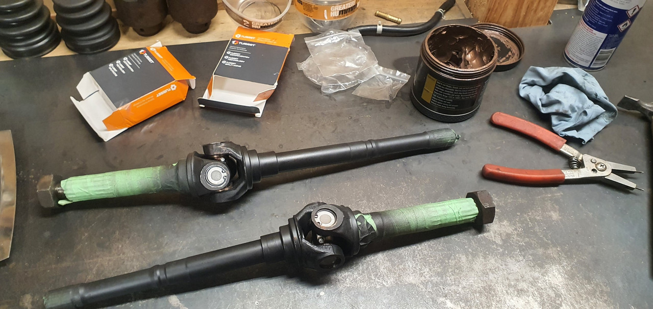
It went well. I was happy and relieved.

Image

Image

Image

The light rust flashing off on one is simply due to that one having been left nearer the front of the workshop to cool down and it was a chilly damp start to the morning. They wired brushed up neat as, got painted with black epoxy and when that was set they had new universal joints fitted. I cant try them on the car until I remove the existing axles from the hubs but it should be fine.

Image

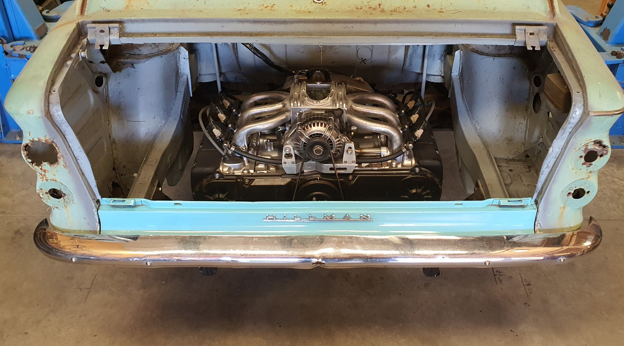
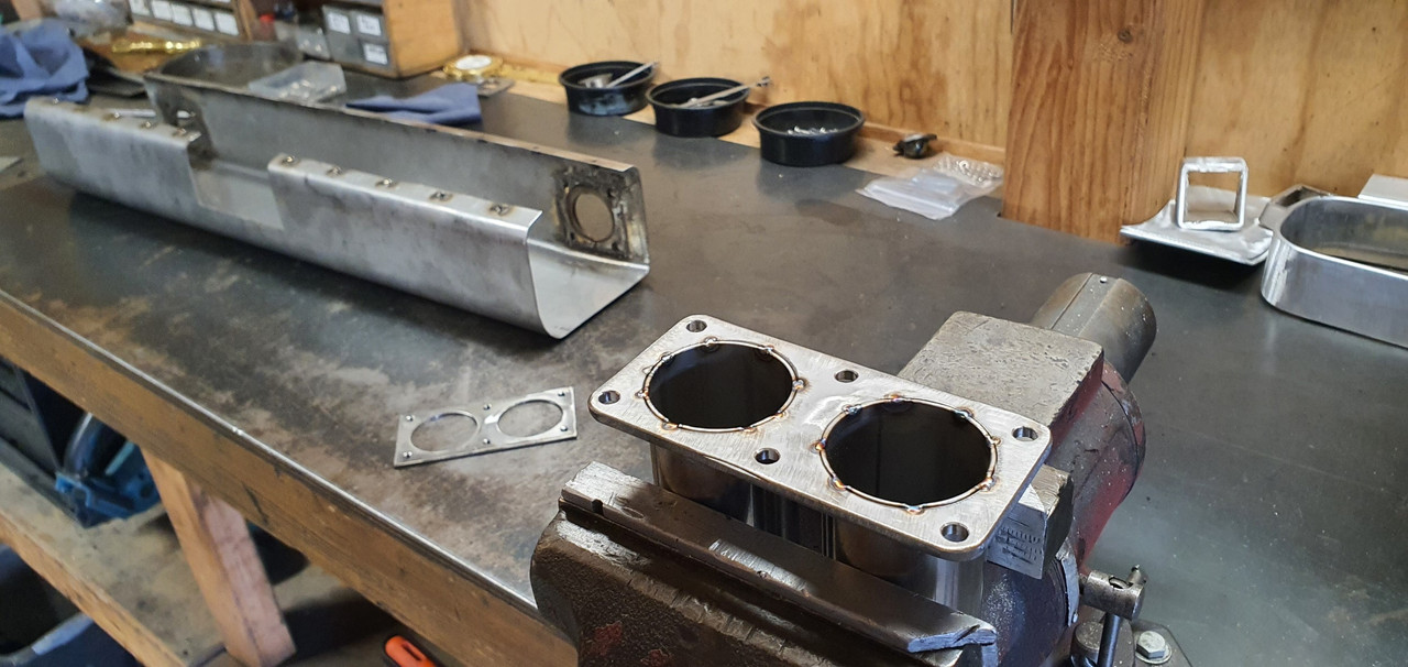
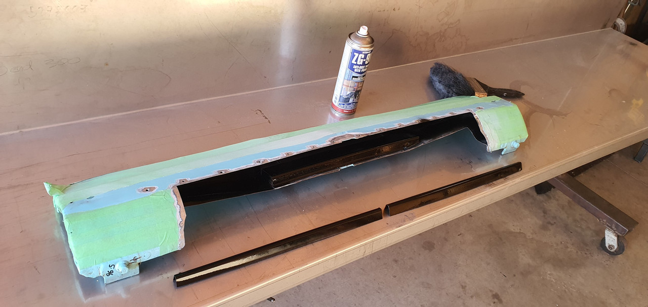
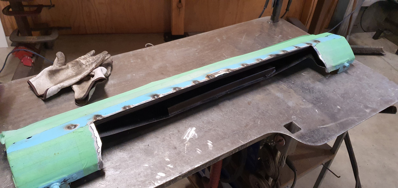
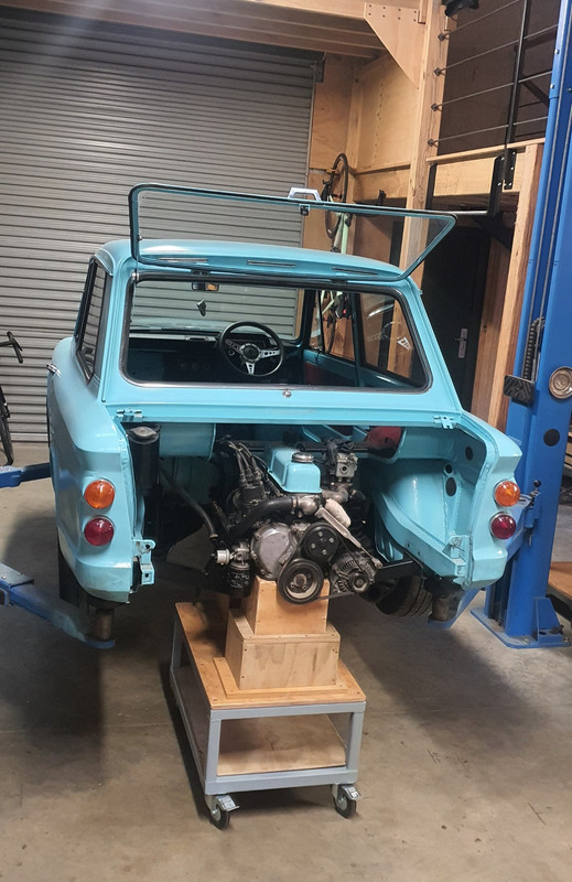
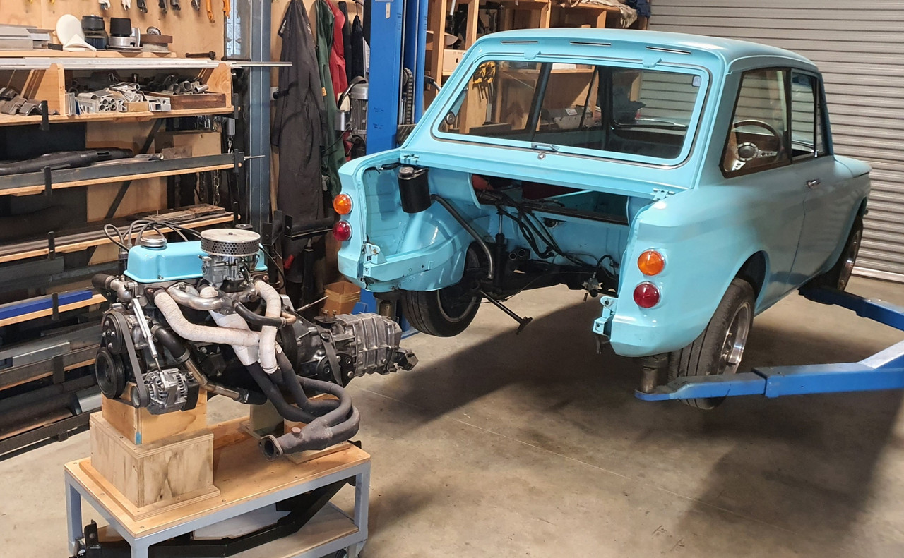
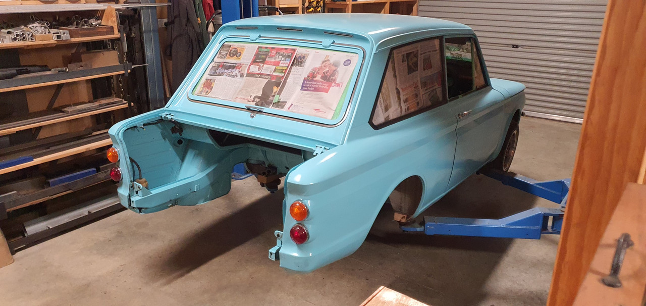
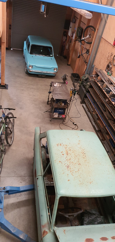
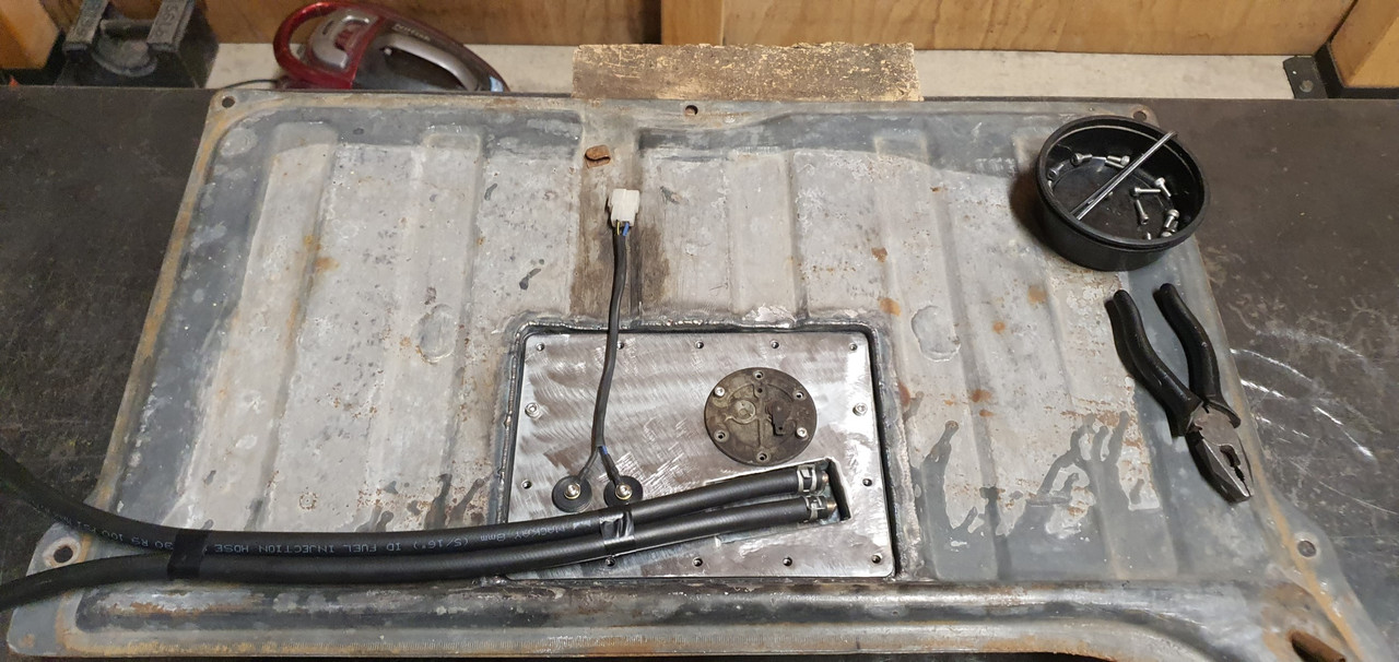
Next up was to sort the fuel tank out to suit fuel injection. I brought the blue imp in and checked a few ideas out on what I could do.

Image

I don't really have room for a surge tank and I never liked the noise on my Viva from the external fuel pump anyway. Nor did I like the way the fuel in the surge tank heats up.

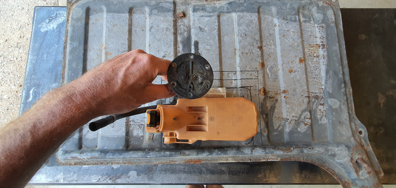
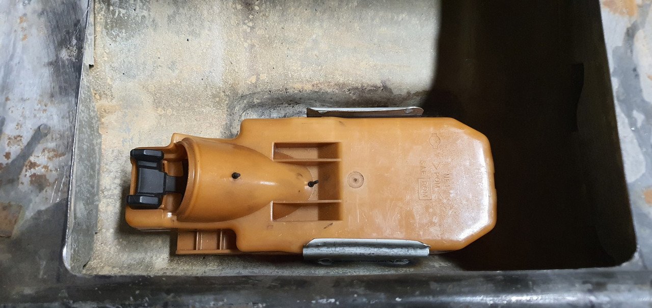
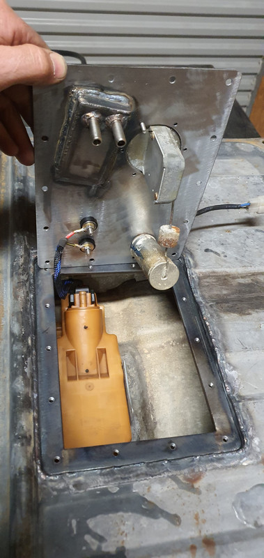
Enter the humble Nissan Micra k11 intank fuel pump and surge container...

Image

Image

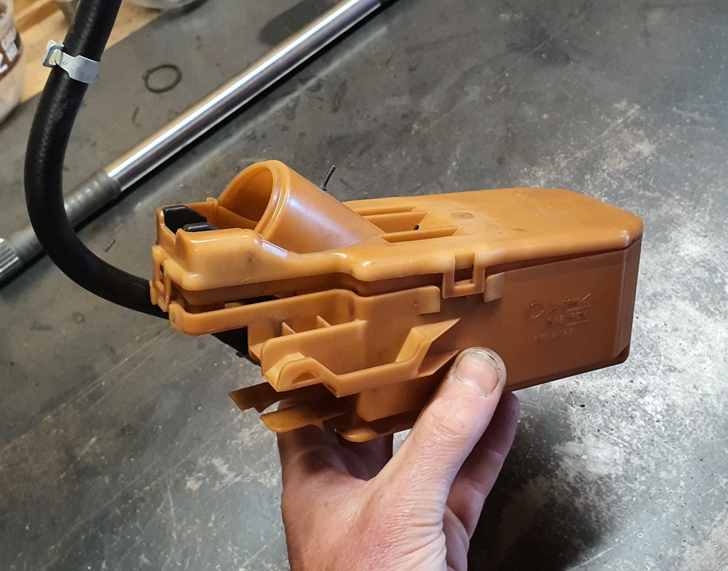
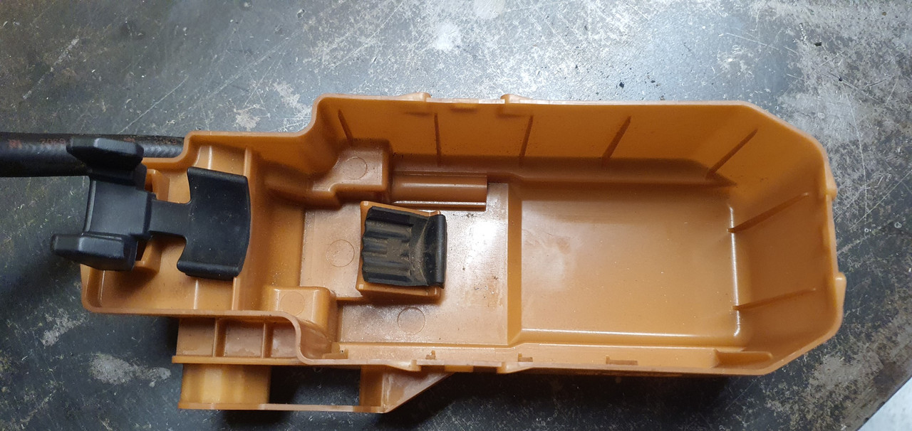
It actually looked like it was just going to fit into the pressed depression at the bottom of the imp fuel tank..

Image

With enough room to run the imp fuel float sender next to it.
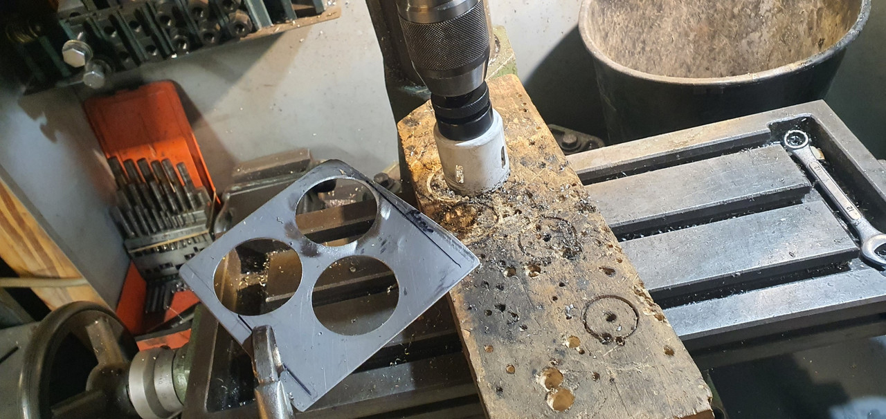
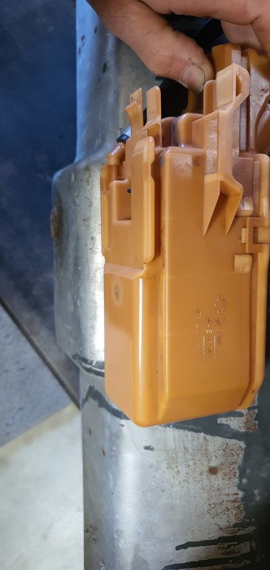
Image

Cut a hole..

Image

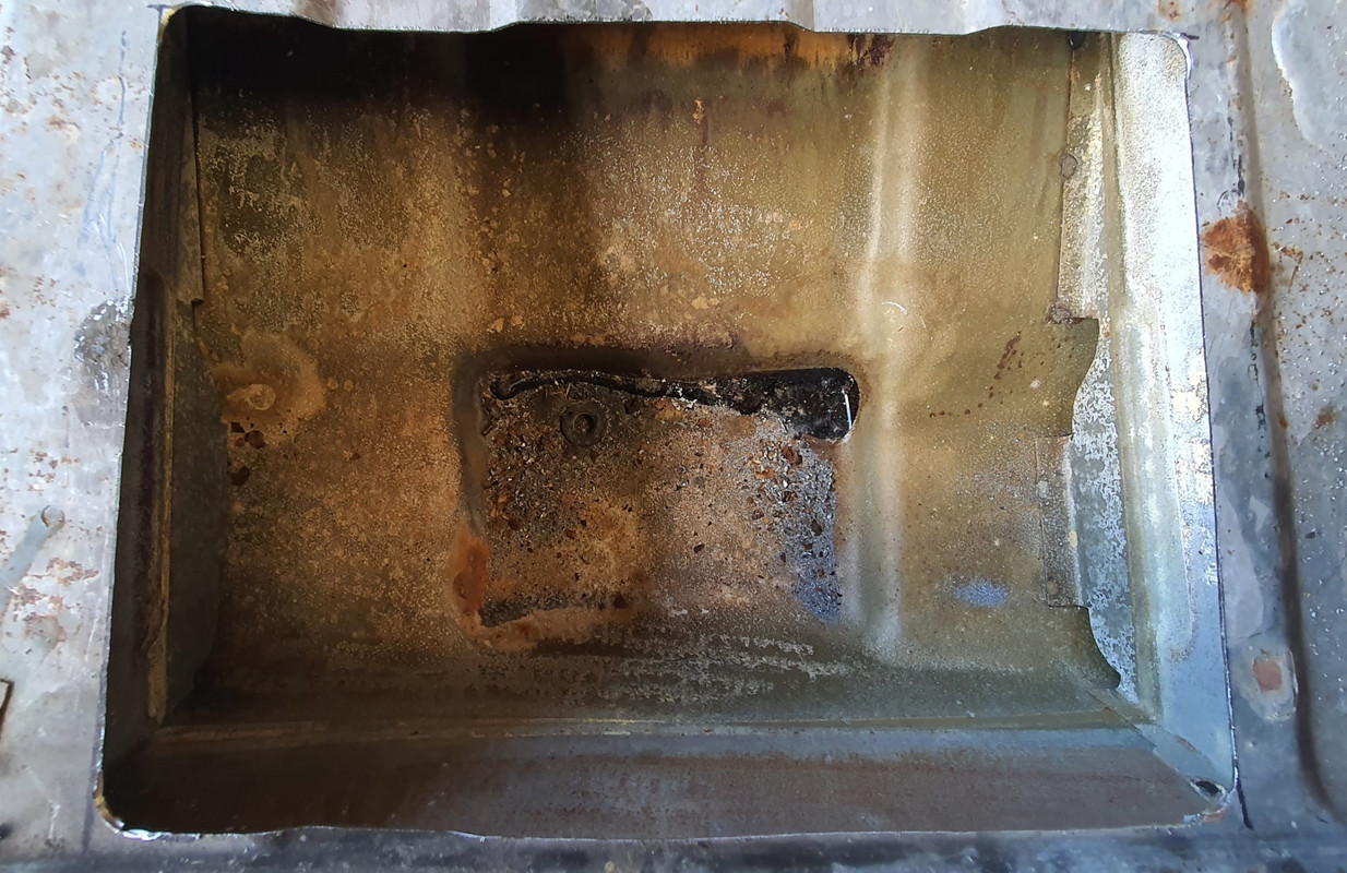
It fits. I'll cut the bracket off the side at bottom of pic and it'll move sideways a bit more..

Image

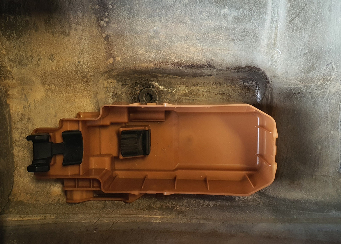
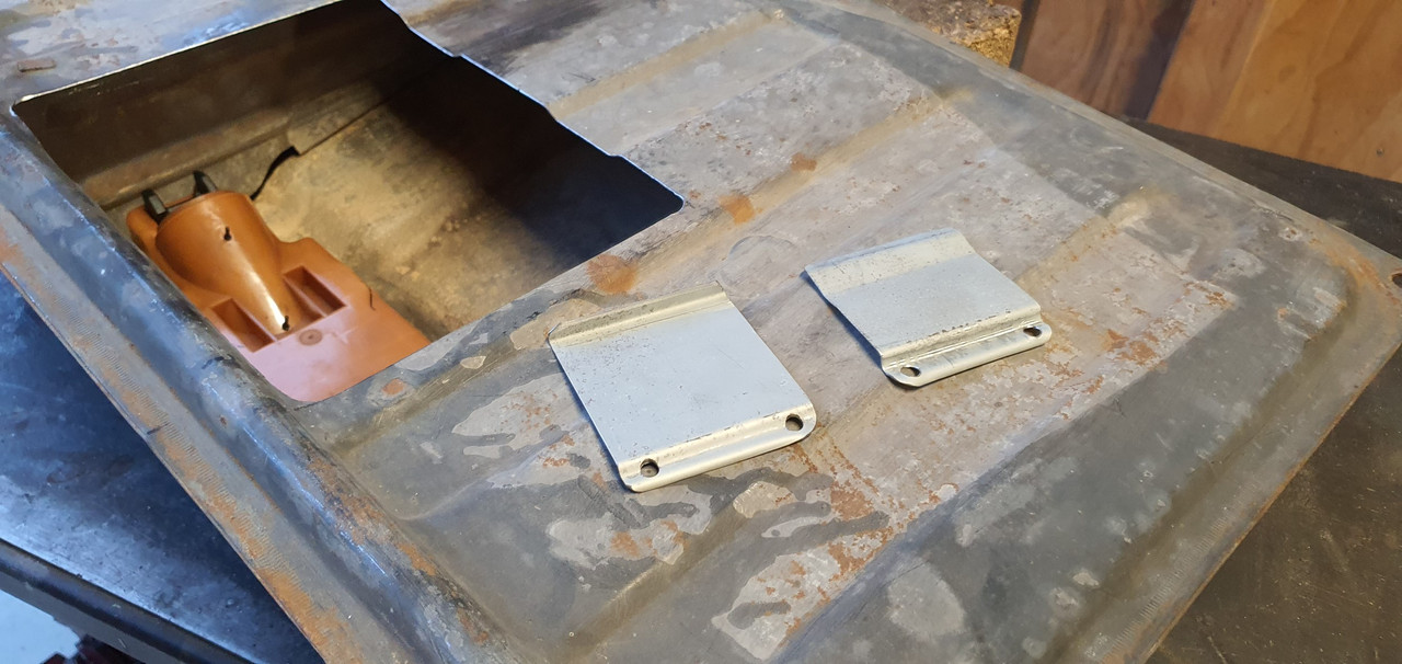
Made some metal brackets

Image

Welded them in and now I have a cradle that takes two cable ties across the top to secure.

Image

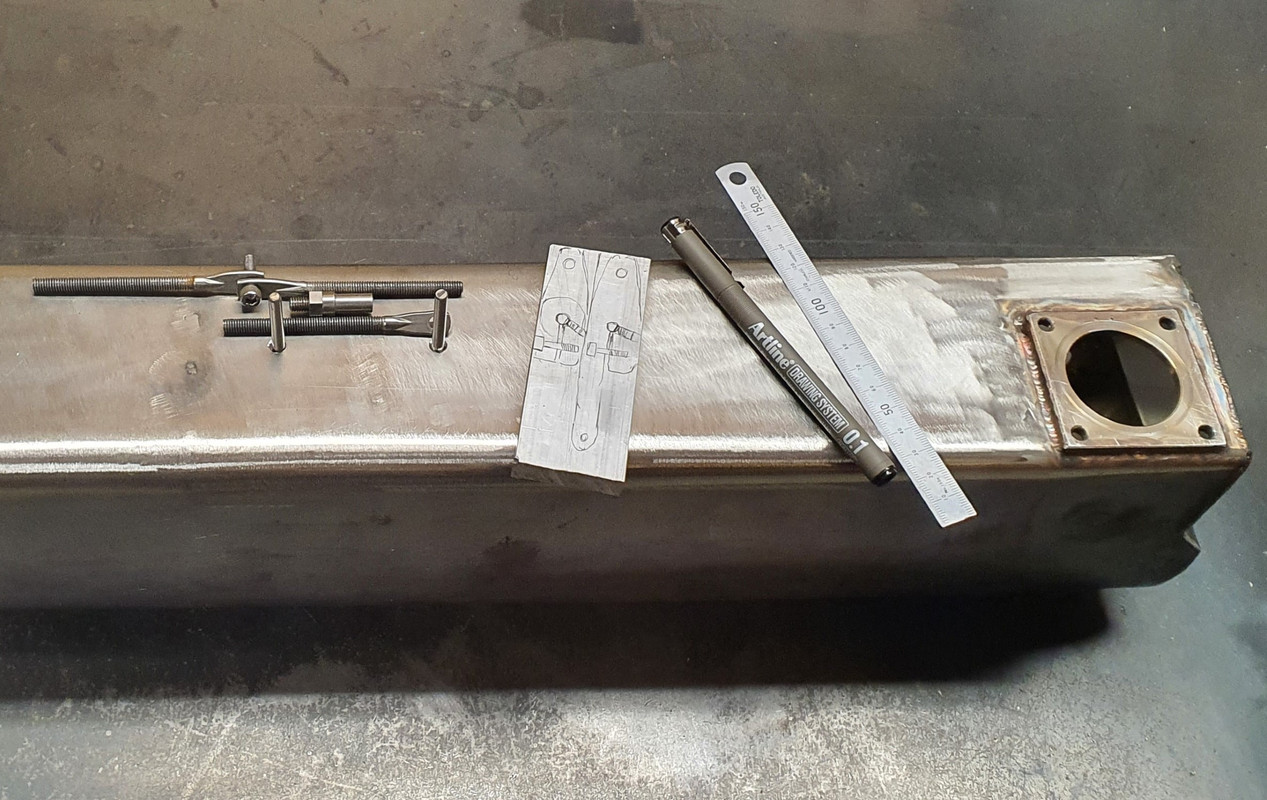
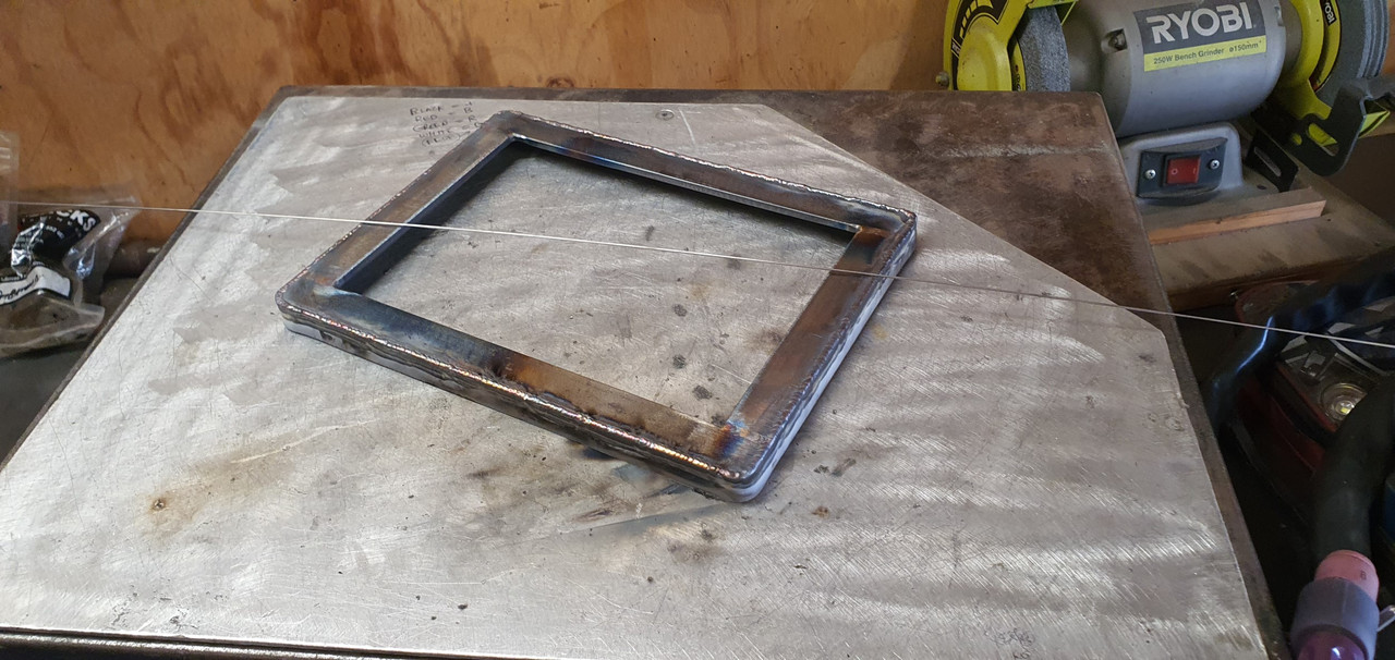
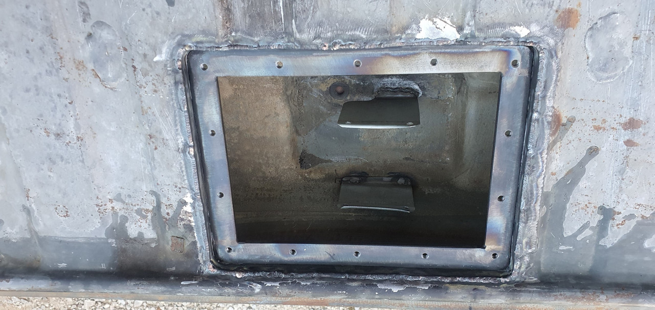
I needed a flange....

Made this. Its designed to recess the lid about 10mm below the tank top. I want to keep the tank top as flat as possible. It'll have the usual layer of foam over top but I don't want things sticking up proud when the 'frunk' is being used (cant be tearing those bags of concrete now eh....)

Image

Many holes drilled and tapped..

Image

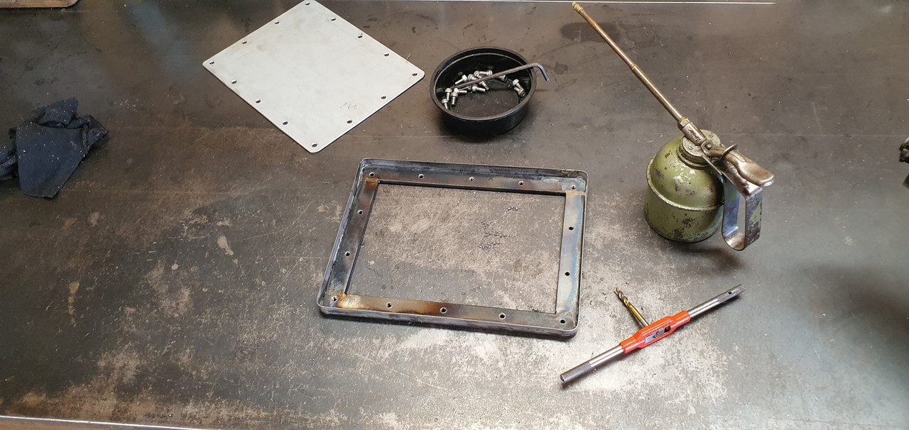
Carefully welded in place. Was a tricky job. Thin steel on the tank that had some sort of (probably poisonous) coating. But happy with result.

Image

Image

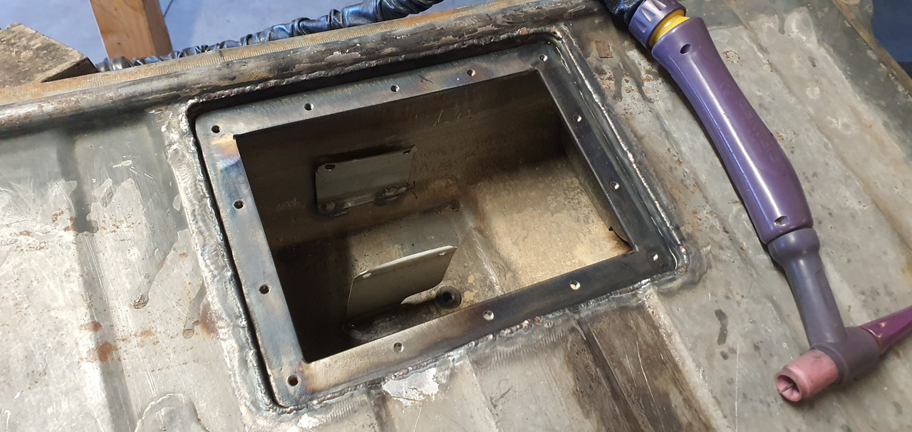
I made another hole...

Image

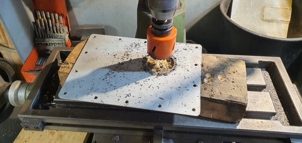
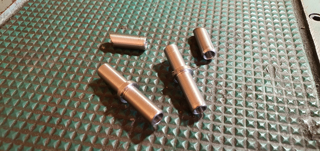
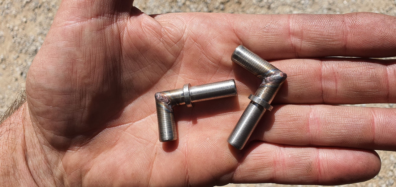
That takes the sender. Drilled and tapped more holes to suit. Now I needed to get fuel from the outside in and from the inside out. I machined up these in stainless..

Image

Thought of a neat way to hold the little bits together for tacking. Blue tack. Or blue tack tack?
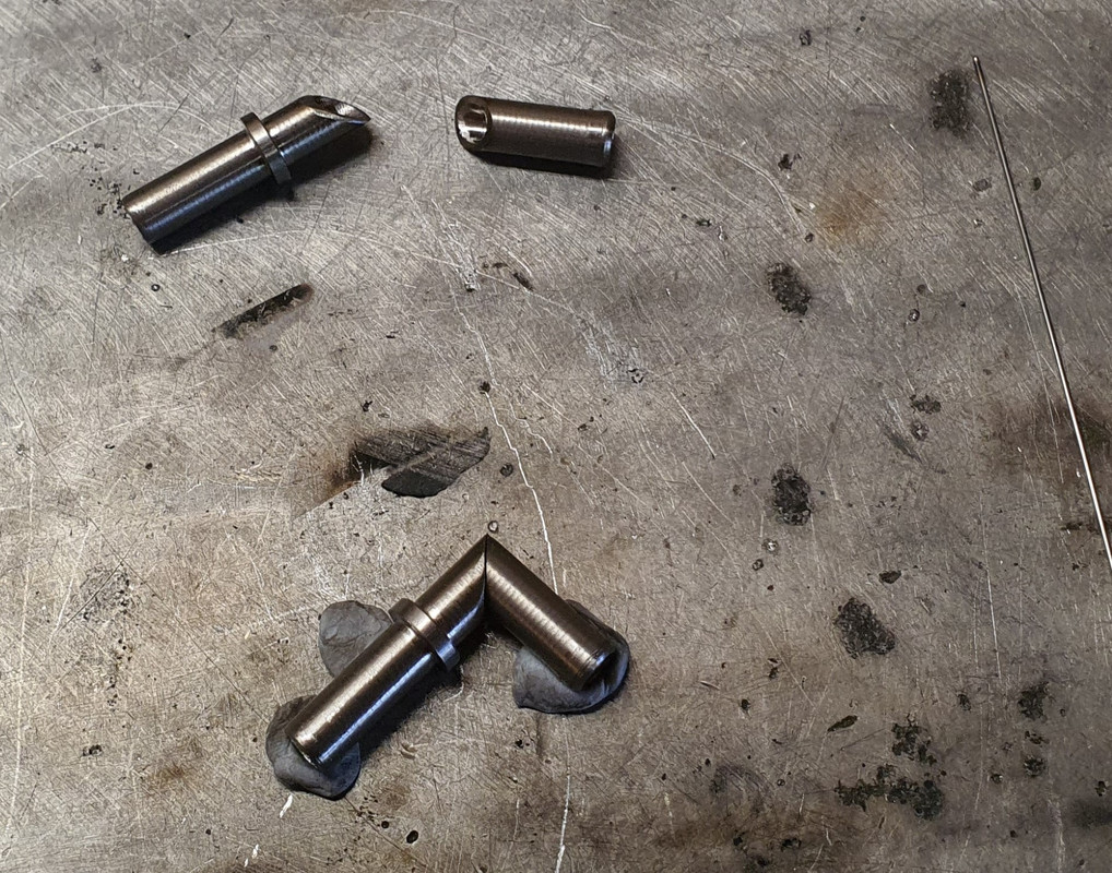
Image

welded up..

Image

I made an angled recess into the hatch cover so the fuel hose goes even further below the tank line.

Image

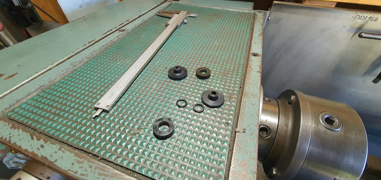
Visible in that photo are the cable connections. Again - I needed to get power in. I machined some shouldered fittings in plastic..

Image

Luckily the micra pump so handily just uses a simple connector with 6.3 spade terminals.

Under the lid...

Image

Tank hard work done. I'll paint bits and cut some gaskets.

Speaking of gaskets. One of mine between my oil filter pedestal and the block is weeping oil. Plus one of the bolt heads weeps. Typical. Put a Japanese engine in a British car and turn your back for a minute...

Image

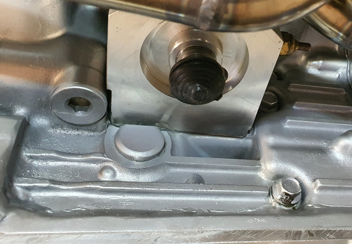
I've already drained the oil cleaned it up and ran a smear of paintable sikaflex along it and around the bolt head. I didn't take photos because not really exciting. I'll paint it silver and no one will know.

Except you the reader.
Last edited by yoeddynz on Sun Mar 17, 2024 7:46 pm, edited 1 time in total.
User avatar
PeterK
DDK rules my life!
Posts: 1069
Joined: Mon Sep 01, 2014 3:04 pm
Location: GU51 - Fleet, Hampshire, UK

Re: 1965 Hillman Imp soon with flat six from a Honda

Post by PeterK »

yoeddynz wrote: Sun Mar 17, 2024 8:11 am I consulted my old faithful machinery's handbook.

Image

Great update.

Clearly, I'm even more old school - my Machinery's Handbook is the Twentieth Edition :lol:
'79 Targa - restoration now mainly complete & being driven
viewtopic.php?f=28&t=59756
yoeddynz
DDK Fanatic
Posts: 55
Joined: Wed Feb 01, 2023 9:02 am

Re: 1965 Hillman Imp soon with flat six from a Honda

Post by yoeddynz »

It's a great book eh. Very handy!!!
yoeddynz
DDK Fanatic
Posts: 55
Joined: Wed Feb 01, 2023 9:02 am

Re: 1965 Hillman Imp soon with flat six from a Honda

Post by yoeddynz »

As per the title this next stage of building the exhaust silencer/muffler/back box/ take your pick has taken much more time and effort than I had always expected.

I started by taking the blue imp apart. To Woolf valley garage I went....

Image

..where I removed (rusty mild steel) exhaust, bumper and rear valance..

Image

Popped it onto rusty imp shell...

Image

Now I knew exactly how much room I have to play with.

Whatever I was going to build had to work with several things.

I wanted the box to be mounted higher than the existing one behind the Datsun engine as I was sick of scraping it on steep driveway exits.

It had to be built completely of stainless steel, no exceptions. No more corrosion.

It had to look tidy and fit within the bumper line, tailpipes excluded.

The tailpipes were to be twin centre exit. I had a very specific look in mind and they have to be just right.

It had to be quiet enough and yet still sound sporty. This last one is tricky and will most likely need modifications to get right hence the last design point...

It has to be modular, easy enough to disassemble and repack with sound deadening (most likely glass fibre)

Now I knew the size I could build it to I started by making some flanges. This so I can unbolt the flexible sections between the V clamps and the box. Made to suit the 44mm tube as per the tube off the V clamps.

Image

Lifted the big folder we'd made onto the bench top and folded up some 1.2mm stainless. Although heftier than I could have used I've gone with this thickness to helped avoid the tinny sound thin stainless boxes can make.

Image

I wanted perforated stainless tube but couldn't find any within NZ. Got some perforated sheet instead - again 1.2...

Image

Which I cut strips from and formed up into tubes as such...

Image

Image

Welded...

Image

Now I had the start of a box and some tube. I could sit down and nut out a design. I have had some basic ideas for ages on how it might look inside but it was really good to sit down and see how it might work. Drew some ideas up..

Image

Nutted out something I think would work well and be easy enough to change if need be. Time to commit. I had to cut some blue steel. First actual act of modification to the imp in my quest to plonk a flat six in it.

Image

Now I could double check box sizing and weld the flanges in place.

Image

Folded up the second box side..

Image

Complete with captive nuts to suit a lid..

Image

Tail pipe time. I almost went with twin 2" exits but they were just a tad too big. Settled on twin 45mm.

Tacked them to yet another stainless pair of flanges to work with the modular design aspect. Happy with the look I then fully welded them on the inside. The flanges will be sealed with a soft copper gasket.

Image

Happy I had the look right I cut the centre top from the box, created a recessed bit and carefully welded in the second threaded flange.

So now I have inlets and outlets where I want them and just have to connect the dots.

Ideally a nice long a route to dampen sound while keeping it as smooth flowing as possible.

Plus, as per original brief, it has to allow for easy disassembly and re-packing.

There was quite a bit of head scratching with this bit of the build but eventually I sorted a design out.

I cut various bit of sheet and put big holes in them with a nice brand new holesaw set.

Image

Made little boxes with more big holes...

Image

Shaped bits like a heart...(#putmyheartandsoulintoit.....)

Image

Welded the ends onto the main box, curved in bit to help with flow and also hide the external bobbin mounts from view a little.

Image

Now I had a collection of parts that would come together and form a london underground of tubeways for the exhaust gases to follow.

Image

I was pretty happy with the layout for its potential silencing effect. However I now wondered if it might just end up being a touch too quiet and restrictive.

Luckily I had come up with an idea early on where I could add some valves. Quite a little bit of extra work involved but the more I'd thought about it the more I was convinced it could work well. With this in mind I had built the middle chamber width to allow for some valves and made sure they could be removed to fit said valves in place.

I cut some 44mm holes in the middle chamber lids and made some to valves to suit...

Image

Whipped up a little press form to create brackets..

Image

Image

Valves mounted.

Image

Underside of lids have the heart halves which help direct flow from one tube back too the next, or up and out through the open valves..

Image

Image

Valve shafts stick out through back of box. Sealing will be by a combination of spring loaded fibre and silicone washers.

Image

Now for an exciting point in life that every shed 'Barry' looks forward to. Emptying out those boxes of little random fittings that have been stashed away 'just in case you might need them'...

Image

Such fun! I selected my (stainless!!!) treats and scribbled on some alloy.

Image

Made lots of alloy swarf..

Image

Ended up with these levers. Pinch bolted to the shafts along with added grub screws. The short length of threaded rod will be changed for a long length of stainless rod, actuation method from within the car yet undecided. Possibly a 12volt door lock motor etc or maybe mechanically with a bicycle cable.

Image

Recessed the backs to allow for seals..

Image

So yeah. Lots of parts! Compulsory photo of thing exploded into many bits...

Image

All together now with some arrows. Remember each side is just a mirror of the other side (there is a small cross over hole in the centre plate that separates the sides)

Valve closed...

Image

Valve open...

Image

I think it'll be quite a difference in sound and look forward to hearing it.

The valves can be seen in action in this very exciting video....

https://www.youtube.com/watch?v=vrc-HKKRgb8

So It's pretty much complete except for the mount points which I'll do once I've got some bobbins from engineering shop along with seals. The lid will be sealed by running a bead of silicone which I'll let set before clamping the lid down.

Oh I weighed it too. I was worried it might end up quite hefty but it will be only about 6.4 kg once all the bolts are in/packed with fibreglass..

Image

The box will be painted satin/matt black leaving the tailpipes shiny. Silencer mounted in place...

Image

Image

Image

View from above showing plenty of room for the valve linkages in place.

Image

I ended up cutting a tiny bit more of the valance away so there's room for a stainless heatshield.

Image

I then covered the valance with some masking tape to help prevent it getting too scratched while I put back in some internal strengthening and capping it all off. I'll also be adding mount areas for the bobbins.

Image

I'll remove the engine next and add in the big multi-pin connector to the engine loom.

Then I'll be seriously very close to removing the Datsun engine and cutting out the under seat area just as I have on this rusty shell. Wow!!
Lightweight_911
Nurse, I think I need some assistance
Posts: 16856
Joined: Wed Nov 12, 2003 10:48 pm
Location: Worcs/W Mids border

Re: 1965 Hillman Imp soon with flat six from a Honda

Post by Lightweight_911 »

.

I don't think I've seen another thread with more impressive fabrication skills - fantastic workmanship !


.
Andy

“Adding power makes you faster on the straights;
- subtracting weight makes you faster everywhere”
911hillclimber
Nurse, I think I need some assistance
Posts: 18932
Joined: Mon Mar 10, 2008 6:26 pm
Location: West Midlands

Re: 1965 Hillman Imp soon with flat six from a Honda

Post by 911hillclimber »

Indeed.
To my view is all the engine mount/silencer a bit low in the shell? That is too close to the road?
73T 911 Coupe, road/hillclimber 3.2L
Lola t 492 / 3.2 hillclimb racer
Boxster 987 Gen II 2.9
yoeddynz
DDK Fanatic
Posts: 55
Joined: Wed Feb 01, 2023 9:02 am

Re: 1965 Hillman Imp soon with flat six from a Honda

Post by yoeddynz »

I've actually got about 60mm more clearance now compared to the existing setup that's behind the datsun engine (which has really only been an issue on steep drive exits with deep gutters.

Pics showing current setup for reference...
IMG_20221003_111122_643.jpg
sladey
Nurse, I think I need some assistance
Posts: 8753
Joined: Sat Apr 23, 2005 9:08 pm
Location: Nottingham, UK

Re: 1965 Hillman Imp soon with flat six from a Honda

Post by sladey »

Brilliant work again - thanks for sharing


Sent from my iPad using Tapatalk Pro
The simple things you see are all complicated
I look pretty young but I'm just backdated yeah
yoeddynz
DDK Fanatic
Posts: 55
Joined: Wed Feb 01, 2023 9:02 am

Re: 1965 Hillman Imp soon with flat six from a Honda

Post by yoeddynz »

No probs :)
yoeddynz
DDK Fanatic
Posts: 55
Joined: Wed Feb 01, 2023 9:02 am

Re: 1965 Hillman Imp soon with flat six from a Honda

Post by yoeddynz »

Getting closer!!!

Next job was to strengthen and close up the rear valance.

Pics..

Added internal bracing. I probably didn't need to. Its not really under much stress now without an engine hanging on it as per on an original imp setup. Just closes off the back end, gives something to hang an exhaust on and something for the fiberglass engine cover to latch onto. But hey, I'm only adding a little bit of extra weight...

Image

Image

Gave the inside an extra layer of zinc rich paint ..Image

Closed it up..

Image

Flap disc on the welds and trial fitted it. I won't yet fit any exhaust mounts. i want to weld those on when the engine is sat in the blue Imp so its all done to suit its home as no two imps are exactly the same. It looks neat in place though.

Image

Speaking of exhausts. I needed a bit of rod for a customers job and went searching through the steel rack...

Image

..and I found this bit of stainless rod with an eye pressed in at one end. Its perfect for the valve actuation rod that'll run along the exhaust box..

Image

I've been having a little browse at various actuators on Ali express and I think one of these could do the job well...

https://vi.aliexpress.com/item/10050037 ... pt=glo2vnm

With the valance sorted and covered in some epoxy paint ready for a skim of filler I could now remove the engine from rusty green imp. That's the last time it'll be sat in there.

Not sure what will become of that shell. Maybe garden art? Maybe just chop it up and keep any useful repair panels in case I have a whoopsie with Blue imp? Its not too rusty and could be saved but it would take another fella like me to do such a silly thing to a car where you can buy better shells, rego on hold, for not much money. British imp fans would probably save it though as its a good solid base compared to what I have seen on offer in the UK.

Green imp was then pushed outside into the cold and I sat in front of the wood burner, warm and cosy. I cut the main engine loom in half and let in a big multi plug. I'd been contemplating whether I'd be bothered to do this for some time now and I'm really glad I did for it didn't actually take very long to do. It'll make removing the engine even easier with no need to disturb the ecu wiring under the rear seat.

Image

I then removed the gearbox and made a cover plate for the gap located below the flywheel. The bellhousing opening it covers faces forwards and I don't want to fill it with stones, dirt, dead possums etc.

Image

Removed the flywheel and carefully ground a lead onto each tooth on the Subaru ring gear. Its designed for a different rotation on the starter and in use the starter would sometimes not mesh properly and make a horrible loud 'gnashing of metallic teeth' sound. Not keen on that. I'd also given the pinion a similar grind so hopefully they'll slide in nicer. Time will tell.

Image

Image

I then machined up a basic clutch disc alignment tool..

Image

I refitted the valance and exhaust to the blue imp, drove it into the workshop and then removed the lovely comfy, but not exactly period correct (like as if that's an issue with me....) Tomei steering wheel which will now be fitted into our Nissan Micra.

I then cleaned up the lovely Moto-lita steering wheel that has been hanging on the wall for years since I sold my Viva HB. My Uncle in the UK worked for a short time at Moto-lita many moons ago and got this wheel then. He'd fitted it in several cars including a few Morris Minors. When he died my cousins gave it to me after his funeral.

I'm very happy to be fitting it in the Imp. It's more in keeping and looks great. I was also happy to discover that Imps and Vivas share the same spline pattern so I was able to use the original nicely made boss.

Image

I also removed the stereo, speakers and parcel shelves. The speakers were always in the way and getting knocked by my feet when I entered the car so they won't be going back.

Then all the blankets and other stuff that's accumulated in the imp. Lol at the several British airways blankets that had found their way into the imp...

Image

Next up were the Recaro seats. Out they came. Definitely going back in though. Might not be period correct but they are lovely. In the future, once I've won lotto I'll get them recovered in a more suitable style. Looking quite bare inside now..

Image

I do love the two tone red/black colour scheme on the door cards and the red rear seat.

Image

But I don't love the super sticky flashing tape I'd used to hold down the loom under the rear seat. This stuff is great if you don't want things to move or you desire tired hands trying to remove it.

Image

Now it was finally time to remove the Datsun engine.

Actually now it was time to make a 'Datsun 1200 wheely stand 2000'. I want to have an easier system to remove/refit the Datsun lump without having to use a top mounted engine cradle and sling - a setup that was due to the centre mounted engine cross member. So I made this..

Image

Yes, a bit over built, but it'll find other handy workshop carting uses in the future if the flat six proves itself and the Datsun setup gets sold on.

Fitted sturdy wheels, painted it workshop grey and whipped up a plywood engine cradle with room in the centre to drop the cross member down into.

Image

Now in action. Much easier and way faster!!!

Image

Engine out...

Image

Still a neat little engine. If I was to keep it in the Imp (like said above, the flat six has to prove itself) I'd rebuild it, balanced properly, fit my oval port head, sporty cam, itbs and full engine management. Then promptly destroy the Imp transmission...

Image

Arty shot...

Image

I stripped out the remaining bits from the engine bay, the rear suspension and cross member. Drained the fuel tank, luckily only 5 litres to bother with, removed it and stashed it away in the garage which is now filling up with imp parts.

Image

Brought the green imp back in from the chill so I use it to take measurements from.

Image

Measured and marked out the cut lines where I need to chop out under the rear seat base for the taller Subaru transmission.

Image

Covered the inside glass surfaces with paper. I'll get Hannah to block grinding sparks when I'm doing any cutting from under the car.

Image

So that's where I'm at now. Next job is cutty cutty time.
Post Reply