

Great work and enjoying the unusual route of race car to street car. With the door panels, did you use a 'power stapler' to fix the vinyl to the mdf ? I assume there is foam between the mdf and the vinyl - does this go snug to the edge, or is it trimmed just short to allow the vinyl to wrap round against the mdf rather than the foam ?
Thanks
Ian
2.4E From IKEA to Blut Orange
Moderator: Bootsy
-
Highfield
- Put a fork in me, I'm done!
- Posts: 1519
- Joined: Thu Oct 06, 2005 8:34 pm
- Location: Warwickshire
Re: 2.4E From IKEA to Blut Orange
Ian Highfield
Pre 73 1964 Alfa Giulia Sprint GT MSA Category 1 Rally Car
1992 964 C2 with RS Suspension setup and Sport Interior - SOLD
1973 911T (2.7 Carrera engine and loads of period mods - all steel) - SOLD
1986 Carrera Coupe (256bhp) - SOLD
Pre 73 1964 Alfa Giulia Sprint GT MSA Category 1 Rally Car
1992 964 C2 with RS Suspension setup and Sport Interior - SOLD
1973 911T (2.7 Carrera engine and loads of period mods - all steel) - SOLD
1986 Carrera Coupe (256bhp) - SOLD
Re: 2.4E From IKEA to Blut Orange
Looks great, glad you manger to get the luggage compartment lid to fit. Gaps look great.
Nice to see you last month, sorry we couldn't stay any longer.
Kind regards.
Nice to see you last month, sorry we couldn't stay any longer.
Kind regards.
John
1970 2.2E Coupe.
2004 996 GT3 mkII
2015 Skoda Octavia VRS TSI DSG.
2021 Toyota GR Yaris Circuit Pack
1970 2.2E Coupe.
2004 996 GT3 mkII
2015 Skoda Octavia VRS TSI DSG.
2021 Toyota GR Yaris Circuit Pack
Re: 2.4E From IKEA to Blut Orange
No, you have to get a dial gauge separately. Plenty on ebay.jb wrote:Is the gauge part of the tool or do you have to buy that separately?
It is not obvious in the picture on their site
'Creativity is the product of time wasted' Albert Einstein
1972 RHD 2.4E (ex Bob Watson racer - now in original Tangerine)
1966 LHD swb (Doctors car - now with Mrs. Ferrari in Madrid)
1966 TR4A (now sold and replaced by 1990 944 turbo)
1966 S2a Landrover
1972 RHD 2.4E (ex Bob Watson racer - now in original Tangerine)
1966 LHD swb (Doctors car - now with Mrs. Ferrari in Madrid)
1966 TR4A (now sold and replaced by 1990 944 turbo)
1966 S2a Landrover
Re: 2.4E From IKEA to Blut Orange
210bhp wrote:You can do the clearances with just the lower covers off.
Regards
Mike
You'll have to explain that one Mike. How do you do the upper valve clearance then?
'Creativity is the product of time wasted' Albert Einstein
1972 RHD 2.4E (ex Bob Watson racer - now in original Tangerine)
1966 LHD swb (Doctors car - now with Mrs. Ferrari in Madrid)
1966 TR4A (now sold and replaced by 1990 944 turbo)
1966 S2a Landrover
1972 RHD 2.4E (ex Bob Watson racer - now in original Tangerine)
1966 LHD swb (Doctors car - now with Mrs. Ferrari in Madrid)
1966 TR4A (now sold and replaced by 1990 944 turbo)
1966 S2a Landrover
Re: 2.4E From IKEA to Blut Orange
Hello Ian,Highfield wrote:Great work and enjoying the unusual route of race car to street car. With the door panels, did you use a 'power stapler' to fix the vinyl to the mdf ? I assume there is foam between the mdf and the vinyl - does this go snug to the edge, or is it trimmed just short to allow the vinyl to wrap round against the mdf rather than the foam ?
Thanks
Ian
I used a hand stapler like the one below with 6mm staples, and Garry uses a power stapler. I sometimes have to tap them home with my 'toffee hammer'. There is 3mm scrim foam between the vinyl and the mdf and yes it goes just short of the edge so the vinyl is all that's wrapped around the edge.
Mick

'Creativity is the product of time wasted' Albert Einstein
1972 RHD 2.4E (ex Bob Watson racer - now in original Tangerine)
1966 LHD swb (Doctors car - now with Mrs. Ferrari in Madrid)
1966 TR4A (now sold and replaced by 1990 944 turbo)
1966 S2a Landrover
1972 RHD 2.4E (ex Bob Watson racer - now in original Tangerine)
1966 LHD swb (Doctors car - now with Mrs. Ferrari in Madrid)
1966 TR4A (now sold and replaced by 1990 944 turbo)
1966 S2a Landrover
-
neilbardsley
- Nurse, I think I need some assistance
- Posts: 7811
- Joined: Mon Apr 16, 2012 4:31 pm
Re: 2.4E From IKEA to Blut Orange
Hold on!
"First job was to reinstall the refurbished distributor fitted with Pertronix that had been checked by Neil Bainbridge on his magic roundabout."
Pertronix distributor! There goes originally out of the window

"First job was to reinstall the refurbished distributor fitted with Pertronix that had been checked by Neil Bainbridge on his magic roundabout."
Pertronix distributor! There goes originally out of the window
“A REMINDER. I would be grateful if those members who have borrowed bits from me in emergencies (e.g starter motor, oil cooler, etc) would return them and/or contact me”. – Chris Turner RIP
-
jtparr
- DDK 1st, 2nd and 3rd for me!
- Posts: 2248
- Joined: Mon May 24, 2004 10:54 pm
- Location: london/surrey
Re: 2.4E From IKEA to Blut Orange
Good stuff Mick...not impressed with the poor fit of the repro door pockets...cheaper they may be...but it still a lot of money....
Best
Jonathan
Best
Jonathan
1974 2.7 Carrera
(full restoration. now as an RS Touring)
1963 3.8 E Type
( 11 years in the making…………………….)
1952. XK120…the next one ……….……..)
(full restoration. now as an RS Touring)
1963 3.8 E Type
( 11 years in the making…………………….)
1952. XK120…the next one ……….……..)
-
210bhp
- Nurse, I think I need some assistance
- Posts: 8059
- Joined: Sat Feb 28, 2004 12:28 am
- Location: Scotland
Re: 2.4E From IKEA to Blut Orange
Much easier to check with just two 'normal' feeler gauges from underneath, no gizmo required.MT wrote:210bhp wrote:You can do the clearances with just the lower covers off.
Regards
Mike
You'll have to explain that one Mike. How do you do the upper valve clearance then?
http://www.pelicanparts.com/techarticle ... adjust.htm
Regards
Mike
_____________________________
73 RS (Sold)
67 S
Mint T (Sold)
996 Turbo (Sold)
73 2.4E (home after 25 years) and Sold again
73T targa (signal yellow project)
1953 Vauxhall Velox
914/6
1963 356B
https://www.mybespokeroom.com/
73 RS (Sold)
67 S
Mint T (Sold)
996 Turbo (Sold)
73 2.4E (home after 25 years) and Sold again
73T targa (signal yellow project)
1953 Vauxhall Velox
914/6
1963 356B
https://www.mybespokeroom.com/
Re: 2.4E From IKEA to Blut Orange
Thanks Mike. I can see how you can check the upper clearances with the cover on, but surely you still need to remove it to adjust them is they need it?
Anyway a neat idea for a quick and easy check.
Mick
Anyway a neat idea for a quick and easy check.
Mick
'Creativity is the product of time wasted' Albert Einstein
1972 RHD 2.4E (ex Bob Watson racer - now in original Tangerine)
1966 LHD swb (Doctors car - now with Mrs. Ferrari in Madrid)
1966 TR4A (now sold and replaced by 1990 944 turbo)
1966 S2a Landrover
1972 RHD 2.4E (ex Bob Watson racer - now in original Tangerine)
1966 LHD swb (Doctors car - now with Mrs. Ferrari in Madrid)
1966 TR4A (now sold and replaced by 1990 944 turbo)
1966 S2a Landrover
Re: 2.4E From IKEA to Blut Orange
Before Engine Games - Part 2, a little bit more Door Pocket PITA
Turned my attention to the passenger side door. All went together ok - new door card, the original door handle cleaned up really well. All it needed was a new handle - I guess it hardly got used. All assembled ready to fit the rear door pocket when it became obvious there was no rear hole for the bungee cord to go through. Seems at some point someone had 'offed' it so they could just fit the plain full cover door cards that were on the car when I got it. (see below)
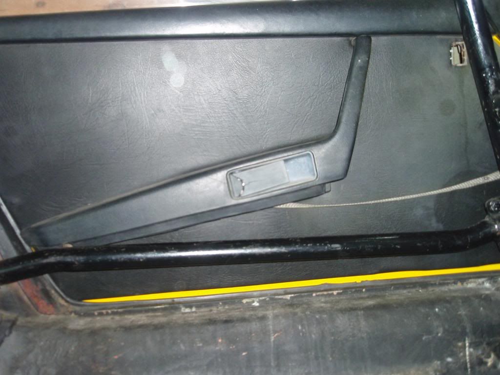
So compared to an unmolested (but crappy on the other side) one at the top
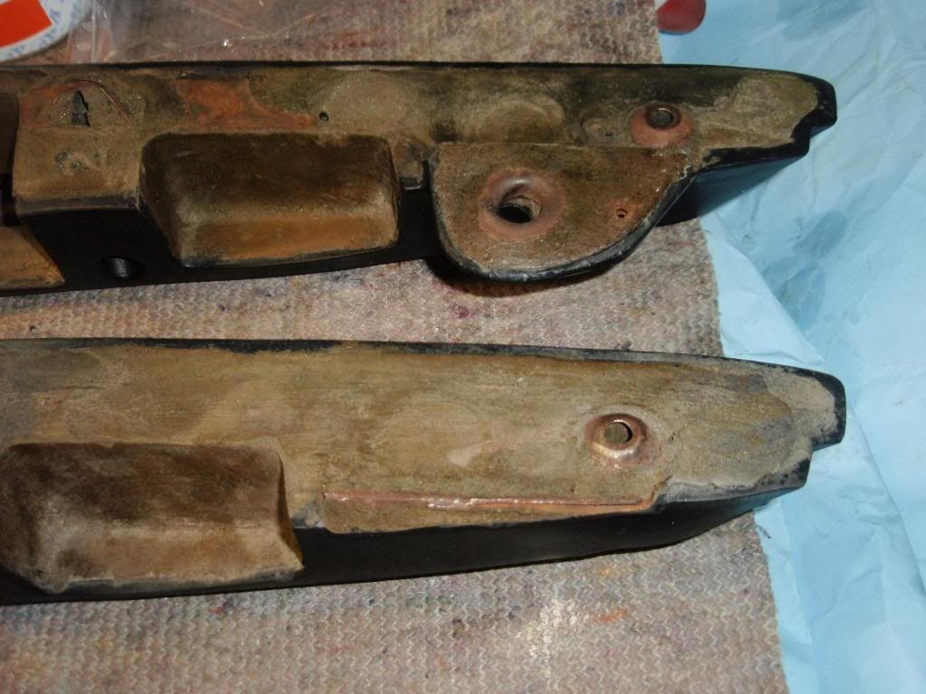
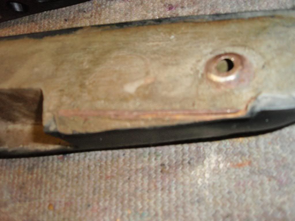
Bu**er - so off with the handle and as you can see at some point the bracket was just cut off
So out with the snips, a couple of sockets, a vice, a hammer and a punch. Tappety-tap, et voila
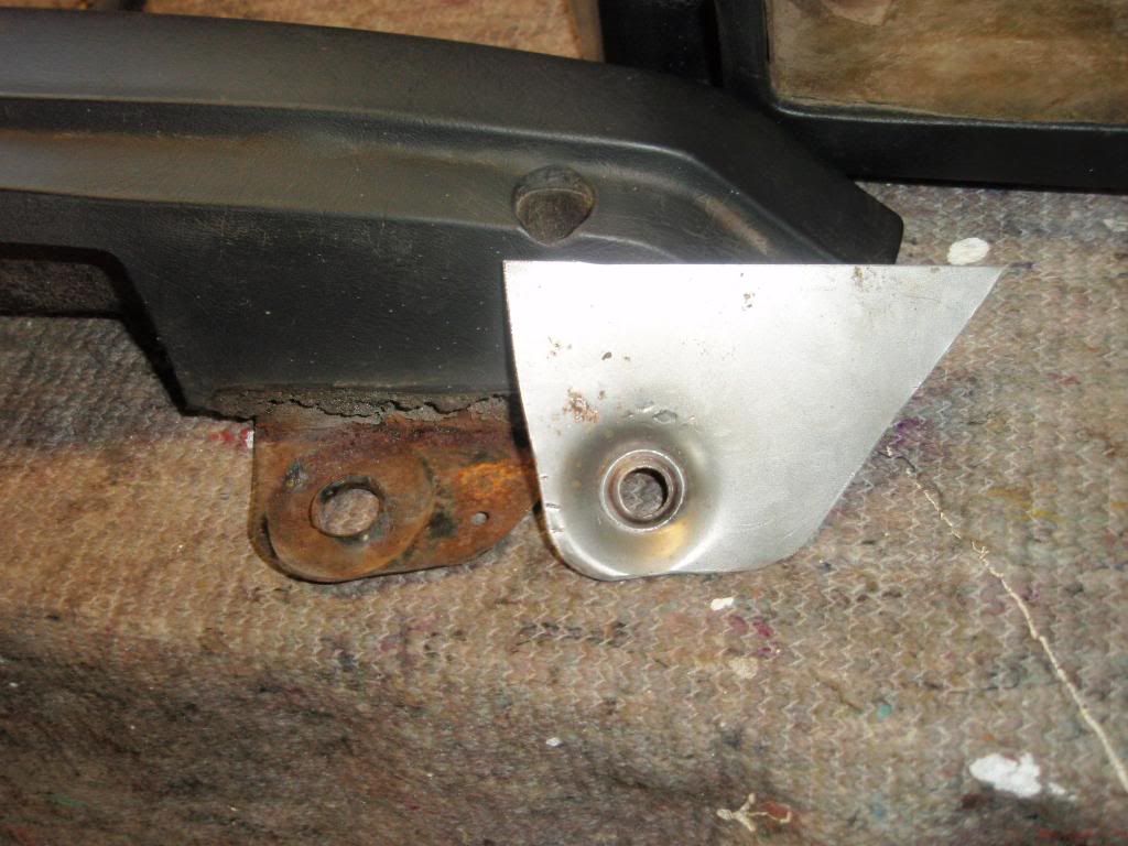
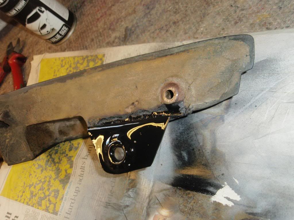
Offer up and weld
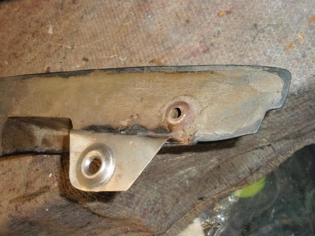
A coat of primer and paint ...... Now I cannot add the foam/vinyl thin covering that it would have had originally, but a) you cannot see it, and b) most of them seem to have lost that covering anyway!
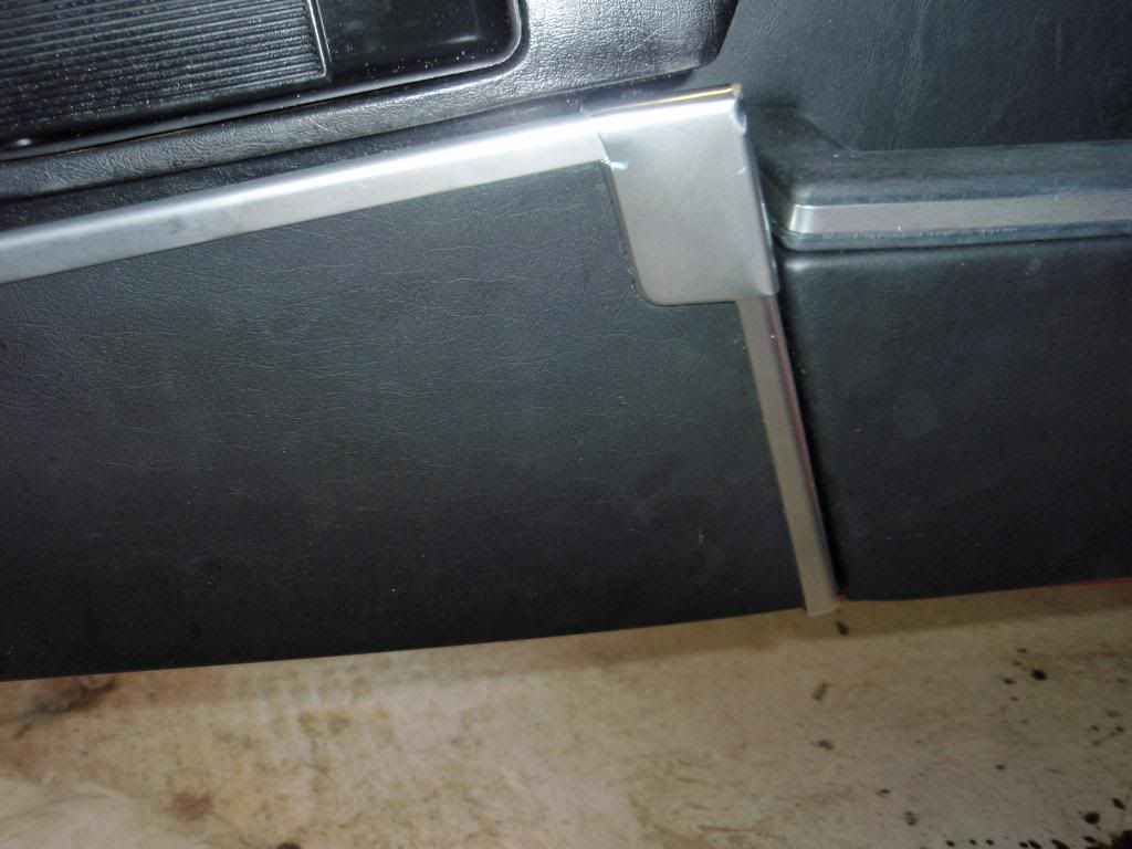
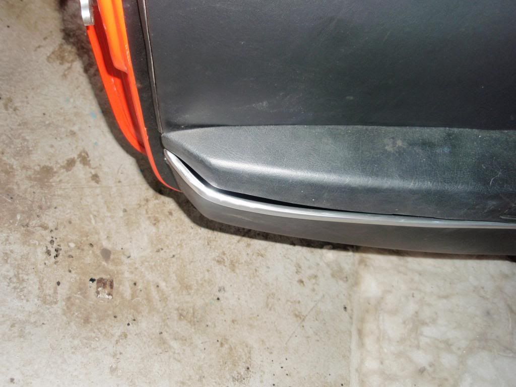
That'll do nicely ..... so back on with the handle and the front door pocket, and then offer up the rear. VFM .... would you f**king belieeeeeeve it! Even worse than the other side. Like Jimmy Hill's lower jaw.
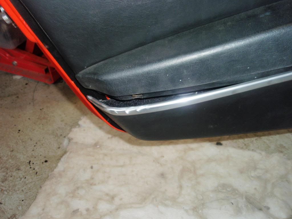
Better alignment at the front mind you
So out with the heat gun, bits of wood and some strapping
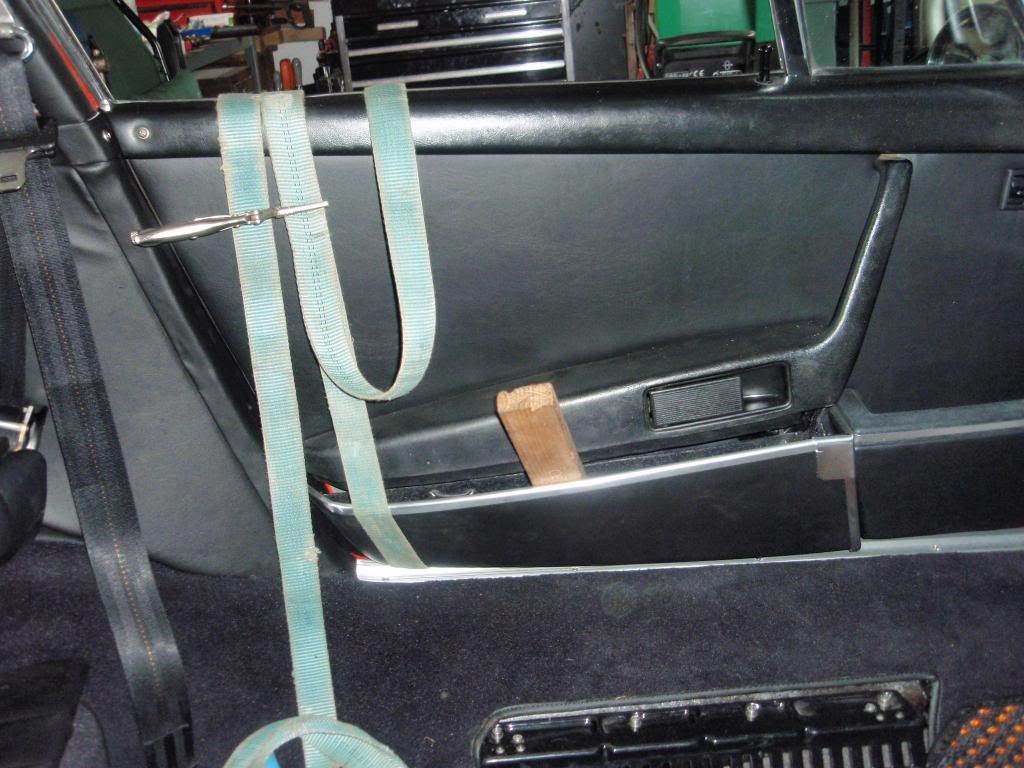
And some progress ...... needs another go to get it right but at least I can see it can be done. When you gently push the rear end of the pocket towards the door it lines up really well, moving both up as well as in - it is like the rear end of the pocket is twisted outwards compared with the front.
Having scoured the Revival car park (to the annoyance of a couple of owners ) I have yet to see a REALLY good alignment and fit, but I'm sure it can be done. Will persist...
Anyway on to Engine Games Part 2 - The Setback
Turned my attention to the passenger side door. All went together ok - new door card, the original door handle cleaned up really well. All it needed was a new handle - I guess it hardly got used. All assembled ready to fit the rear door pocket when it became obvious there was no rear hole for the bungee cord to go through. Seems at some point someone had 'offed' it so they could just fit the plain full cover door cards that were on the car when I got it. (see below)

So compared to an unmolested (but crappy on the other side) one at the top

Bu**er - so off with the handle and as you can see at some point the bracket was just cut off

So out with the snips, a couple of sockets, a vice, a hammer and a punch. Tappety-tap, et voila

Offer up and weld

A coat of primer and paint ...... Now I cannot add the foam/vinyl thin covering that it would have had originally, but a) you cannot see it, and b) most of them seem to have lost that covering anyway!

That'll do nicely ..... so back on with the handle and the front door pocket, and then offer up the rear. VFM .... would you f**king belieeeeeeve it! Even worse than the other side. Like Jimmy Hill's lower jaw.

Better alignment at the front mind you

So out with the heat gun, bits of wood and some strapping

And some progress ...... needs another go to get it right but at least I can see it can be done. When you gently push the rear end of the pocket towards the door it lines up really well, moving both up as well as in - it is like the rear end of the pocket is twisted outwards compared with the front.

Having scoured the Revival car park (to the annoyance of a couple of owners
Anyway on to Engine Games Part 2 - The Setback
Last edited by MT on Thu Sep 26, 2013 7:43 pm, edited 1 time in total.
'Creativity is the product of time wasted' Albert Einstein
1972 RHD 2.4E (ex Bob Watson racer - now in original Tangerine)
1966 LHD swb (Doctors car - now with Mrs. Ferrari in Madrid)
1966 TR4A (now sold and replaced by 1990 944 turbo)
1966 S2a Landrover
1972 RHD 2.4E (ex Bob Watson racer - now in original Tangerine)
1966 LHD swb (Doctors car - now with Mrs. Ferrari in Madrid)
1966 TR4A (now sold and replaced by 1990 944 turbo)
1966 S2a Landrover
Re: 2.4E From IKEA to Blut Orange
Engine Games Part 2 - The Setback
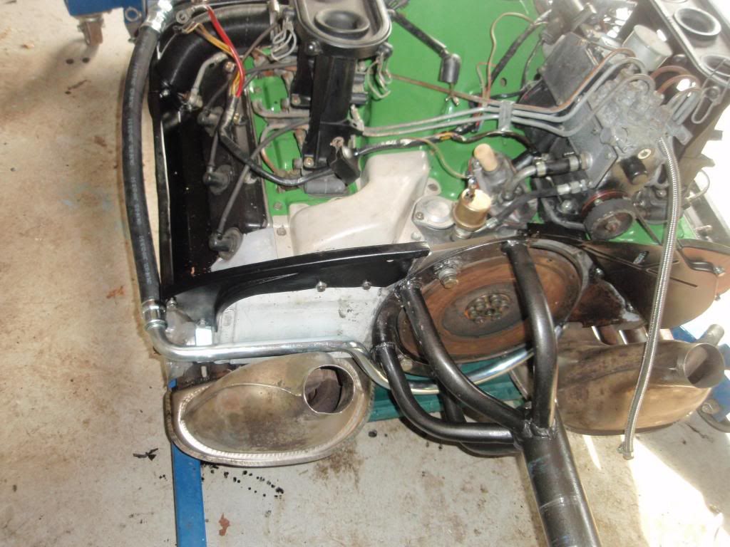
So I am preparing earlier last week for the arrival of my assistant on Friday to fit the engine and I get all the oil hoses out and ready. Fitted the two breather hoses under the rear RH wing to the oil tank, and the much trickier main hose from the oil filter housing to the top of the tank. There was a reason that my dismantling picture below shows the oil tank just removed with this hose still attached!
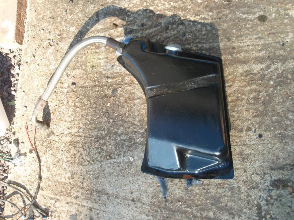
There is virtually no room under there to get any sort of wrench onto the gland nut. In the end an adjustable vice grip I bought years ago in France came up trumps, but for others I'd suggest fitting the two breather hoses and this main hose to the top of the oil tank BEFORE you put the tank in place. Only a minor issue this .... certainly not a setback...
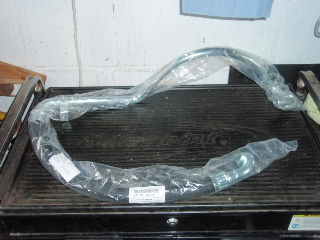
Anyway then on with the lower hose that connects via one very short and one 'S' hose to the engine oil cooler.
All cleaned up with new ss hose clips. Lovely. Setback here - no sir, let's keep moving on.
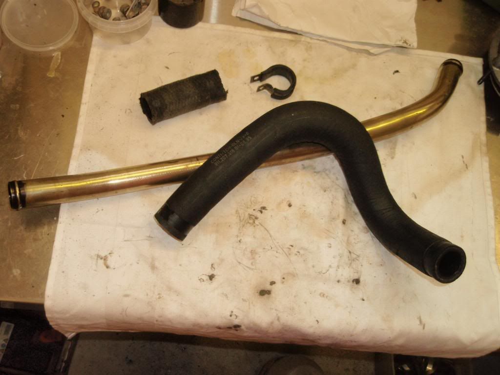
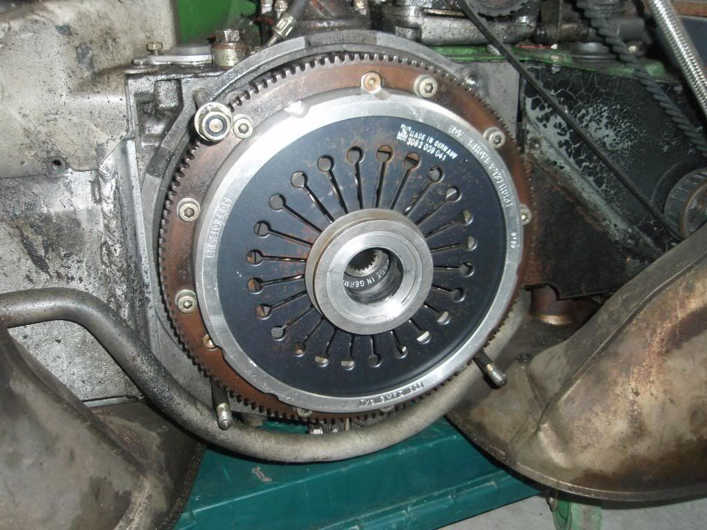
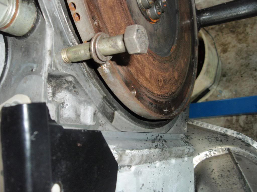
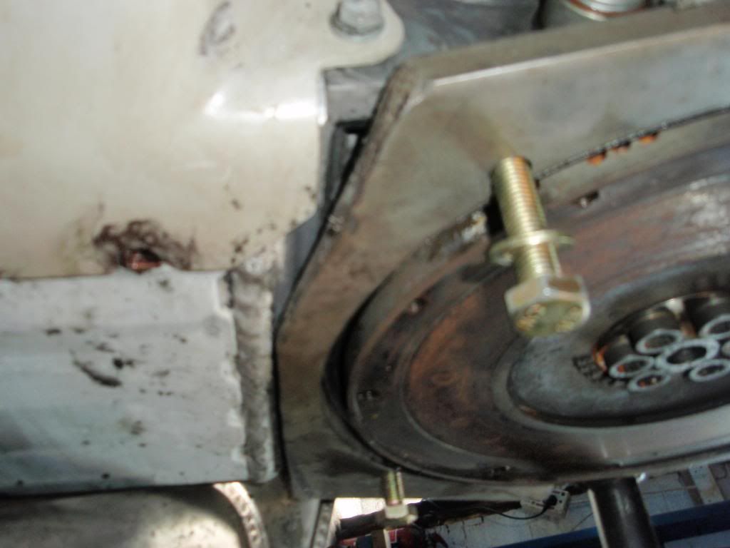
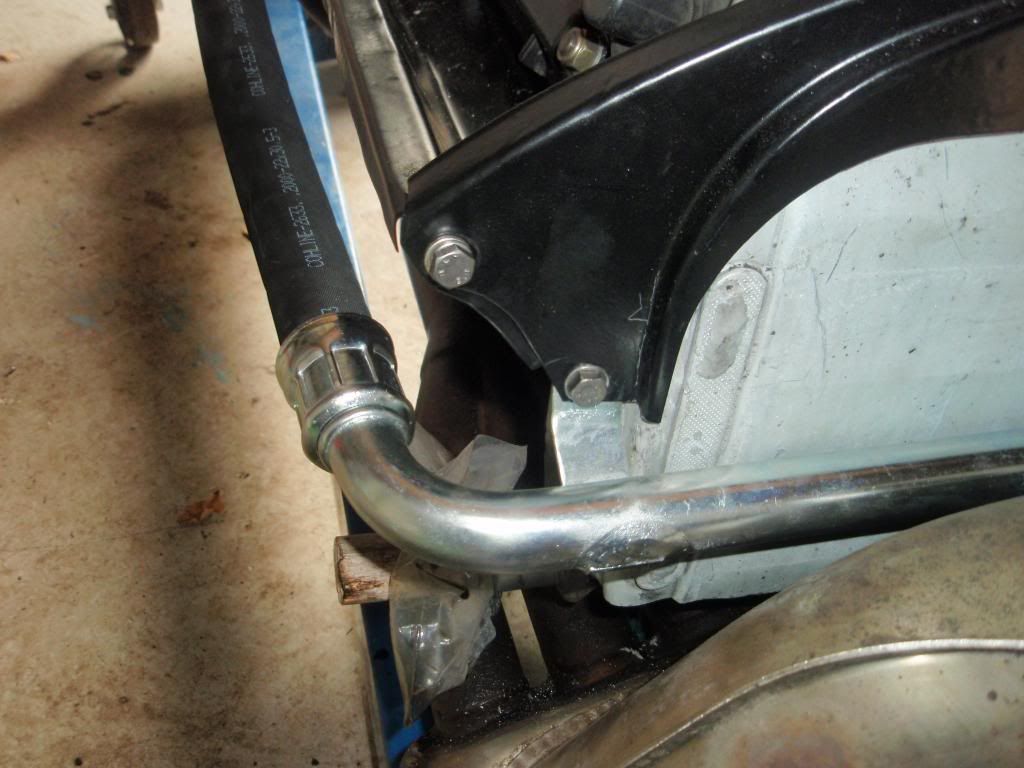
So then we come to the last main hose. The long one that is combined metal pipe and rubber pressure hose. It connects the LH front side of the engine case (oil pump) via the ?-shaped metal pipe under the gearbox and round and up via the rubber hose to the other connection on the oil filter. You can see part of the metal section in the photo below under the clutch plate
So now the setbacks come thick and fast..... try to keep up at the back
1. At some point the rubber hose section must have failed and to avoid some of the other setbacks below some PO/race mech decided to just use another piece of hose with double jubilee clips and a right angled pipe fitting to bridge the gap. I had forgotten about this until I looked back in my archive, and had forgotten to order another pipe. Order another, quick...
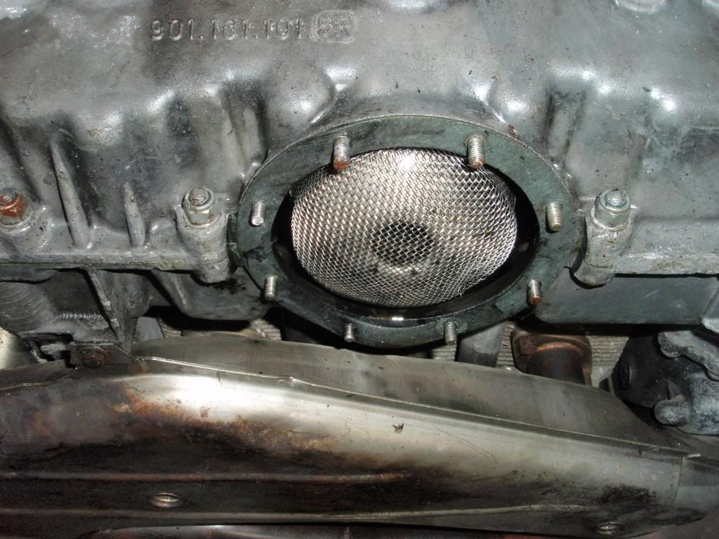
2. In order to get at the engine casing end of the pipe you need to remove the heat exchanger. In order to remove the heat exchanger you really want it on an engine stand. In order to get in on the stand you need to fit the mount bracket. In order to fit the bracket (see photo above) you need to remove the metal oil pipe. Catch 22. Bu**er. How's that work then....? (answers on a postcard please)
3. Sod that, we'll worry about that later. The pipe is u/s so I'll just hacksaw it off for now. Off with the clutch to get more space - best if I remove the studs as well. Top long stud is unusually tight, and eventually comes out with rather more 'case' attached to the threads than I'd like to see. Excessive use of thread-locker I think. Will be ok I think, but
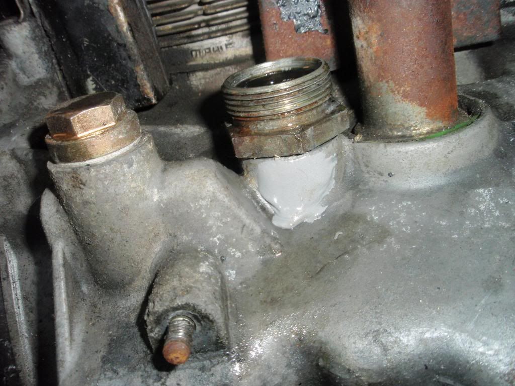
4. On the engine mount, on the stand, off with the heat exchanger...... to be greeted by...

... and what would that glob of yellow shite be then? Oh and over here, what's this grey snot..
.... why has this stud bolt got some silicon gloop all over it I wonder.
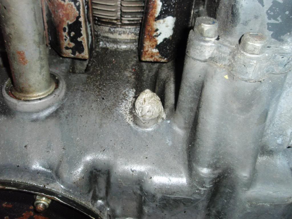
The yellow turd came straight off with a gentle pick to reveal
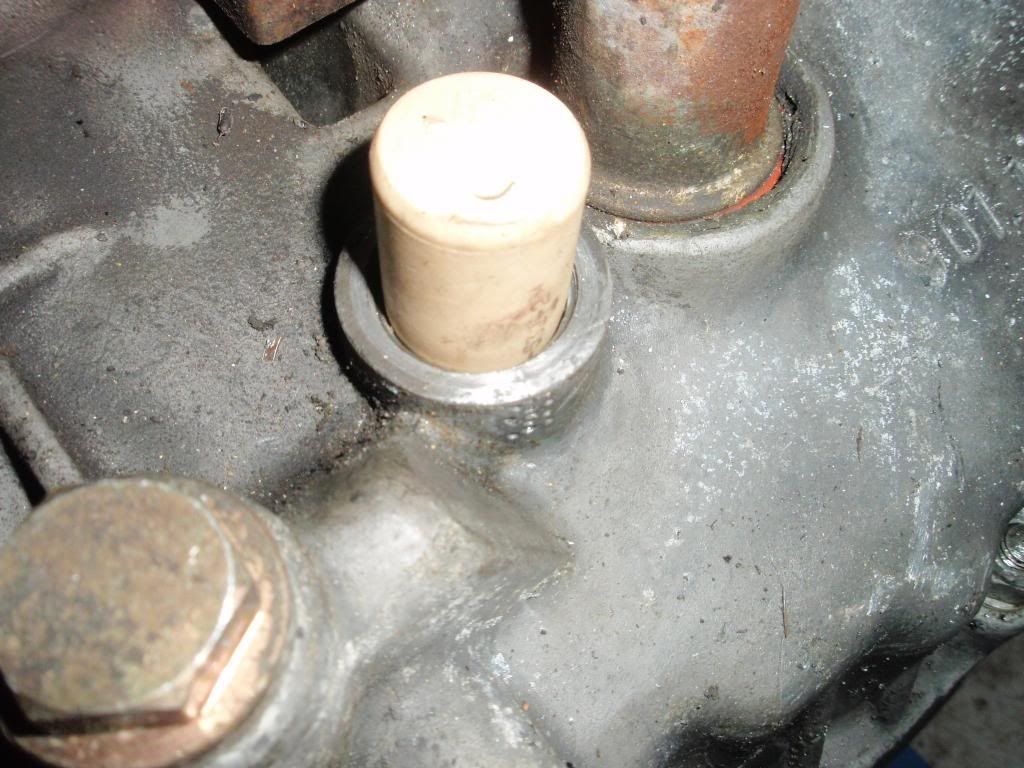
(excuse the cheap wine cork to stop detritus going deep)
You can (just) see the crack in the second crappy photo, and I suspect the punch holes are attempts to stop crack propagation before covering it with the yellow sealant, The silicone gloop was also probably just an attempt to stop an oil leak. Anyone know if there's an o ring on that stud?
Still thinking through what to do next, but I still think getting the engine running if possible to get a full worklist looks favourite. So (welcome thoughts here) plan currently is...
!. Use JB Weld to make a better job sealing the crack.
2. Ideally refit the hose and the heat exchanger on the stand if I can figure out how to do it. I am baffled why it is seemingly impossible to fit the oil pipe/hose with the engine mount in place. Is my existing hose the wrong one, has it been bent (not obvious), or what. I'm going to post a question in the main 911 section as I cannot be the first to hit this problem. Refitting the hose and the heat exchanger with the engine off the mount/stand is going to be fun (bordering on unsafe) I think.
3. Leave the case stud as it is to see how big a leak it is.
4. Put engine in and do the original testing I had planned, with all setbacks overcome!
So I am preparing earlier last week for the arrival of my assistant on Friday to fit the engine and I get all the oil hoses out and ready. Fitted the two breather hoses under the rear RH wing to the oil tank, and the much trickier main hose from the oil filter housing to the top of the tank. There was a reason that my dismantling picture below shows the oil tank just removed with this hose still attached!

There is virtually no room under there to get any sort of wrench onto the gland nut. In the end an adjustable vice grip I bought years ago in France came up trumps, but for others I'd suggest fitting the two breather hoses and this main hose to the top of the oil tank BEFORE you put the tank in place. Only a minor issue this .... certainly not a setback...
Anyway then on with the lower hose that connects via one very short and one 'S' hose to the engine oil cooler.

All cleaned up with new ss hose clips. Lovely. Setback here - no sir, let's keep moving on.
So then we come to the last main hose. The long one that is combined metal pipe and rubber pressure hose. It connects the LH front side of the engine case (oil pump) via the ?-shaped metal pipe under the gearbox and round and up via the rubber hose to the other connection on the oil filter. You can see part of the metal section in the photo below under the clutch plate

So now the setbacks come thick and fast..... try to keep up at the back
1. At some point the rubber hose section must have failed and to avoid some of the other setbacks below some PO/race mech decided to just use another piece of hose with double jubilee clips and a right angled pipe fitting to bridge the gap. I had forgotten about this until I looked back in my archive, and had forgotten to order another pipe. Order another, quick...
2. In order to get at the engine casing end of the pipe you need to remove the heat exchanger. In order to remove the heat exchanger you really want it on an engine stand. In order to get in on the stand you need to fit the mount bracket. In order to fit the bracket (see photo above) you need to remove the metal oil pipe. Catch 22. Bu**er. How's that work then....? (answers on a postcard please)
3. Sod that, we'll worry about that later. The pipe is u/s so I'll just hacksaw it off for now. Off with the clutch to get more space - best if I remove the studs as well. Top long stud is unusually tight, and eventually comes out with rather more 'case' attached to the threads than I'd like to see. Excessive use of thread-locker I think. Will be ok I think, but
4. On the engine mount, on the stand, off with the heat exchanger...... to be greeted by...

... and what would that glob of yellow shite be then? Oh and over here, what's this grey snot..

.... why has this stud bolt got some silicon gloop all over it I wonder.
The yellow turd came straight off with a gentle pick to reveal


(excuse the cheap wine cork to stop detritus going deep)
You can (just) see the crack in the second crappy photo, and I suspect the punch holes are attempts to stop crack propagation before covering it with the yellow sealant, The silicone gloop was also probably just an attempt to stop an oil leak. Anyone know if there's an o ring on that stud?
Still thinking through what to do next, but I still think getting the engine running if possible to get a full worklist looks favourite. So (welcome thoughts here) plan currently is...
!. Use JB Weld to make a better job sealing the crack.
2. Ideally refit the hose and the heat exchanger on the stand if I can figure out how to do it. I am baffled why it is seemingly impossible to fit the oil pipe/hose with the engine mount in place. Is my existing hose the wrong one, has it been bent (not obvious), or what. I'm going to post a question in the main 911 section as I cannot be the first to hit this problem. Refitting the hose and the heat exchanger with the engine off the mount/stand is going to be fun (bordering on unsafe) I think.
3. Leave the case stud as it is to see how big a leak it is.
4. Put engine in and do the original testing I had planned, with all setbacks overcome!
'Creativity is the product of time wasted' Albert Einstein
1972 RHD 2.4E (ex Bob Watson racer - now in original Tangerine)
1966 LHD swb (Doctors car - now with Mrs. Ferrari in Madrid)
1966 TR4A (now sold and replaced by 1990 944 turbo)
1966 S2a Landrover
1972 RHD 2.4E (ex Bob Watson racer - now in original Tangerine)
1966 LHD swb (Doctors car - now with Mrs. Ferrari in Madrid)
1966 TR4A (now sold and replaced by 1990 944 turbo)
1966 S2a Landrover
-
grannysmith
- DDK forever
- Posts: 586
- Joined: Fri Sep 19, 2008 5:58 pm
- Location: Sheffield
Re: 2.4E From IKEA to Blut Orange
Hi Mick
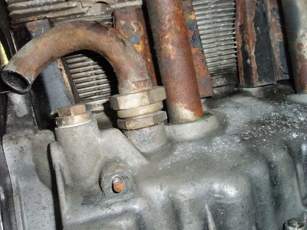
I've had similar problems with that oil line. My old one fitted properly and the yoke went on while it was in place.

But the hose was perished so I bought a new one from the dealer. The fit was shocking (door pocket bad) and it had to be tweaked quite a bit before I could fit it to the engine. The joint to the engine was misligned as well. If your motor had one fitted that was as badly shaped as this one it might have caused the crack too. A long shot, but maybe.


It did go on in the end with enough room for the yoke.

Mick
'72 Targa 2.4T/E in Chartreuse
My Google search bar knows two words and they both begin POR..
'72 Targa 2.4T/E in Chartreuse
My Google search bar knows two words and they both begin POR..
Re: 2.4E From IKEA to Blut Orange
Engine Games - Part 3 The comeback trail
First of all, thanks Mick (grannysmith) for you post above,
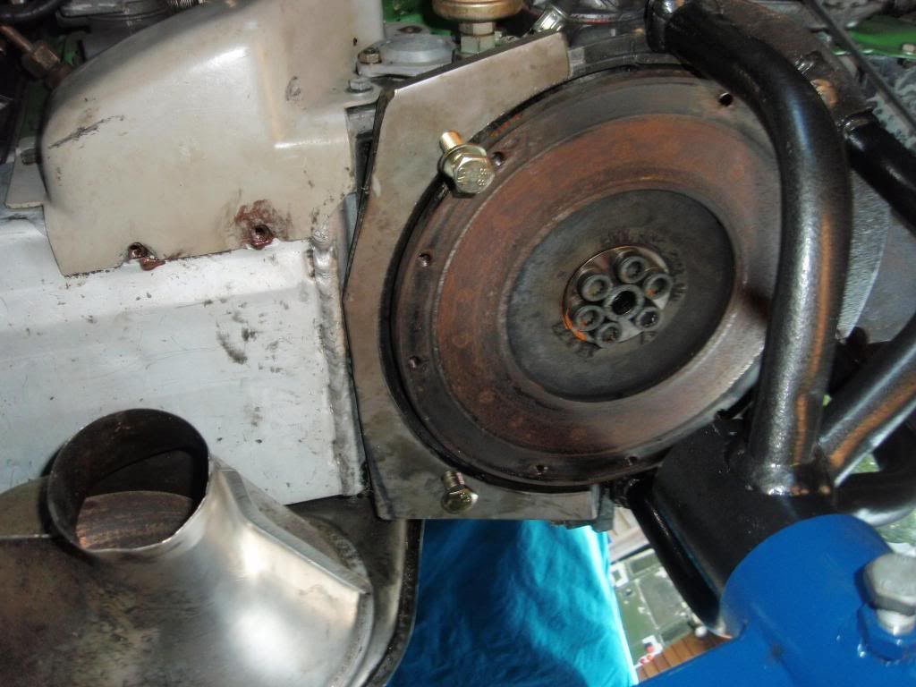
Your photos not only assured me it could be done, but also solved another dilemma. As you can see in my photos I eventually got the engine mount fitted, but to the LH case half. This is because the on the RH side the oil cooler projects further out than the face the mount attaches to - see below
As it clearly does on yours as well
But then I saw that your engine mount has a chamfered back edge, unlike my 'beetlejac' version. So a little engineering would clearly be required as when the new pipe arrived
It was obvious that the mount would need to be on the RH case half as it is in your photos. It does seem the shape of the metal section of the pipe is different to the version that was on the engine originally and that it should fit while on the stand. (hopefully better than yours did to begin with!)
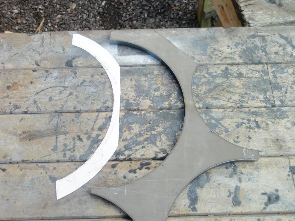
So off I went to a local fabricator. Could he cut me a piece of 12mm steel plate to shape .... Well yes, but he'd need an engineering diagram, £40 and a week. Bu**er ...... but then as I was walking past the scrap bin on my way out (I ALWAYS walk past the scrap bin in these places!). I spotted the offcuts from some earlier work. VM ... would you belieeeeeve it! The paper shape is roughly what I needed, and the radius of the off cut edge is virtually identical. Result!
After a bit of disc cutting and grinding. Voila!
I'll swap the mount over tomorrow...... although I am really not happy about the state of the threads in the upper stud hole on that side. The removal of the stud has really taken out a lot of case and although I've re-tapped the hole the stud is really quite loose and floppy over much of it's travel ....... so I think a helicoil is called for. Also I needed some new studs as the lower ones are slightly bent as well. Couldn't get any locally so I just bought longer M10 bolts, cut to correct length and re-threaded the end. You can see what my posh 'stud-extractor' did to the threads on the original on the far left below.

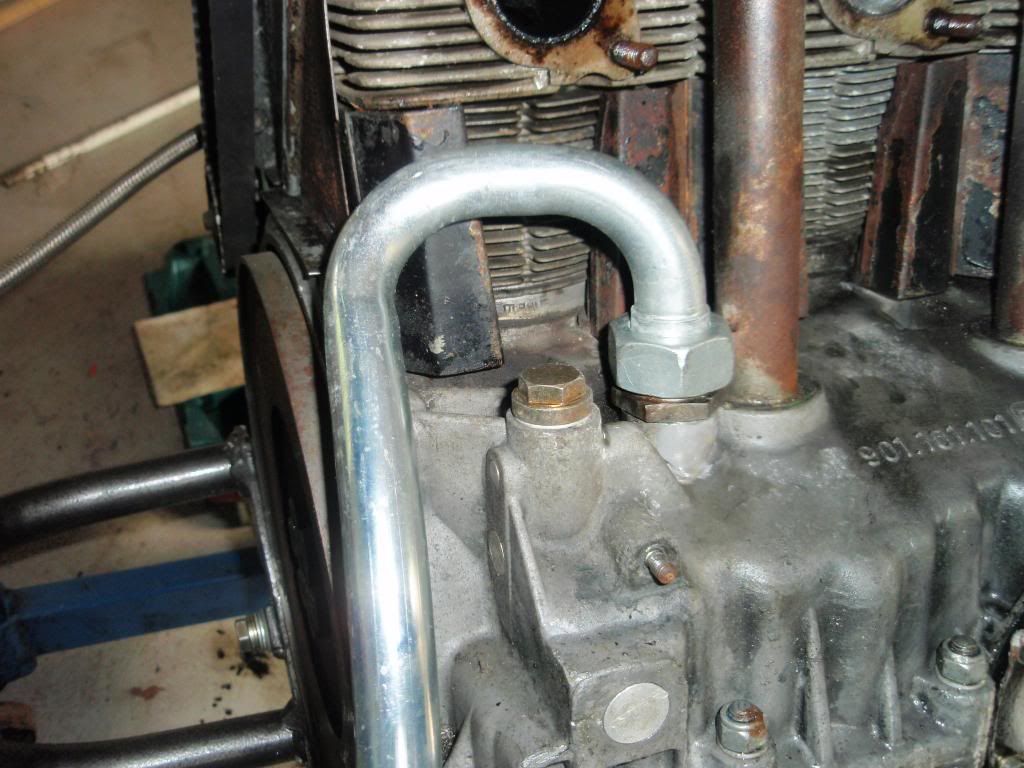
Then in with the coupling in the cracked oil passageway, tighten, and add JB Weld. Hopefully this will be enough to stop any leak until I get the engine tested. Any views on the necessity to re-weld the case when I eventually strip the engine?
First of all, thanks Mick (grannysmith) for you post above,
Your photos not only assured me it could be done, but also solved another dilemma. As you can see in my photos I eventually got the engine mount fitted, but to the LH case half. This is because the on the RH side the oil cooler projects further out than the face the mount attaches to - see below

As it clearly does on yours as well
But then I saw that your engine mount has a chamfered back edge, unlike my 'beetlejac' version. So a little engineering would clearly be required as when the new pipe arrived

It was obvious that the mount would need to be on the RH case half as it is in your photos. It does seem the shape of the metal section of the pipe is different to the version that was on the engine originally and that it should fit while on the stand. (hopefully better than yours did to begin with!)
So off I went to a local fabricator. Could he cut me a piece of 12mm steel plate to shape .... Well yes, but he'd need an engineering diagram, £40 and a week. Bu**er ...... but then as I was walking past the scrap bin on my way out (I ALWAYS walk past the scrap bin in these places!). I spotted the offcuts from some earlier work. VM ... would you belieeeeeve it! The paper shape is roughly what I needed, and the radius of the off cut edge is virtually identical. Result!

After a bit of disc cutting and grinding. Voila!


I'll swap the mount over tomorrow...... although I am really not happy about the state of the threads in the upper stud hole on that side. The removal of the stud has really taken out a lot of case and although I've re-tapped the hole the stud is really quite loose and floppy over much of it's travel ....... so I think a helicoil is called for. Also I needed some new studs as the lower ones are slightly bent as well. Couldn't get any locally so I just bought longer M10 bolts, cut to correct length and re-threaded the end. You can see what my posh 'stud-extractor' did to the threads on the original on the far left below.

Then in with the coupling in the cracked oil passageway, tighten, and add JB Weld. Hopefully this will be enough to stop any leak until I get the engine tested. Any views on the necessity to re-weld the case when I eventually strip the engine?

'Creativity is the product of time wasted' Albert Einstein
1972 RHD 2.4E (ex Bob Watson racer - now in original Tangerine)
1966 LHD swb (Doctors car - now with Mrs. Ferrari in Madrid)
1966 TR4A (now sold and replaced by 1990 944 turbo)
1966 S2a Landrover
1972 RHD 2.4E (ex Bob Watson racer - now in original Tangerine)
1966 LHD swb (Doctors car - now with Mrs. Ferrari in Madrid)
1966 TR4A (now sold and replaced by 1990 944 turbo)
1966 S2a Landrover
Re: 2.4E From IKEA to Blut Orange
Engine Games Part-3.5 Comeback continues....
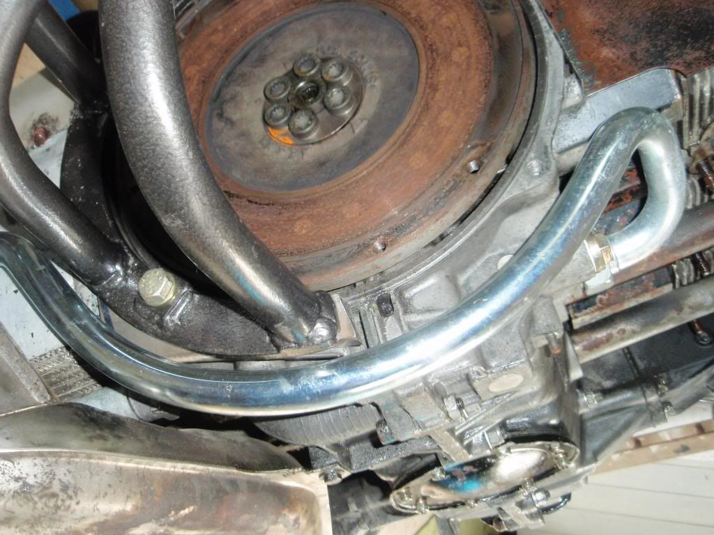
So swap over the engine mount and try the new 'spacer'. Works a treat. Test fit the pipe - lines up really well and such that it's obvious that you can install/remove the mount. So it is clear the existing one was a bodge of some kind. And the union to the engine case was also a straight and true fit, so none of Mick's (granny smith) tweeking required.
Only other bit to note is that while I had the sump plate off it seems that there is a later, Carrera oil pump fitted ..... and presumably the oil bypass mod done as well. So a bit of good news there as well.
Just need some pipe to replace the dried out cold start hosing to the stacks, and a helicoil kit for the top LH stud before I try to install and start.
So swap over the engine mount and try the new 'spacer'. Works a treat. Test fit the pipe - lines up really well and such that it's obvious that you can install/remove the mount. So it is clear the existing one was a bodge of some kind. And the union to the engine case was also a straight and true fit, so none of Mick's (granny smith) tweeking required.


Only other bit to note is that while I had the sump plate off it seems that there is a later, Carrera oil pump fitted ..... and presumably the oil bypass mod done as well. So a bit of good news there as well.
Just need some pipe to replace the dried out cold start hosing to the stacks, and a helicoil kit for the top LH stud before I try to install and start.

'Creativity is the product of time wasted' Albert Einstein
1972 RHD 2.4E (ex Bob Watson racer - now in original Tangerine)
1966 LHD swb (Doctors car - now with Mrs. Ferrari in Madrid)
1966 TR4A (now sold and replaced by 1990 944 turbo)
1966 S2a Landrover
1972 RHD 2.4E (ex Bob Watson racer - now in original Tangerine)
1966 LHD swb (Doctors car - now with Mrs. Ferrari in Madrid)
1966 TR4A (now sold and replaced by 1990 944 turbo)
1966 S2a Landrover
Re: 2.4E From IKEA to Blut Orange
Sorry John,johnM wrote:Nice to see you last month, sorry we couldn't stay any longer.
Kind regards.
Meant to respond earlier that if you have cause to pass by again please do call in. A longer chat and a cup (or glass!) of something would be pleasant.
Mick
'Creativity is the product of time wasted' Albert Einstein
1972 RHD 2.4E (ex Bob Watson racer - now in original Tangerine)
1966 LHD swb (Doctors car - now with Mrs. Ferrari in Madrid)
1966 TR4A (now sold and replaced by 1990 944 turbo)
1966 S2a Landrover
1972 RHD 2.4E (ex Bob Watson racer - now in original Tangerine)
1966 LHD swb (Doctors car - now with Mrs. Ferrari in Madrid)
1966 TR4A (now sold and replaced by 1990 944 turbo)
1966 S2a Landrover