
http://forums.pelicanparts.com/porsche- ... chart.html
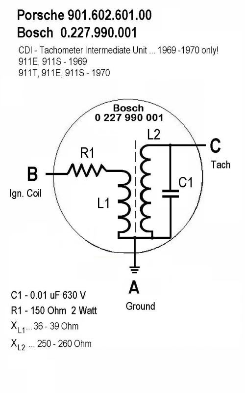
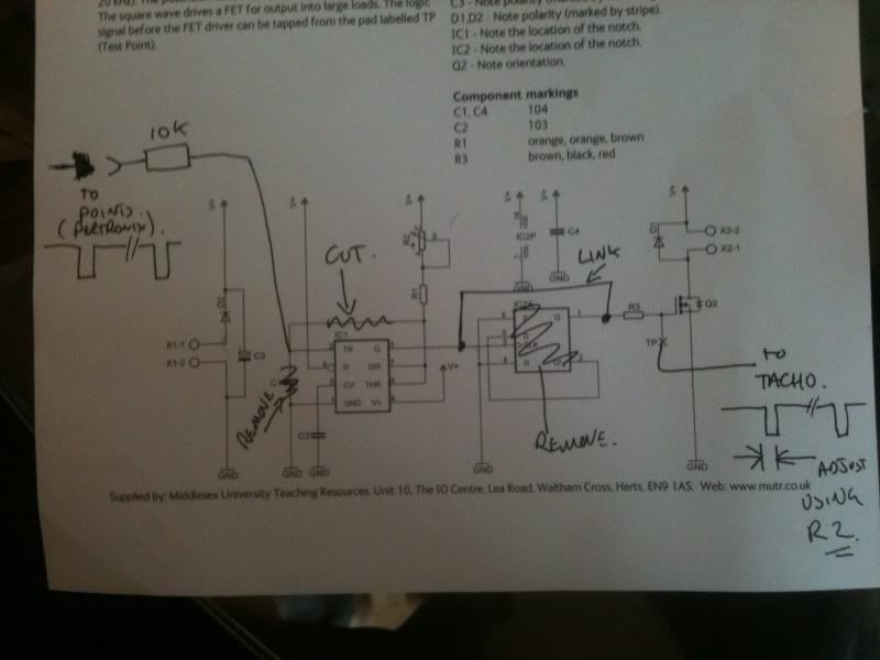
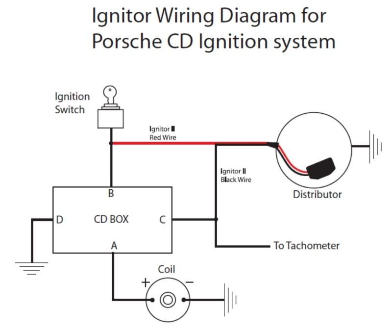
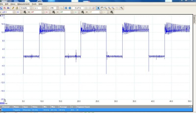
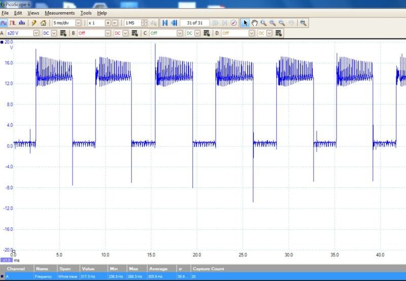
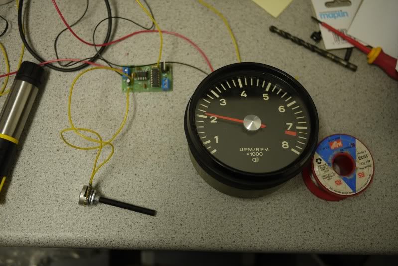
My unit is has a pin labelled /1 and is driven from a Ballast Unit (bosch) which appears to be an RLC circuit. I wanted to establish if it was my tacho or feed, my tacho works from a 12v square wave input, so I decided to build a square wave generator, lucky for me maplins sell a kit (Order Code: N41FL) for £6.99
The first picture is the ccrt board and tacho at 2000rpm
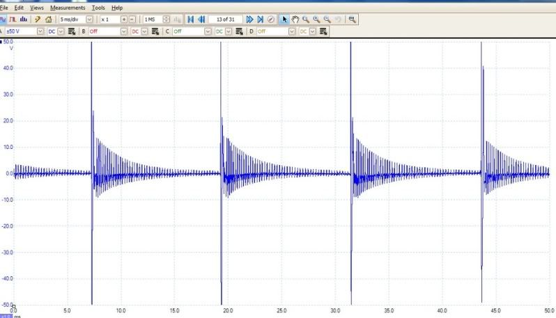
This picture shows the square wave output from the unit.
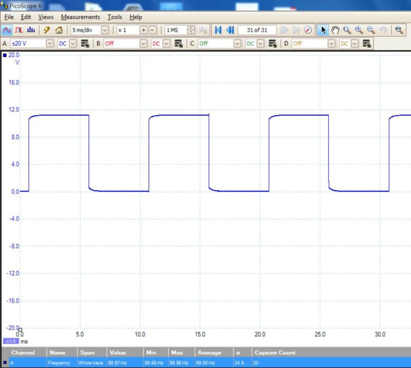
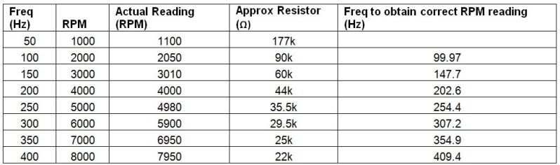
The table below shows the approx resistor values you need to produce the various square wave freq’s. As you can see my tacho varies slightly, at an applied freq of 100Hz this should produce 2000rpm, but it shows 2050, to obtain 2000rpm on the tacho I need to apply 99.97Hz
I hope this will be useful to someone who has similar issues as mine, most of my info came from pelicanparts forum, so have a look.
http://forums.pelicanparts.com/porsche- ... -74-a.html
I still have a problem with my tacho drive signal, so if anyone has any ideas let me know (or has a spare ballast unit i could try).
Cheers
Nick